Article

Micro-Brazing of Stainless Steel Using Ni-P Alloy Plating

1
Graduate School of Science and Technology, Gunma University, 1-5-1, Tenjin-cho, Kiryu 376-8515, Japan
2
Faculty of Science and Technology, Gunma University, 1-5-1 Tenjin-cho, Kiryu 376-8515, Japan
3
Waki Factory Inc., 6-760 Higashi-sayamagaoka, Tokorozawa 359-1106, Japan
4
Faculty of Engineering, Shinshu University, 4-17-1 Wakasato, Nagano 380-8553, Japan
*
Author to whom correspondence should be addressed.
Appl. Sci. 2019, 9(6), 1094; https://doi.org/10.3390/app9061094
Submission received: 27 December 2018 / Revised: 21 February 2019 / Accepted: 11 March 2019 / Published: 15 March 2019
(This article belongs to the Section Nanotechnology and Applied Nanosciences)

Abstract

:
A Ni-P plated layer of 20 μm thickness containing 11 wt.% P was formed on the surface of a stainless steel (SUS304) plate by electroplating. The microstructure and joint strength of the brazed joint with the electroplated Ni-11P layer were investigated. The results indicated that the filler metal was homogeneously distributed between the SUS304 plates and no voids or flaws formed in the brazed filler zone. Fe-Ni-Cr solid solutions were formed at the brazed interface. Moreover, P was mainly concentrated in such brazed filler zone to form P-containing phases. The average shear strength of the brazed joints was determined to be 47.3 MPa. The results demonstrated that the brazing of SUS304 plates using the electroplated Ni-11P layer as the filler metal was successfully realized.

1. Introduction

Stainless steel has often been used as a material for heat exchangers because of its excellent corrosion resistance and heat resistance. Nickel-based filler alloys are commonly used for brazing stainless steel, owing to their good corrosion resistance and oxidation resistance. To lower the melting point of the nickel-based filler metal, it generally contains a large amount of a melting point depressant, such as P, B, or Si. However, nickel-based alloys containing a melting point depressant easily form a eutectic structure that causes the brazed joint to be brittle [1,2]. When brazing the components with a small thickness, owing to the rapid diffusion of boron into the substrate and its low solubility in austenite, large amounts of brittle borides precipitate in the bonding-affected zone, increasing the brittleness of the bonding. Furthermore, the borides can decrease the corrosion resistance of the brazed joint, shortening the life span of the components. Compared with boron, it is difficult for phosphorus to diffuse into the substrate and generate metal compounds in the bonding-affected zone owing to its low diffusion and large atomic radius. In addition, it was found that nickel-based alloys containing phosphorus exhibit very good wettability and may form a ductile solid solution in a joint in the case of a very narrow gap [3]. Therefore, the Ni-P filler alloy is more suitable for the brazing of stainless steel with a small thickness.
For a Ni-P alloy, some melting will occur at the lowest melting point (875 °C) of the Ni-P system, regardless of the phosphorus content, provided it is greater than 0.2%. Therefore, it is easy to set the brazing temperature using a eutectic Ni-P alloy in industrial applications. Currently, a eutectic Ni-(10-12)P (wt.%) alloy, code name BNi-6 (JIS Z 3265), is commercially used as the filler metal owing to its lowest melting temperature in the Ni-P system, extremely good fluidity and excellent brazability [4]. However, with the reduction in the weight of heat exchangers, especially multilayer plate fin heat exchangers, the stainless steel components of heat exchangers have become thinner and smaller. Therefore, a filler metal with a thickness of around 20 μm is required to join the stainless steel. Usually, BNi-6 filler metal is formed as a foil or paste because of its inherent hardness and brittleness, making it difficult to supply the correct quantity of the filler metal to the brazed area. An inappropriate quantity of the filler metal causes degradation and decreases the reliability of the brazed joint. In addition, the thickness of the filler metal is usually below 0.1 mm, and it is difficult to form a foil or paste with such a thickness [5].
It is widely known that Ni-P alloy layers can be produced by rapid quenching, ion implantation, vapor deposition, and chemical deposition [6,7,8]. However, for various reasons, these techniques do not lend themselves to industrial-scale applications. The chemical deposition method is more economically favorable than these techniques, and alloy layers of uniform thickness can be obtained by controlling the plating conditions. However, the plating solutions used in chemical deposition are laborious to control and produce large amounts of waste owing to their short life span. Furthermore, it is difficult to accurately control the phosphorus content of the plated layers because the properties of the plating solution change with time. Compared with the case of electrodeposition, the deposition rate of chemical deposition is low and a high operating temperature (about 80–90 °C) is required [8]. On the other hand, electrodeposition has been found useful at the industrial scale in preparing thin alloy layers, owing to its higher deposition rate and lower operating temperature than chemical deposition. Furthermore, variations in solution composition and operating parameters have resulted in a number of stable solutions capable of producing high-quality Ni-P plating layers [9,10,11,12,13].
Therefore, in this study, electroplating was used to form a thin Ni-11P (wt.%) alloy layer on the surface of a stainless steel plate as the filler metal. The brazing of the stainless steel plates was conducted using the electroplated Ni-11P alloy layer. Moreover, the microstructure was observed and the joint strength of the brazed joint was investigated.

2. Experimental Procedure

A plating bath (Figure 1) with a volume of 5 L was employed for the electrodeposition of the Ni-P alloy with a phosphorus acid-nickel salt system solution. The bath composition and concentration used for the Ni-P alloy electrodeposition are listed in Table 1. The solution was prepared using analytic-grade chemicals and pure water. The plating conditions used in this study were a bath temperature of 50 °C, a current density (C.D.) of 1.0–4.0 A/dm2, a plating time of 40–180 min and an air pump used for stirring. In this study, no pH adjustments were made during the electrodeposition of the Ni-P alloy. A pure nickel plate was used as the anode. A stainless steel plate, which had an exposed surface area of 10 cm2 (3 × 3.3 cm2, shown in Figure 1), was used as the cathode. Before plating, the stainless steel plate was mechanically polished with a #1000 emery paper, degreased with acetone, rinsed with tap water and dried with a dryer.
The chemical composition analysis of the Ni-11P plated layer was performed by X-ray fluorescence (XRF, Shimadzu XRF-1700, Shimadzu, Kyoto, Japan) at a voltage of 40 kV and a current of 95 mA at a scan rate of 8°/min with an aperture of 20 mm. The structure of the Ni-11P plated layer was investigated by X-ray diffraction (XRD, Rigaku RINT 2200 VF, Rigaku, Tokyo, Japan) analysis at 40 kV and 20 mA with Cu Kα radiation at a scan rate of 0.02°/s in the 2θ range of 30–70°. The thickness of the plated layer was measured with a micrometer. The surface morphology of the plated layer was investigated by a scanning electron microscopy (FE-SEM, HITACHI S-4300SE/N, HITACHI, Tokyo, Japan) at an acceleration voltage of 10 kV and a probe current of approximately 10 μA.
The brazing of the stainless steel plate with the electroplated Ni-11P alloy layer was conducted using a hydrogen reduction furnace with a dew point of −50 °C. The brazing temperature and the holding time at the brazing temperature were set to 1020 °C and 10 min, respectively. Figure 2 shows the geometry and dimensions of the brazed joint specimen. Specimens for cross-sectional investigation were cut with a cutter, embedded in epoxy resin, and polished with a 1 μm Al2O3 suspension. The microstructure of the brazed joint was analyzed by an electron probe X-ray microanalyzer (EPMA, Shimadzu EPMA-1600, Shimadzu, Kyoto, Japan) at an acceleration voltage of 15 kV, a sample current of 34 nA for backscattered electrons (BSE) image observation and a current of 50–100 nA for mapping analysis.
Shear tests were performed at room temperature with an Instron5567 universal testing machine (Instron, Grove, PA, USA) to evaluate the shear strength of the brazed joints. The cross-head speed for the shear tests was set to 10 mm/min. After the shear test, the fracture mode observation of the brazed joint was performed by the SEM and an optical microscopy (OM, VK-X150, KEYENCE, Osaka, Japan).

3. Results and Discussion

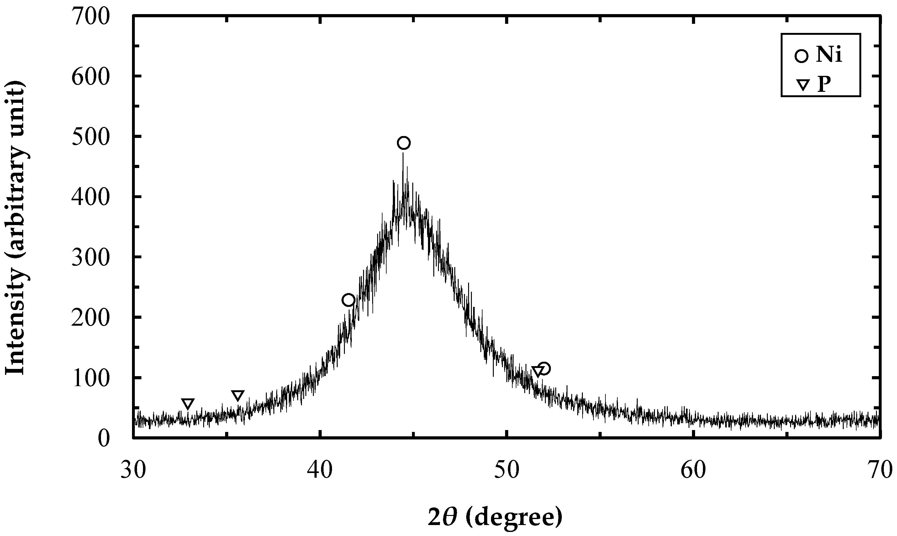
3.1. Formation of Ni-11P Alloy Plated Layer

Figure 3 shows the effects of the H3PO3 concentration on the P content and thickness of the Ni-P plated layers. With increasing H3PO3 concentration in the bath, the P content in the plated layer increases, whereas the thickness of the plated layer decreases. The mechanism of the Ni-P electrodeposition process involves the following reactions [14,15]:
Ni 2 + + 2 e Ni ,
2 H + + 2 e H 2 ,
H 3 PO 3 + 6 H + + 6 e PH 3 + 3 H 2 O ,
2 PH 3 + 3 Ni 2 + 3 Ni + 2 P + 6 H + ,
where reactions (1)–(3) are electrochemical reactions and reaction (4) is a chemical reaction. Increasing the H3PO3 concentration in the bath clearly accelerates the reactions (3) and (4), which increases the P content in the plated layers. In addition, increasing the H3PO3 concentration in the bath solution reduces the pH, thus accelerating the reaction (2). Consequently, the reaction (1) was significantly inhibited, decreasing the thickness of the plated layer.
The chemical composition data obtained by XRF analysis are plotted in Figure 3. The results show that a Ni-P plated layer of 20 μm thickness containing 11 wt.% P can be obtained when the H3PO3 concentration in the bath is approximately 0.4 M under the plating conditions of a current density of 2.0 A/dm2 and a plating time of 90 min.
The XRD analysis result for the Ni-11P plated layer is presented in Figure 4. The broad peak in the XRD spectra of the plated layer at 2θ of 44.44° suggests that the electroplated Ni-11P alloy layer has an amorphous structure. The incorporation of phosphorus in the nickel generally increases the number of defects in the crystalline lattice of the Ni-P plating layer, thereby transforming the plating layer from crystalline to amorphous [16]. No peaks from Ni3P or other Ni-P compounds were detected in the electroplated Ni-11P layer.

3.2. Effect of Current Density on Surface Morphology of Ni-P Alloy Plated Layer

Figure 5 shows the SEM micrographs of the surface morphology of the Ni-P plated layers under different current densities. When the current density was increased from 1 A/dm2 to 2 A/dm2, the size of the spherical nodules on the surface of the plated layer decreased. Next, the nodules became elongated when the current density was increased to 4 A/dm2. In addition, with the increase in the current density, the plated layer exhibited a higher porosity (shown in Figure 5c). The porous microstructure was ascribed to the enhanced hydrogen evolution reaction, in consequence, a series of hydrogen evolution channels formed in the plated layer. The higher current density resulted in a loose plated layer. Therefore, the optimal current density is considered to be 2.0 A/dm2.

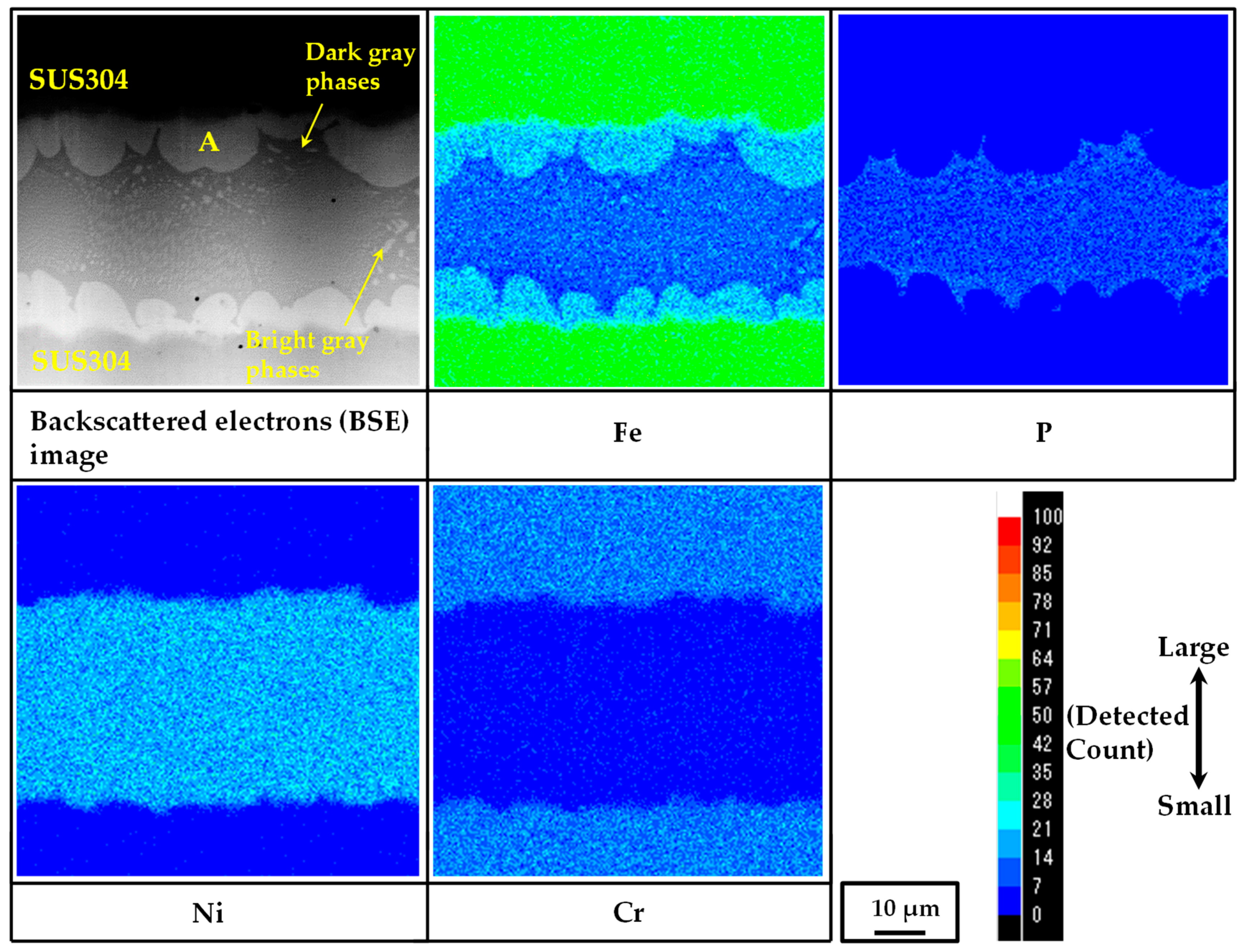
3.3. Microstructure Observation of Brazed Joint

Figure 6 shows the EPMA mapping analysis results for the brazed joint using the Ni-11P plated layer as the filler metal. The Ni and P elements are homogeneously distributed between the SUS304 plates. Also, the filler metal shows good bondability without voids or flaws in the brazed zone. The bright gray phases (A), which exist at the brazed interfaces of the SUS304 plates, were formed by the dissolution of the component element of the SUS304 plates into the molten filler metal [3,17]. The chemical composition of these phases was determined by EPMA and the result is given in Table 2. It was found that Ni and Fe are the main components. In addition, a small amount of Cr is contained in those phases. Figure 7 shows the isothermal section of the Fe-Ni-Cr ternary phase diagram at 25 °C, which was calculated by Thermo-Clac 2017a (using SSOL6: SGTE Alloy Solutions Database v6.0). In the figure, the chemical composition of point A shown in Table 2 is also plotted. Since the composition of P is 2.0 mol%, it is ignored and the compositions of only Fe, Ni, and Cr are expressed in percentage in the plot. From Figure 7, the bright gray phases shown in the BSE image in Figure 6 were identified as Fe-Ni-Cr solid solution.
Moreover, there are two types of phases in the brazed filler zone, dark gray and the bright gray phases. The BSE image shows that these two types of phases mix together in the brazed filler zone. In this study, both phases are too small to perform a chemical composition analysis. Nevertheless, the elemental distribution shows that P does not concentrate in the regions where the bright gray phases exist. Moreover, Fe and Ni are highly concentrated in the same regions. This means that the structure of these bright gray phases appears to be the same as that of the phase corresponding to point A. It has been reported that P mainly concentrates in the brazed filler zone owing to its low diffusion and low solubility into the matrix metal [3]. Thus, the dark gray phases are inferred to be the P-containing phases. To obtain a deeper understanding of these phases, further study, such as the XRD analysis of the brazed joint, is required.

3.4. Shear Test

The shear strength is an important criterion for the quality of a brazed joint. Four brazed joint specimens were prepared for the shear test. The average shear strength of the brazed joints obtained was determined to be 47.3 MPa. The standard deviation of the shear strength was 4.35 MPa, indicating that the shear strength of the brazed joint with the electroplated Ni-11P filler alloy is relatively stable. Takayama et al. [18] studied the joint strength of SUS304 brazed with BNi-2 filler metal for use in a heat exchanger. The shear strength of the brazed joint was approximately 100 MPa at 1040 °C. Wu et al. [19] reported that the shear strength of the brazed joint with NiCrP filler metal increased from 36 MPa at 980 °C to 137 MPa at 1040 °C, i.e., the shear strength increases with the brazing temperature. Although the shear strength obtained in this study is low, the brazed joint has excellent quality in terms of the absence of voids and flaws. The shear strength obtained in this study seems to correspond to that of the Ni-11P alloy and it has a meaningful guiding role in practical terms.
The fracture morphology of the brazed joint was observed by SEM. The result is shown in Figure 8a. The bright gray phases and the brazed filler zone were observed on the fractured surface, indicating that failure occurred in the brazed filler zone. Figure 8b shows an optical micrograph of the cross section of the fractured joint. A similar fracture mode was observed. As mentioned above, the P-containing phases were mainly concentrated in the brazed filler zone. These phases are brittle compounds and thus they appear to reduce the strength of the brazed joints.

4. Conclusions

In this study, a Ni-P alloy plated layer was fabricated on the surface of a SUS304 plate to replace a conventional foil or paste filler metal. Moreover, the microstructure and joint strength of the brazed joint with the electroplated Ni-P layer were investigated. The obtained results are as follows:
  • A Ni-11 wt.% P electroplated layer of 20 μm thickness was formed on the surface of the SUS304 plate in the case of 0.4 M H3PO3 in the bath, a current density of 2.0 A/dm2 and a plating time of 90 min.
  • The average shear strength of the brazed joints was determined to be 47.3 MPa.
  • Fracture occurred in the brazed filler zone where the brittle P-containing compounds existed.
  • The brazing filler metal formed by electroplating was homogeneously distributed between the SUS304 plates after brazing. This means that the electroplated Ni-P layer can be used as a brazing filler metal for SUS304.

Author Contributions

Writing—original draft, S.L.; writing—review & editing, S.L. and I.S.; conceptualization, I.S., J.H., T.W. and S.A.; formal analysis, S.L., A.H. and M.I.; investigation, M.I. and A.H.; methodology, I.S. and S.A.; project administration, I.S.; resources, I.S., J.H. and T.W.; supervision, I.S.

Funding

This research was funded by the Japan Science and Technology Agency (JST) A-STEP program.

Acknowledgments

This study was partially supported by the A-STEP Stage І industrial needs response type program of JST (Japan Science and Technology Agency).

Conflicts of Interest

The authors declare no conflict of interest.

References

  1. Yin, Y.-S. Brittleness of brazed seam for nickel-based filler metals and its influence factors. Trans. China Weld. Inst. 1997, 18, 4–10. [Google Scholar]
  2. Tung, S.K.; Lim, L.C.; Lai, M.O. Solidification Phenomena in nickel base brazes containing boron and silicon. Scr. Mater. 1996, 34, 763–769. [Google Scholar] [CrossRef]
  3. Zorc, B.; Kosec, L. Comparison of brazed joints made with BNi-1 and BNi-7 nickel-base brazing alloys. Rev. Metal. Madr. 2000, 36, 100–107. [Google Scholar] [CrossRef] [Green Version]
  4. Matsu, K. Brazing of Ni based brazing filler metals and the latest trend. Weld. Technol. 2011, 59, 54–57. [Google Scholar]
  5. Shohji, I.; Arai, S.; Kano, N.; Otomo, N.; Uenishi, M. Development of Cu brazing sheet with Cu-P composite plating. Key Eng. Mater. 2007, 353–358, 2025–2028. [Google Scholar] [CrossRef]
  6. Hamlyn-Harris, J.H.; St. John, D.H.; Sood, D.K. Amorphization of nickel and Ni-P alloys by ion implantation. Mater. Sci. Eng. A 1991, 147, 201–210. [Google Scholar] [CrossRef]
  7. Bagley, B.G.; Turnbull, D. The preparation and crystallization behaviour of amorphous nickel-phosphorous thin films. Acta Metal. 1970, 18, 857–862. [Google Scholar] [CrossRef]
  8. Peeters, P.; Hoorn, G.V.D.; Daenen, T.; Kurowski, A.; Staikov, G. Properties of electroless and electroplated Ni-P and its application in microgalvanics. Electrochim. Acta 2001, 47, 161–169. [Google Scholar] [CrossRef]
  9. Feng, L. Commercial Process for Electroplating Nickel-Phosphorous Coatings. U.S. Patent 20040031694A1, 19 February 2004. [Google Scholar]
  10. Morikawa, T.; Nakade, T.; Yokoi, M.; Fukumoto, Y.; Iwakura, C. Electrodeposition of Ni-P alloys from Ni-citrate bath. Electrochim. Acta 1997, 42, 115–118. [Google Scholar] [CrossRef]
  11. Seo, M.H.; Kim, J.S.; Hwang, W.S.; Kim, D.J.; Hwanf, S.S.; Chun, B.S. Characteristics of Ni-P alloy electrodeposited from a sulfamate bath. Surf. Coat. Technol. 2004, 176, 135–140. [Google Scholar] [CrossRef]
  12. Engelhaupt, D.; Ramsey, B. Nickel Cobalt Phosphorous Low Stress Electroplating. U.S. Patent 20020164262A1, 7 November 2002. [Google Scholar]
  13. Li, C.S.; Lee, C.Y.; Chen, F.J.; Chie, C.T.; Lin, P.L.; Chung, W.C. Electrodeposition of nickel-phosphorous alloy from sulfamate baths with improved current efficiency. J. Electrochem. Soc. 2006, 153, 387–392. [Google Scholar]
  14. Ma, C.B.; Cao, F.H.; Zhang, Z.; Zhang, J.Q. Electrodeposition of amorphous Ni-P coatings onto Nd-Fe-B permanent magnet substrates. Appl. Surf. Sci. 2006, 253, 2251–2256. [Google Scholar] [CrossRef]
  15. Harris, T.M.; Dang, Q.D. The mechanism of phosphorus incorporation during the electrodeposition of nickel phosphorus alloys. J. Electrochem. Soc. 1993, 140, 81–83. [Google Scholar] [CrossRef]
  16. Uttam, K.C.; Ajay, B.; Sudesna, R.; Soobhankar, P. Evaluation of Ni-Cr-P coatings electrodeposited on low carbon steel bipolar for polymer electrolyte membrane fuel cell. Int. J. Hydrogen Energry 2018, 43, 23430–23440. [Google Scholar]
  17. Haichuan, S.; Zhishui, Y.; JongRae, C. A study on the microstructure and properties of brazing joint for Cr18-Ni8 steel using a BNi7+9%Cu mixed filler metal. Vacuum 2018, 151, 226–232. [Google Scholar]
  18. Takayama, S.; Arikura, Y.; Shohji, I.; Nakazawa, T.; Matsumoto, K.; Hikita, M. Joint Strength and Microstructure of SUS304 Brazed with Nickel-base Filler Metal for Heat Exchangers. J. Jpn. Inst. Met. 2004, 68, 130–133. [Google Scholar] [CrossRef] [Green Version]
  19. Wu, N.; Li, Y.; Wang, J.; Puchkow, U.A. Vaccum brazing of super-Ni/NiCr laminated composite to Cr18-Ni8 steel with NiCrP filler metal. J. Mater. Process. Technol. 2012, 212, 794–800. [Google Scholar] [CrossRef]
Figure 1. Schematic illustration of the plating equipment.
Applsci 09 01094 g001
Figure 2. Geometry and dimensions of brazed joint specimen.
Applsci 09 01094 g002
Figure 3. Effect of H3PO3 concentration on P content and thickness of Ni-P plated layer (C.D.: 2.0 A/dm2, plating time: 90 min).
Applsci 09 01094 g003
Figure 4. XRD diffraction patterns of Ni-11P plated layer.
Applsci 09 01094 g004
Figure 5. SEM micrographs of surface morphology of plated layers. The plated layers were obtained in the bath containing 0.5 M H3PO3, with: (a) C.D.: 1.0 A/dm2, plating time: 180 min and thickness: 18 μm; (b) C.D.: 2.0 A/dm2, plating time: 90 min and thickness: 15 μm; (c) C.D.: 4.0 A/dm2, plating time: 40 min and thickness: 16 μm.
Applsci 09 01094 g005
Figure 6. EPMA mapping analysis results for brazed joint with Ni-11P plated layer. The plated layers used for brazing tests were obtained in the bath containing 0.4 M H3PO3 in the case of a current of 2.0 A/dm2 and a plating time of 90 min.
Applsci 09 01094 g006
Figure 7. Phase diagram of Fe-Ni-Cr at 25 °C.
Applsci 09 01094 g007
Figure 8. Fracture mode observation of brazed joint.
Applsci 09 01094 g008
Table 1. Bath composition and concentration for Ni-P alloy electrodeposition.
CompositionConcentration
NiSO4·6H2O1.0 M
NiCl2·6H2O0.2 M
H3BO30.5 M
H3PO30.12–0.5 M
C6H5Na3O70.5 M
Table 2. Chemical composition of point A in brazed joint.
PointElement Composition (mol%)Possible Phase
NiPFeCr
A41.32.048.18.6Fe-Ni-Cr solid solution

