Article

An Improved A-Star Algorithm Considering Water Current, Traffic Separation and Berthing for Vessel Path Planning

1
State Key Laboratory of Information Engineering in Surveying, Mapping and Remote Sensing, Wuhan University, Wuhan 430079, China
2
School of Remote Sensing and Information Engineering, Wuhan University, Wuhan 430079, China
3
National Engineering Research Center for Water Transport Safety, Wuhan University of Technology, Wuhan 430063, China
*
Author to whom correspondence should be addressed.
Appl. Sci. 2019, 9(6), 1057; https://doi.org/10.3390/app9061057
Submission received: 14 February 2019 / Revised: 9 March 2019 / Accepted: 10 March 2019 / Published: 13 March 2019

Abstract

:
A traditional A-Star (A*) algorithm generates an optimal path by minimizing the path cost. For a vessel, factors of path length, obstacle collision risk, traffic separation rule and manoeuvrability restriction should be all taken into account for path planning. Meanwhile, the water current also plays an important role in voyaging and berthing for vessels. In consideration of these defects of the traditional A-Star algorithm when it is used for vessel path planning, an improved A-Star algorithm has been proposed. To be specific, the risk models of obstacles (bridge pier, moored or anchored ship, port, shore, etc.) considering currents, traffic separation, berthing, manoeuvrability restriction have been built firstly. Then, the normal path generation and the berthing path generation with the proposed improved A-Star algorithm have been represented, respectively. Moreover, the problem of combining the normal path and the berthing path has been also solved. To verify the effectiveness of the proposed A-Star path planning methods, four cases have been studied in simulation and real scenarios. The results of experiments show that the proposed A-Star path planning methods can deal with the problems denoted in this article well, and realize the trade-off between the path length and the navigation safety.

1. Introduction

The autonomous surface vessel (ASV) technologies have grown rapidly and obtained more attention than ever both in military and commercial applications [1]. Among them, path planning in complex navigation area is one of most difficult and challenging topics that need to be developed. The aim of path planning is to find the optimal navigation path from the start location to the destination location [2]. Generally, path planning can be divided to two classes, i.e., global path planning and local path planning (real-time) [3]. A global path planner usually calculates paths off-line in static environments with stationary obstacles. In contrast, a local path planner usually calculates paths on-line in dynamic environments with moving obstacles. For the global planning, path length, risk factor, dynamic constraint, etc. should be considered at the same time. Specifically, current effect and navigation rules should also be included during the path planning for a vessel. In this article, we try to propose a global path planning method to satisfy the requirements of safety and efficiency for autonomous surface vessel. For a vessel, especially an autonomous surface vessel, factors of the path length, the obstacle collision risk, the traffic separation rule and the manoeuvrability restriction should be all taken into account when a path is planned for navigation. To solve these problems, a lot of studies for vessel path planning have been conducted. For instance, Szlapczynsk reported a ship route finding method with turn penalties and collision avoidance [4]; Kim et al. put forward a grid map-based path planning method with the kinematic constraint of the vessels [5]; Lyu et al. proposed a path-guided hybrid artificial potential field (PGHAPF) method to generate adaptive, collision-free and International Regulations for Preventing Collisions at Sea (COLREGS)-constrained paths in restricted waters [6,7]. However, the majority of path planning methods did not consider the current effect, berthing requirements and traffic separation rule together much. In recent years, Ma et al. proposed a dynamic augmented multi-objective particle swarm optimization (PSO) algorithm to obtain a path considering the path length, smoothness, economical efficiency and safety for unmanned surface vehicles [8]. Though this algorithm can get good performance of path planning, the PSO based method usually has the possibility of trapping in a local optima and the berthing requirements were not taken into account. For the berthing problem during path planning, Lee et al. proposed an EEA* algorithm considering hydrodynamic effects, angular constraint and head angle confinement at the goal point [9]. The head angle confinement could be a good attempt to solve the berthing problem, which, however, cannot guarantee the availability of the berthing path accord to the instructions of berthing in [10]. To obey the traffic separation rule for path planning, on the basis of the research of [4], Szlapczynski proposed an improved Evolutionary Algorithms (EA) method considering the Traffic Separation Schemes (TSS) [11]. We think that these attempts for solving the vessel path planning problems are beneficial. However, the demands of the vessel path planning proposed in this article have not been all satisfied, e.g., the risk of an obstacle in the upstream of current should be higher than that in the downstream of current, a berthing path should be generated considering the current effects, and the traffic separation rule should be modelled as a risk of path planning.
Grid map-based global path planning algorithms have been applied frequently and widely because their advantages in computation time and avoidance of local optimum [12]. A Dijkstra path planning algorithm based on grid map was first proposed in [13], which is to find the shortest paths between nodes in a graph. Dijkstra algorithm creates an open list and a closed list to denote the next alternative nodes and the selected nodes, respectively. A node in the open list will be transferred to the closed list when the distance from the start node is less than the best path so far [14]. In consideration of low search efficiency of Dijkstra path planning algorithm, an improved algorithm extended from Dijkstra algorithm, i.e., A-Star (A*) algorithm, was introduced by [15]. In contrast to the Dijkstra algorithm, A-Star algorithm transfers a node in the open list to the closed list by introducing the node potential that is the underestimate of the remaining distance to the destination node. A-Star algorithm has higher efficiency mainly because the node potential gives the direction to the destination node. A-Star algorithm forms the backbone of vehicle navigation systems, which has been used for robots, road vehicles, unmanned aerial vehicles, humans, etc. [2,14,16,17,18]. A traditional A-Star path planning algorithm generates an optimal path only by minimizing the path length in a grid map. Improvements for the A-Star algorithm have been done all the time. Bell proposed a Hyperstar algorithm based on A-Star approach for risk averse vehicle navigation [14]. Pochmara et al. improved the A-Star to decrease the computer calculation cost [19]. Fernandes et al. presented an enhanced A-Star algorithm capable of generating smooth and feasible paths considering orientation restrictions [2]. These improvements for the A-Star algorithm have solved several specific problems and widen the application areas. However, for the path planning of vessels, the A-Star and the A-Star based methods still need to be improved to generate safer and more efficient paths.
This study presents an improved A-Star based global path planning method to satisfy the requirements of the economy (path length), the obstacle avoidance, the traffic separation rule, the berthing and the manoeuvrability restriction considering the water current effects at the same time. The remainder of this article is organized as follows. Risks of the obstacles, the traffic separation, the berthing, manoeuvrability restriction are modelled in Section 2. In Section 3, an improved A-Star path planning algorithm considering risk models is proposed. In Section 4, four simulation case studies are carried out to verify the performance of the proposed methods for the normal path planning, berthing path planning and combined path planning, respectively. In the Section 5, the conclusions and future directions are presented.

2. Risk Modelling

During path planning, to find a shortest waterway is not the ultimate goal for a vessel because the safety of the vessel usually obtains more attention than the operation efficiency. However, existing path planning algorithms usually ignored the impact on the vessel safety when a vessel voyages nearby obstacles, such as bridge pier, shore, other vessels, port, etc., when the water current speed is large enough to be considered, when the traffic separation has been carried out, or when a vessel is for berthing. Hence, it is necessary to build relevant risk models to denote the impacts of these factors. In this section, we propose the four risk models designed for the obstacles, traffic separation, berthing and manoeuvrability, respectively.

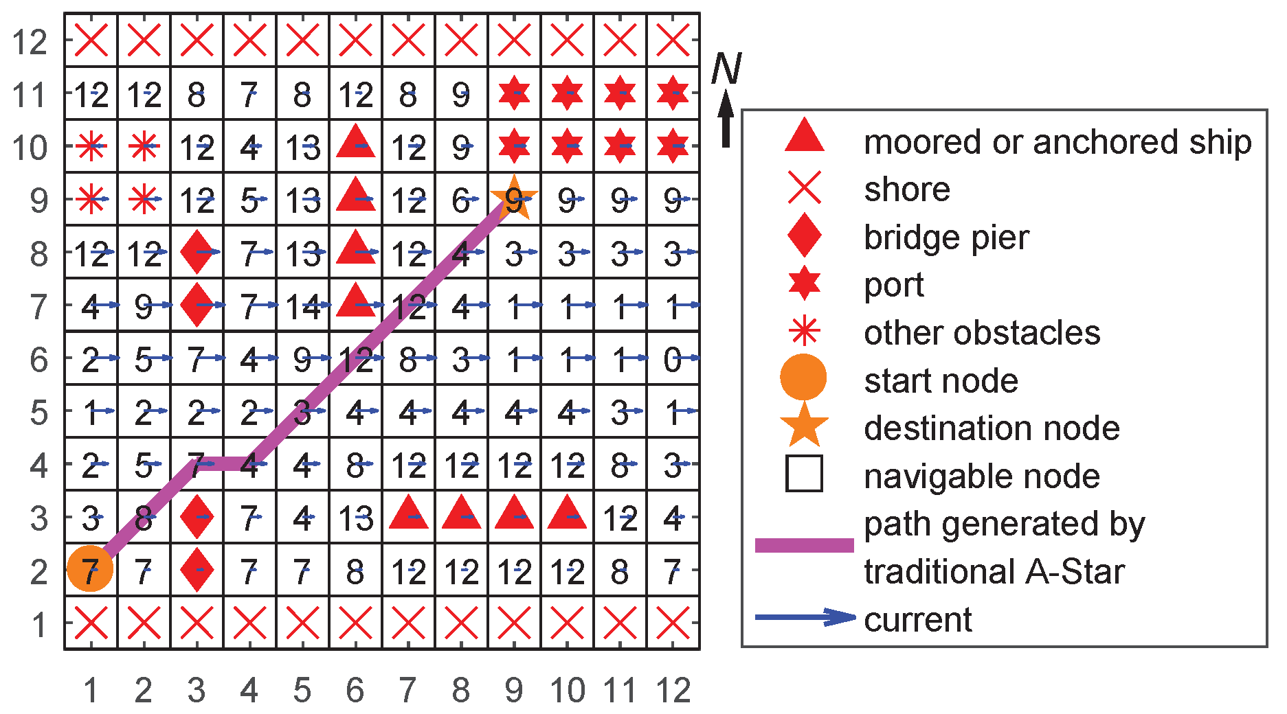
2.1. Obstacle Modelling With Current

The traditional A-Star algorithm can generate an optimal path with keeping off the obstacle nodes, which shown in Figure 1. From Figure 1, it can be seen that the generated path could be very close to obstacles to guarantee the path shortest. However, if this path is adopted by a sailing vessel as the planning route, the vessel will have a high risk to collide the obstacles. Meanwhile, the current will also increase the collision risk if the current pushes the vessel to approach one of obstacles. Therefore, it is indispensable to consider both keeping an appropriate distance from obstacles and current influence during path planning.
The obstacles for vessel can be divided into 5 types, namely, bridge pier, shore, vessel, port, and others. Different types of obstacles have different risks for vessel navigation. The risk degree r o m , n of navigable node N m nearby obstacle node O n is defined as follows:
r o m , n = e d a + c m v m d ,
where d stands for the Euclidean distance from an navigable node N m to the obstacle node O n . a stands for the risk coefficient for different types of obstacles. In this article, a is assigned as 5 , 5 , 3 , 4 , 3 for bridge pier, shore, vessel, port, and others. v m stands for the current velocity. c m stands for the direction coefficient, which is as follows:
c m = cos ϕ c ϕ g , cos ϕ c ϕ g < 0 0 , cos ϕ c ϕ g 0 ,
where, ϕ c [ 0 , 2 π ) is the current direction toward the true North; ϕ g [ 0 , 2 π ) is the node direction relative to obstacle node O n toward the true North, i.e., the direction of vector N m O n toward the true North.
A grid map considering the obstacle with current is represented in Figure 2. In Figure 2, the number in a navigable node denotes the risk degree, and the direction and length of an arrow denote the current direction and velocity, respectively. A navigable node N m could have k risk degree values if there exist k obstacle nodes nearby N m according to Equation (1). In this case, the maximum one will be selected as the final risk degree. Therefore, the final risk degree of node N m , r o m , is defined as follows:
r o m = max r o m , 1 , r o m , 2 , , r o m , k ,
In Figure 2, the path is generated by the traditional A-Star algorithm, which chooses an optimal path node without considering the risk degree of the path node.

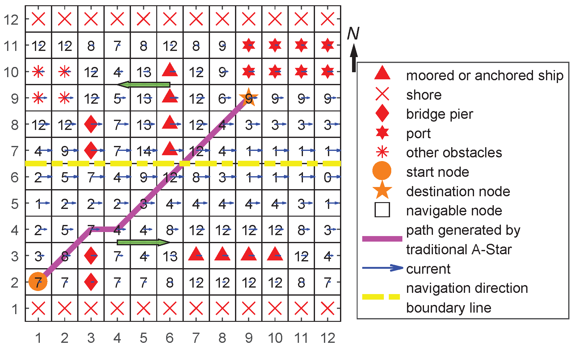
2.2. Traffic Separation Modelling

Similar to the lane separation for vehicle driving on the road, a vessel also needs to obey the traffic separation rule in the waterway to decrease the risk of collision and increase the operation efficiency. Based on the traffic separation rule, a risk model of traffic separation for a navigable node N m is built as:
r s m = 1 cos ϕ n ϕ r , 0 < cos ϕ n ϕ r 1 1 α cos ϕ n ϕ r , 1 cos ϕ n ϕ r 0 ,
where ϕ n [ 0 , 2 π ) is the navigation direction by rule toward the true North. Assume that the path is defined as N 1 , , N m , , , ϕ r [ 0 , 2 π ) at node N m is the direction of the path vector N m 1 N m toward the true North. When the navigation direction is consistent with the path vector direction, i.e., 0 r s m < 1 ; otherwise, 1 r s m 1 + α . The grid map considering traffic separation is shown in Figure 3. From Figure 3, the path generated by the traditional A-Star algorithm cannot guarantee the planning path to be consistent with the navigation direction by rule.

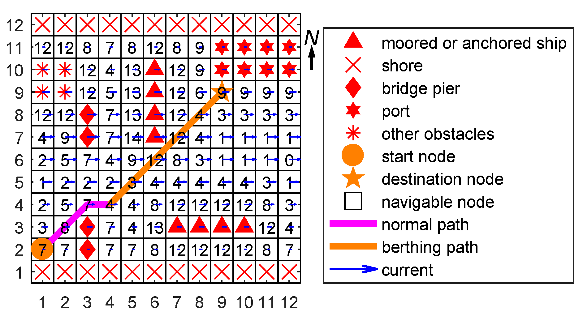
2.3. Berthing Modelling Considering Current

When a vessel needs to berth at a port or an anchorage in a waterway with a non-ignorable current, the vessel usually berths into the current, which means the vessel motion direction is opposite to the current direction. The reasons for it are summarized as: (1) it will give the vessel the advantage of relatively high speed through the water with a reduced speed over the ground; (2) it can be used to push the vessel alongside [10]. Figure 4 shows the berthing path is generated by the traditional A-Star algorithm. From Figure 4, the vessel motion direction planed by the traditional A-Star algorithm is the same as the current direction, which is not beneficial for the berthing. Hence, if the destination node is a berthing node, the berthing path should be considered.
The generated path with a berthing destination node consists of the normal path P n and the berthing path P b . The berth path P b should consider the current effect. In contrast to the normal A-Star algorithm, the berthing path has no specific destination node with the berth node as the start node. Therefore, how to generate a berth path without a destination node is a key point to deal with.
The berthing risk of a navigable node N m , r b e m , is modelled as follows:
r b e m = c s m 1 + cos ϕ n ϕ r ,
where r b e m 0 , and c > 0 is a constant coefficient. s m = 0 , 1 , , N b e is the sequence number of node N m from the berth node, in which N b e is the node number of the berthing path. ϕ n and ϕ r are defined in Equation (4). The specific procedure to generate the berthing path will be described in Section 3.2.2.

2.4. Manoeuvrability Restriction Modelling

The minimum turning radius of a vessel represents the turning ability of the vessel when following a predefined path. Actually, this ability is restricted to the manoeuvrability of the vessel. If the restriction of turning radius is not set, the generated path could not be followed by the vessel and the risk of collision and stranding could even happen.
Assume that P i 1 , P i , P i + 1 are the continuous nodes of a path, which is shown in Figure 5.
θ [ 0 , π ) is the included angle between line P i 1 P i and line P i P i + 1 . l is the shorter length between the length of P i 1 P i and the length of P i P i + 1 . A circle is built through node P i 1 , which is tangent to line P i 1 P i and line P i P i + 1 . Then the radius of the circle, R i , is obtained:
R i = l tan θ 2 .
If the minimum turning radius of the vessel R 0 is greater than R i , it means that the continuous nodes P i 1 , P i , P i + 1 is not available for this vessel, and vice versa. Hence, a risk model for manoeuvrability restriction is defined as follows:
r m m = b 1 + R i R 0 , R 0 > R i 0 , R 0 R i ,
where b > 0 is a constant coefficient.

3. Improved A-Star Algorithm

In consideration of the limitations of the traditional A-Star algorithm applying in the path planning of vessels, an improved A-Star algorithm is studied in this section based on the risk models built in Section 2. The traditional algorithm is introduced first, and then an A-Star algorithm considering risk modelling is presented.

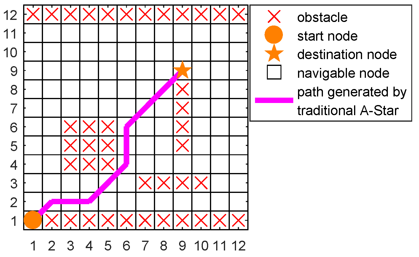
3.1. Traditional A-Star Algorithm

A-Star algorithm was first proposed and described in detail in [15]. The A-Star algorithm aims to find a path from the start node ( N s t a r t ) to the destination node ( N d e s t ) with the smallest cost, e.g., least distance. The flowchart of the traditional A-Star algorithm is denoted in Algorithm 1.
Algorithm 1 Traditional A-Star algorithm ( N s t a r t N d e s t )
1:
Mark N s t a r t as o p e n l i s t .
2:
while o p e n l i s t do
3:
 Select the open node N i from the o p e n l i s t whose value of evaluation function f N i is smallest.
4:
if N i = N d e s t then
5:
  return “path is found”.
6:
else
7:
  Mark N i as c l o s e l i s t .
8:
  if Successor N i j of node N i does not belong to c l o s e l i s t or o b s t a c l e node then
9:
   Mark N i j as o p e n l i s t and calculate f N i j .
10:
   if N i j belongs to o p e n l i s t and f N i j is smaller than f N m j when N m was marked as c l o s e l i s t then
11:
     f N j = f N i j and set parent node of N j as N i .
12:
   end if
13:
  end if
14:
end if
15:
end while
16:
return “path is not found”.
The evaluation function f N i of N i is defined as:
f N i = g N i + h N i ,
where g N i is the cost of the path from N s t a r t to N i , and h N i is a heuristic function that estimates the cost of the cheapest path from N i to N d e s t . h N i can be Euclidean distance (Manhattan distance or Chebyshev distance) from N i to N d e s t , or other functions denoting the cost from N i to N d e s t as in [9]. Please note that in contrast to the A-Star algorithm, the Dijkstra algorithm has no heuristic function that can accelerate the rate of finding an optimal path. The Euclidean distance is selected as h N i in this article.

3.2. A-Star Algorithm Considering Risk Models

If an A-Star algorithm is used to the path planning for vessels. Theoretically, the traditional A-Star algorithm can find the shortest path, which is not nevertheless the optimal path for vessels in some scenarios. In this section, we try to consider the path length, the path risk and navigation rules simultaneously during the path planning. According to the destination, a normal path generation and berthing path generation are introduced with a non-berthing destination and berthing destination.

3.2.1. Normal Path Generation of Vessels

To satisfy the requirements of considering risks for vessel path planning, model (8) needs to be modified. Here, g N i is redesigned as:
g n N i = g N i + τ n r n N i ,
where g n N i is the newly defined cost of the path from N s t a r t to N i . τ n > 0 is a constant coefficient. g N i is defined as:
g N i = k = 1 p 1 d k ,
where p 1 is the node amount from N i to N s t a r t , i.e., N i , N i . p a r e n t , N i . p a r e n t . p a r e n t , …, N s t a r t , in which N . p a r e n t represents the parent node of N.
d k is the Euclidean distance between kth node to ( k + 1 ) th node, where k stands for the node sequence from the start node. To be specific, assuming that the coordinates of kth node is x k , y k , then d k is as follows:
d k = x k x k + 1 2 + y k y k + 1 2 .
r n N i is the risk function, which is as follows:
r n N i = r o i + r s i + r m i ,
where r o i , r s i and r m i are defined in Equations (3), (4) and (7), respectively. Please note that r s = 0 if traffic separation rule is not carried out in certain waterway.
A new evaluation function f n N i is defined as:
f n N i = g n N i + β n h n N i ,
where β n > 0 is a constant coefficient. In contrast with (8), β n is added to balance the weight between g n N i and h n N i . Assuming that the coordinates of N i are x N i , y N i and the coordinates of N d e s t are x N d e s t , y N d e s t , then h n N i is as follows:
h n N i = x N i x N d e s t 2 + y N i y N d e s t 2 .
The proposed A-Star algorithm of the normal path generation is presented as Algorithm 2.
Algorithm 2 Normal path generation with the improved A-Star algorithm ( N s t a r t N d e s t )
1:
Mark N s t a r t as o p e n l i s t .
2:
if the destination node is not the berthing one then
3:
if traffic separation rule is not carried out then
4:
   r s = 0 at any time.
5:
end if
6:
while o p e n l i s t do
7:
  Select the open node N i whose value of evaluation function f n N i is smallest.
8:
  if N i = N d e s t then
9:
   return “path P n is found”.
10:
  else
11:
   Mark N i as c l o s e l i s t .
12:
   if Successor N i j of node N i does not belong to c l o s e l i s t or o b s t a c l e node then
13:
    Mark N i j as o p e n l i s t .
14:
    Calculate r o j , r s j and r m j by (3), (4) and (7), respectively. Then, r n N i j = r o j + r s j + r m j .
15:
    if N i j belongs to o p e n l i s t and f n N i j is smaller than f n N m j when N m was marked as c l o s e l i s t then
16:
      f n N j = f n N i j and N j . p a r e n t = N i .
17:
    end if
18:
   end if
19:
  end if
20:
end while
21:
return “path P n is not found”.
22:
end if

3.2.2. Berthing Path Generation of Vessels

As previously mentioned, when the destination node is the berthing one, a specific path planning rule should be obeyed in order to guarantee the safety of vessels. The algorithm of generating berthing path P b described in Section 2.3 is presented in Algorithm 3, in which N b e r t h is the starting node of  P b .
The evaluation function for berthing path generation, f b N i , is defined as:
f b N i = g b N i + β b h b N i ,
where β b > 0 is a constant coefficient. h b N i = 0 at any time since the destination node is not known before the berthing path generation finishes. g b N i is as follows:
g b N i = g N i + τ b r b N i ,
where g N i = 0 at any time, τ b > 0 is a constant coefficient. r b N i is as follows:
r b N i = r o i + r b e i + r m i .
Please note that the traffic separation rule is not considered for the berthing path generation, i.e., r s = 0 at any time, because a vessel in the berthing process always finds the path that is against the current ignoring the traffic separation rule temporarily.
Combining (15), (16) and (17), f b N i can be denoted as:
f b N i = r o i + r b e i + r m i .
Please note that τ b = 1 and β b = 1 are both eliminated in (18) since g N i and h b N i are constant to 0.
Algorithm 3 Berthing path generation algorithm ( N b e r t h N d e s t )
1:
Mark N d e s t as o p e n l i s t .
2:
if the destination node is the berthing one then
3:
 Set the predefined number of berthing path nodes as q 0 .
4:
while o p e n l i s t do
5:
  Select the open node N i whose value of evaluation function f b N i is smallest.
6:
  Set N i as the berth node and N i N d e s t as the berth path P b . Count the number of the path P b nodes, which is denoted as q b .
7:
  if q b > = q 0 then
8:
   “path P b is found”.
9:
  else
10:
   Mark N i as c l o s e l i s t .
11:
   if Successor N i j of node N i does not belong to c l o s e l i s t or o b s t a c l e node then
12:
    Mark N i j as o p e n l i s t .
13:
    Calculate r o j , r b e j and r m j by (3), (4) and (7), respectively. Then, r b N i j = r o j + r b e j + r m j .
14:
    if N i j belongs to o p e n l i s t and f b N i j is smaller than f b N m j when N m was marked as c l o s e l i s t then
15:
      f b N j = f b N i j and N j . p a r e n t = N i .
16:
    end if
17:
   end if
18:
  end if
19:
end while
20:
return “path P b is not found”.
21:
end if

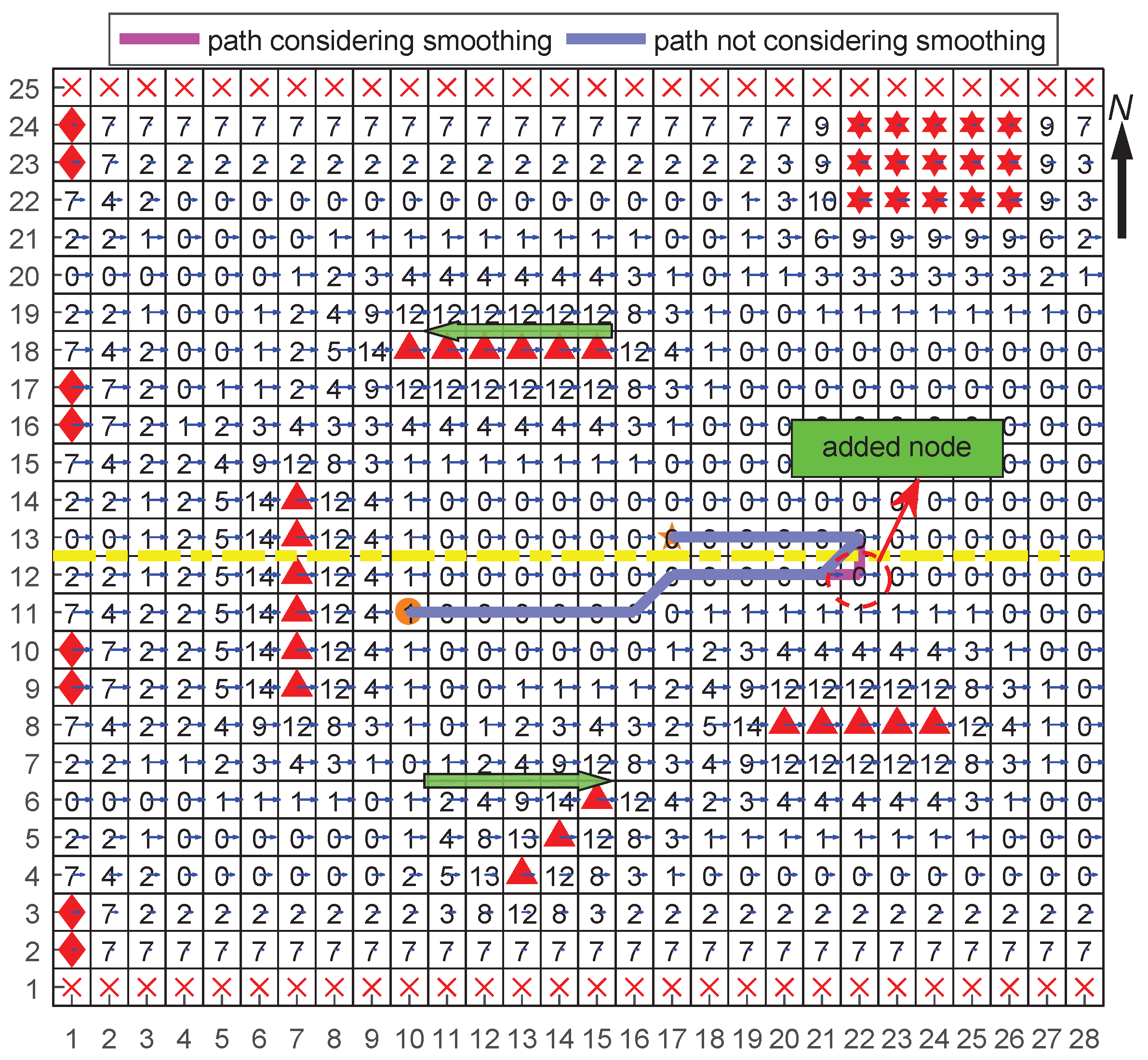
3.2.3. Combined Path Generation of Vessels

In most of path planning scenarios, the normal path and the berthing path both need to be generated. Therefore, it should be considered that how to combine the normal path and the berthing path. The main problem is that the manoeuvrability risk r m m defined in (7) could be high, which will increase the risk of collision or stranding when the connection node of the normal path and the berthing path is inappropriate. For instance, in Figure 6, the sharp turn could not be tracked well by the vessel. The distance between two adjacent nodes, l n , is usually relevant to the minimum radius of the vessel, R 0 . In this article, we set l n = R 0 .
The combined path P c consists of the normal path P n and the berthing path P b , i.e., P c = P n + P b . To avoid a sharp turn at node N b e r t h , i.e., R 0 > R b e r t h , where N b e r t h is the first node of P b , a new node can be added between N b e r t h and the second node of P b . As shown in Figure 7, a node is added to eliminate the sharp turn and make the generated path smooth enough be followed.
The algorithm of adding node or smoothing the combined path is denoted in Algorithm 4.
Algorithm 4 Smoothing the combined path algorithm ( P c = P n + P b )
1:
Define the last node and the last but one node of P n = N n 1 , , N n e , N b e r t h as N b e r t h and N b e respectively, and define the second node of P b = N b e r t h , N b 1 , as N b 1 , which is shown in Figure 7.
2:
Calculate r m b e r t h by (7).
3:
if r m b e r t h = = 0 then
4:
return “added node does not need. “
5:
end if
6:
if r m b e r t h > 0 then
7:
 The turn of N n e N b e r t h N b 1 is too sharp to track by the vessel.
8:
 Try to find a node from eight neighbourhood of N b e r t h except node N b 1 and node N n e that will be added to P b . The coordinates of N b e r t h is denoted as x N b e r t h , y N b e r t h .
9:
c o u n t = 0 .
10:
for i = 1 : 1 do
11:
  for j = 1 : 1 do
12:
   A candidate node N c x N b e r t h + i , y N b e r t h + j is selected to be verified.
13:
   if N c N b e r t h and N c N b 1 and N c is not an obstacle node and N c is not beyond the boundary of the grid map. then
14:
    Calculate r m 1 c of N b e r t h N c N b 1 and r m 1 b e r t h of N n e N b e r t h N c by (7).
15:
    Calculate r m 2 c of N c N b e r t h N b 1 and r m 2 b e r t h of N n e N c N b e r t h by (7).
16:
    if r m 1 ( 2 ) c = = 0 and r m 1 ( 2 ) b e r t h = = 0 then
17:
     Add N c x N b e r t h + i , y N b e r t h + j to a d d n o d e l i s t .
18:
     Calculate the danger risk r a d d c = r m 1 ( 2 ) c + r o 1 ( 2 ) c , where r o 1 ( 2 ) c is calculated by (3).
19:
      f a d d c = 1 ( 2 ) and add f a d d c to f l a g l i s t .
20:
      c o u n t = c o u n t + 1 .
21:
    end if
22:
   end if
23:
  end for
24:
  end for
25:
if c o u n t > 0 then
26:
  Obtain the danger risk list r a d d c n = r m c n + r o c n for node list N c n n = 1 , 2 , , c o u n t .
27:
  Select the node with the smallest value of r a d d from r a d d c n n = 1 , 2 , , c o u n t , i.e., N c min , and set N a d d = N c min .
28:
  if f a d d c min = = 1 then
29:
   Change P b to P b = { N b e r t h , N a d d , N b 1 , } and P c = P n + P b .
30:
  else
31:
   Change P n to P n = { N n 1 , , N a d d , N b e r t h } and P c = P n + P b .
32:
  end if
33:
  return “added node is found. “
34:
else
35:
  return “added node cannot be found. “
36:
end if
37:
end if

4. Case Study

To verify the effectiveness of the proposed improved A-Star path planning method, simulation experiments are conducted in this section. Firstly, a normal path is generated by the proposed A-Star algorithm in consideration of obstacle, traffic separation and manoeuvrability risk, and the performance of path planning is compared between the proposed A-Star method and traditional A-Star method. Then, the berthing path planning is realized by the proposed A-Star algorithm, and the berthing path is evaluated. The combination of the normal path and the berthing path is conducted by the proposed A-Star algorithm and the performance of the combined path is compared with the uncombined path. Finally, the proposed improved A-Star method is used to generate the path in a real scenario in Yangtze waterway.

4.1. Case 1: Normal Path Planning

During the normal path planning, the obstacle risk and the manoeuvrability restriction risk are always considered, and it depends on the traffic rule that whether the traffic separation risk is considered or not. In this case, all these types of risks are all taken into consideration.

4.1.1. Setup

To model the obstacle risk, related model parameters need to be determined. It is known that the current velocity near the shore is smaller than one far away from the shore. Hence, v m m / s at node N m is set as:
v m = 0.4 d s , d s 4 l n 2 , d s > 4 l n ,
where d s m is the vertical distance from node N m to the nearest shore node. Other parameters are shown in Table 1. The vessel starts from the start node N s t a r t ( 3 , 3 ) to the destination node ( 32 , 21 ) .

4.1.2. Results

The normal path generation performance with a traditional A-Star algorithm and an improved A-Star algorithm for vessels is shown in Figure 8. From Figure 8, it can be seen that the traditional A-Star algorithm generates the optimal path only by taking the shortest path length as the standard. On the contrary, the improved A-Star algorithm considers the path length, obstacle risk, the traffic separation rule and manoeuvrability restriction simultaneously. Specifically, the path length of the traditional A-Star algorithm and the improved A-Star algorithm is 34.0 and 38.1 , respectively. Generally, the improved A-Star algorithm will generate a longer path than the traditional A-Star algorithm.
The sum of path node obstacle risk for the traditional A-Star algorithm and the improved A-Star algorithm is 150 and 22, respectively. The path generated by the traditional A-Star algorithm has much higher risk to collide with obstacles. For instance, the vessel is too close to the bridge piers and other vessels, which could increase the collision risks enormously in Figure 8.
The path generated by the improved A-Star algorithm has taken into account the traffic separation rule, which decreases the risk of collision with other navigating vessels. Moreover, the manoeuvrability risk is also considered in the improved A-Star algorithm to avoid the vessel failing to track the generated path.
In summary, the improved A-Star algorithm can improve the navigating safety with slightly increasing the path length.

4.2. Case 2: Berthing Path Planning

4.2.1. Setup

As previously mentioned, a vessel should berth into the current when the vessel needs to anchor or berth at a port. In this case, the vessel starts from the node of N s t a r t 6 , 3 to the port whose node is N d e s t 32 , 21 . The node number of berthing path P b is set to 6. The other parameters are the same as Table 1. The performance of the berthing path planning is presented as Figure 9.

4.2.2. Results

In Figure 9, the path generated by the A-Star algorithm without considering the berthing path is hard to berth to the port because the vessel cannot be manipulated well if the current direction is consistent with the vessel sailing direction. When the berthing procedure is taken into account, the berthing path P b and the berthing node N b e r t h are obtained firstly according to Algorithm 3, specifically, the coordinates of N b e r t h are 37 , 18 . Then, the normal path P n can be generated with the destination node N d e s t = N b e r t h . Finally, P n and P b are combined to become the complete path P c .

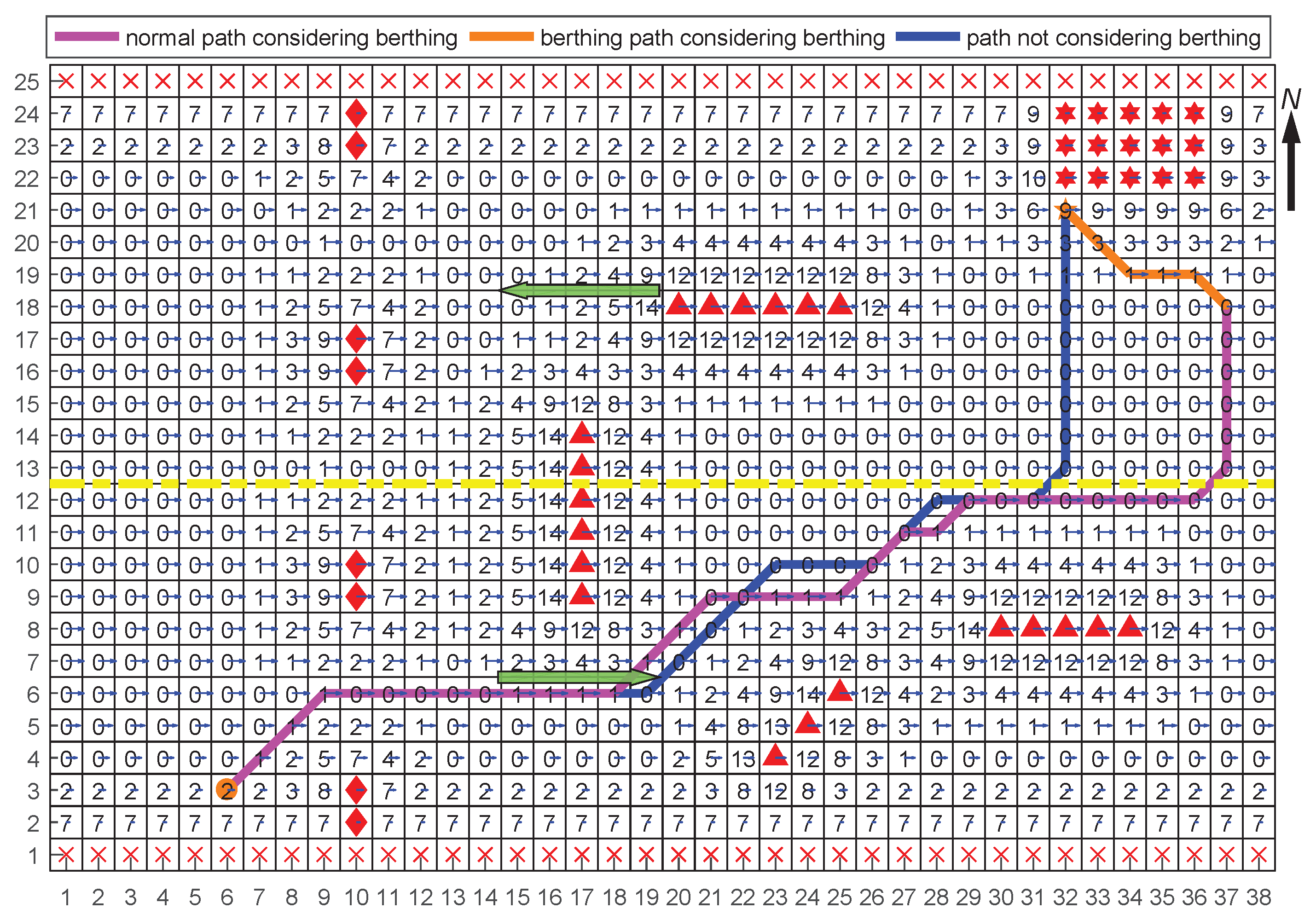
4.3. Case 3: Combined Path Planning

4.3.1. Setup

When combining normal path P n and berthing path P b , a sharp turn could encounter in the combination node, which will result in that the vessel cannot track the path because of the restriction of vessel’s manoeuvrability. In this case, the vessel needs to berth in an anchorage from node 10.11 to node 17 , 13 . The parameters are the same as Table 1 except the node range of x axis changes to 28. The comparison of path planning with considering smoothing the path or without considering smoothing the path is presented in Figure 10.

4.3.2. Results

As shown in Figure 10, a sharp turn appears when smoothing the path is not considered. The sharp turn is eliminated when the smoothing strategy denoted by Algorithm 4 is applied. When the number of candidates for the added node are more than one, a candidate node with the least risk r a d d defined in Algorithm 4 is selected.

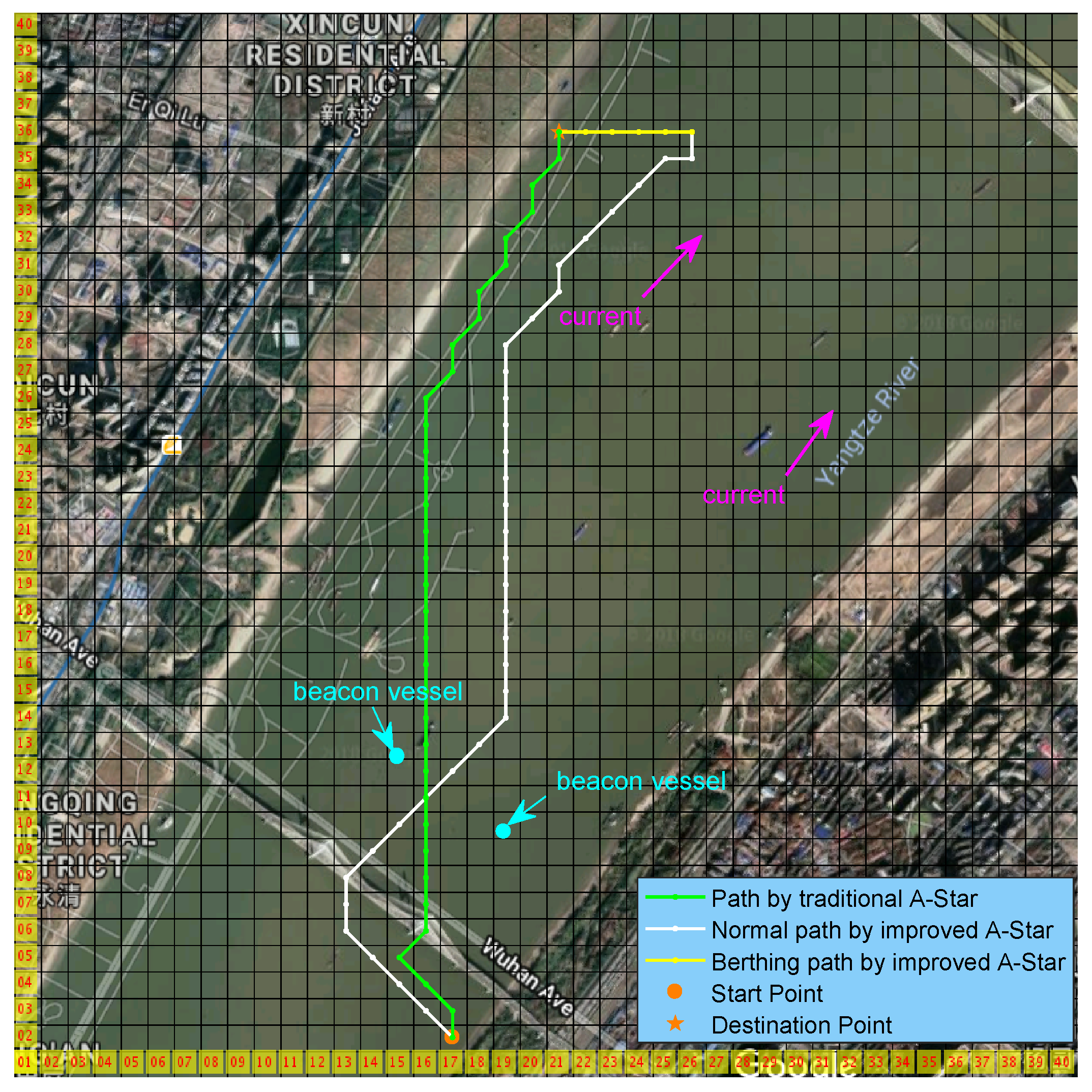
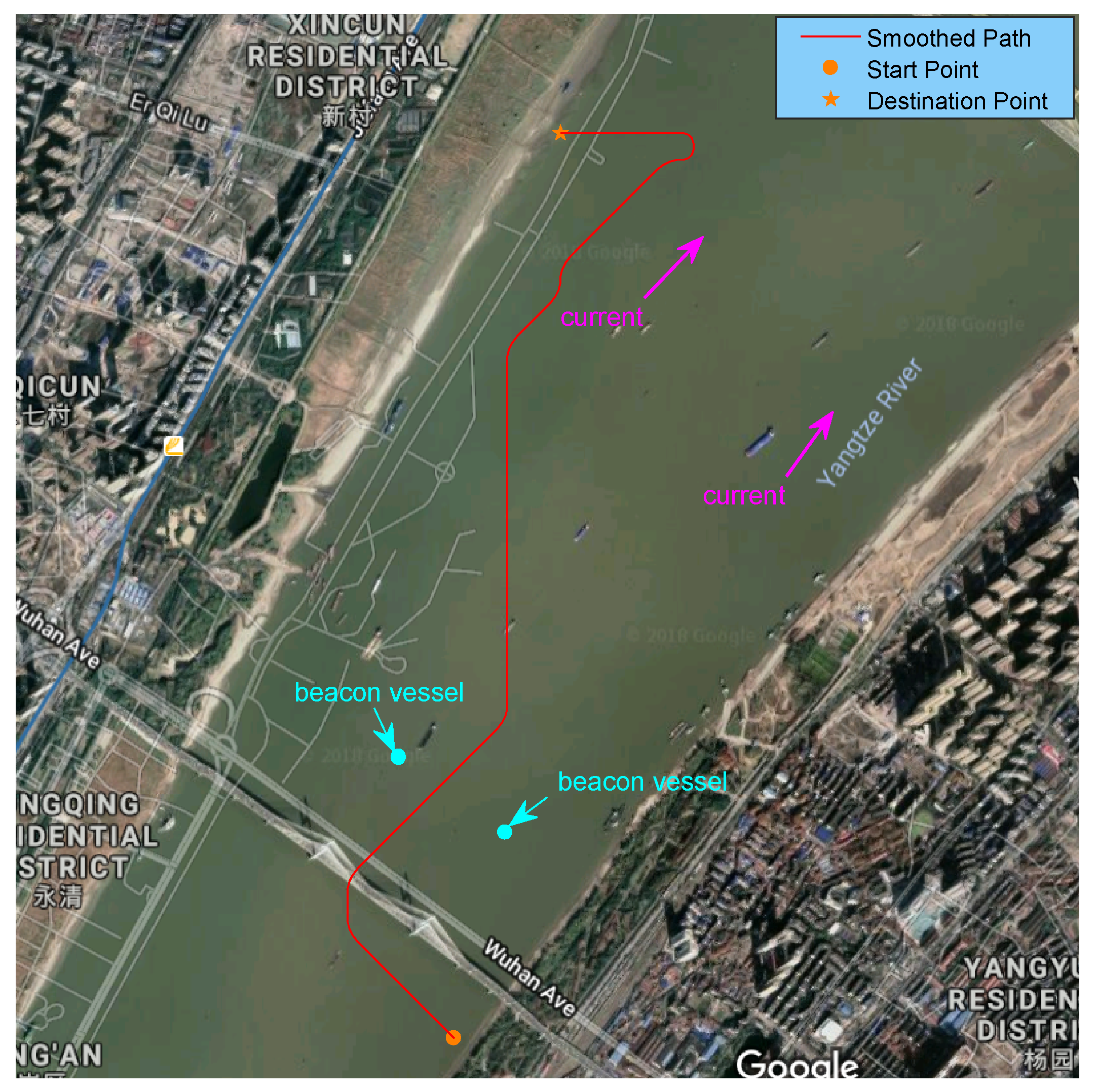
4.4. Case 4: Path Planning in Real Scenario

A real scenario, Wuhan waterway in Yangtze River, is selected to verify the effectiveness of the improved A-Star method in this case. In this scenario, a vessel is planned to navigate from one side of the river to the other side of the river in a bridge zone, which is shown in Figure 11. The navigable area for crossing bridge is indicated by the two beacon vessels, i.e., the middle area between the beacon vessel is navigable. To apply the proposed path planning method, the grid length, l n , is set as 50 m, and the minimum radius of vessel, R 0 , is set as 45 m. The latitude and longitude coordinates of the start point is ( 30 36 0.26 N, 114 19 23.4 E), and the latitude and longitude coordinates of the destination point is ( 30 37 35.9 N, 114 19 36.0 E). Please note that the traffic separation rule is not applied by the navigation rule in this waterway. Sailing vessels in this scenarios are not recognized as the obstacles because only moored or anchored vessels are considered as obstacles for the global path planning in this article. The other parameters are set the same as Case 1.
The paths planned with the proposed A-Star algorithm, which consists of the normal path and the berthing path, and the traditional A-Star algorithm are shown in Figure 11, respectively. From Figure 11, it can be seen that the traditional A-Star has high risk to collide with the bridge and cannot guarantee the safety of berthing. To verify that a heuristic algorithm, e.g., A-Star algorithm, has a higher efficiency than a non-heuristic algorithm. The computation time records for A-Star algorithm with the improved A-Star algorithm and the search algorithm without heuristic guide for this case are 935 ms and 1127 ms, respectively. It means that the algorithm without heuristic guide actually has a higher efficiency. The path smoothed with the uniform B-spline curve of order 3 for the improved A-Star algorithm is shown Figure 12. The path in Figure 12 can be set as a safety path that can be followed by a vessel.

5. Conclusions and Future Research

According to the defects of the traditional A-Star algorithm when it is used for vessel path planning, an improved A-Star algorithm has been proposed in this article. Firstly, the risk models of obstacles (bridge pier, moored or anchored ship, port, shore, etc.) with currents, traffic separation, berthing, manoeuvrability restriction have been built. Then, the procedure of the normal path generation and the berthing path generation with the proposed A-Star algorithm have been depicted, respectively. Moreover, the problem of combining the normal path and the berthing path has been also solved. Four cases have been studied to verify the effectiveness of the proposed A-Star algorithm. The simulation and real experiment results show that the proposed A-Star path planning methods can avoid the high risk of obstacle collision, obey the separation rule and meet the requirements of berthing for vessels. In a word, the proposed algorithms can realize the trade-off between the path length and the navigation safety.
In future work, wind and water depth can be also considered during vessel path following, because wind will affect the ship navigation safety and economical efficiency, and shallow water will increase the vessel stranding risk.

Author Contributions

Conceptualization, C.L. and Q.M.; Methodology, C.L.; Software, C.L.; Validation, C.L and S.X.; Writing-Original Draft Preparation, C.L.; Writing-Review and Editing, C.L., Q.M. and X.C.; Visualization, X.C. and S.X.; Funding Acquisition, C.L, Q.M. and X.C.

Funding

This research is supported by the China Postdoctoral Science Foundation (2018M632923), the Wuhan Science and Technology Project (2017010201010132), and the Fundamental Research Funds for the Central Universities (2042017KF0235).

Conflicts of Interest

The authors declare no conflict of interest.

References

  1. Wuthishuwong, C.; Traechtler, A.; Bruns, T. Safe trajectory planning for autonomous intersection management by using vehicle to infrastructure communication. EURASIP J. Wirel. Commun. Networking 2015, 2015, 33. [Google Scholar] [CrossRef]
  2. Fernandes, E.; Costa, P.; Lima, J.; Veiga, G. Towards an orientation enhanced Astar algorithm for robotic navigation. In Proceedings of the 2015 IEEE International Conference on Industrial Technology (ICIT), Seville, Spain, 18 June 2015; pp. 3320–3325. [Google Scholar]
  3. Raja, P.; Pugazhenthi, S. Optimal path planning of mobile robots: A review. Int. J. Phys. Sci. 2012, 7, 1314–1320. [Google Scholar] [CrossRef]
  4. Szlapczynski, R. A new method of ship routing on raster grids, with turn penalties and collision avoidance. J. Navig. 2005, 59, 27–42. [Google Scholar] [CrossRef]
  5. Kim, H.; Park, B.; Myung, H. Curvature path planning with high resolution graph for unmanned surface vehicle. In Proceedings of the Robot Intelligence Technology and Applications (RiTA); Springer: Gwangju, Korea, 2013; pp. 147–154. [Google Scholar]
  6. Lyu, H.; Yin, Y. Fast path planning for autonomous ships in restricted waters. Appl. Sci. 2018, 8, 2592. [Google Scholar] [CrossRef]
  7. Lyu, H.; Yin, Y. COLREGS-constrained real-time path planning for autonomous ships using modified artificial potential fields. J. Navig. 2018, 1–21. [Google Scholar] [CrossRef]
  8. Ma, Y.; Hu, M.; Yan, X. Multi-objective path planning for unmanned surface vehicle with currents effects. ISA Trans. 2018, 75, 137–156. [Google Scholar] [CrossRef] [PubMed]
  9. Lee, T.; Kim, H.; Chung, H.; Bang, Y.; Myung, H. Energy efficient path planning for a marine surface vehicle considering heading angle. Ocean Eng. 2015, 107, 118–131. [Google Scholar] [CrossRef]
  10. Murdoch, E. A Master’s Guide to Berthing; The Standard; Witherby & Company: Witherby, UK, 2004. [Google Scholar]
  11. Rafal, S. Evolutionary Sets of Safe Ship Trajectories Within Traffic Separation Schemes. J. Navig. 2013, 66, 65–81. [Google Scholar]
  12. Kim, H.; Kim, D.; Shin, J.U.; Kim, H.; Myung, H. Angular rate-constrained path planning algorithm for unmanned surface vehicles. Ocean Eng. 2014, 84, 37–44. [Google Scholar] [CrossRef]
  13. Dijkstra, E.W. A note on two problems in connexion with graphs. Numer. Math. 1959, 1, 269–271. [Google Scholar] [CrossRef] [Green Version]
  14. Bell, M.G.H. Hyperstar: A multi-path Astar algorithm for risk averse vehicle navigation. Transp. Res. Part B Methodol. 2009, 43, 97–107. [Google Scholar] [CrossRef]
  15. Hart, P.E.; Nilsson, N.J.; Raphael, B. A formal basis for the heuristic determination of minimum cost paths. IEEE Trans. Syst. Sci. Cybern. 1968, 4, 100–107. [Google Scholar] [CrossRef]
  16. Rahman, S.M.M.; Al-Arif, A.H.M.; Ferdous, I.; Nizami, M.S.H. Path planning for robotic boats in a rescue system. Int. J. Comput. Appl. 2012, 45, 50–57. [Google Scholar]
  17. Sathyaraj, B.M.; Jain, L.C.; Finn, A.; Drake, S. Multiple UAVs path planning algorithms: A comparative study. Fuzzy Optim. Decis. Mak. 2008, 7, 257–267. [Google Scholar] [CrossRef]
  18. Yao, J.; Lin, C.; Xie, X.; Wang, A.J.A.; Hung, C.C. Path planning for virtual human motion using improved A* star algorithm. In Proceedings of the Seventh International Conference on Information Technology: New Generations (ITNG), Las Vegas, NV, USA, 1 July 2010; pp. 1154–1158. [Google Scholar]
  19. Pochmara, J.; Grygiel, W.; Koppa, R.; Kaminski, K. Mobile robot platform for real-time search algorithms. In Proceedings of the 20th International Conference on Mixed Design of Integrated Circuits and Systems, Gdynia, Poland, 10 October 2013; pp. 615–620. [Google Scholar]
Figure 1. The grid map and path generated by the traditional A-Star.
Applsci 09 01057 g001
Figure 2. The grid map considering obstacles with current.
Applsci 09 01057 g002
Figure 3. The grid map considering traffic separation.
Applsci 09 01057 g003
Figure 4. The berthing path generated by traditional A-Star algorithm.
Applsci 09 01057 g004
Figure 5. The restriction of turning radius.
Applsci 09 01057 g005
Figure 6. The combined path with a sharp turn.
Applsci 09 01057 g006
Figure 7. The combined path to deal with a sharp turn.
Applsci 09 01057 g007
Figure 8. Normal path generation with a traditional A-Star algorithm and an improved A-Star algorithm for vessels (The definition of the graphic symbols in this figure is the same as the definition in Figure 7).
Applsci 09 01057 g008
Figure 9. Berthing path generation with an improved A-Star algorithm considering berthing and an A-Star algorithm not considering berthing for vessels (The definition of the graphic symbols in this figure is the same as the definition in Figure 7).
Applsci 09 01057 g009
Figure 10. Combined path generated by an improved A-Star algorithm considering or not considering smoothing (The definition of the graphic symbols in this figure is the same as the definition in Figure 7).
Applsci 09 01057 g010
Figure 11. The path planned by the proposed A-Star algorithm in Wuhan waterway of Yangtze river.
Applsci 09 01057 g011
Figure 12. The smoothed path planned by the proposed A-Star algorithm in Wuhan waterway of Yangtze river.
Applsci 09 01057 g012
Table 1. Parameter initialization.
ParametersValue
node range of x axis [ 1 , 38 ]
node range of y axis [ 1 , 25 ]
grid length l n 30 m
minimum radius of vessel R 0 27 m
α 100
τ 0.2
β 0.5

