All articles published by MDPI are made immediately available worldwide under an open access license. No special
permission is required to reuse all or part of the article published by MDPI, including figures and tables. For
articles published under an open access Creative Common CC BY license, any part of the article may be reused without
permission provided that the original article is clearly cited. For more information, please refer to
https://www.mdpi.com/openaccess.
Feature papers represent the most advanced research with significant potential for high impact in the field. A Feature
Paper should be a substantial original Article that involves several techniques or approaches, provides an outlook for
future research directions and describes possible research applications.
Feature papers are submitted upon individual invitation or recommendation by the scientific editors and must receive
positive feedback from the reviewers.
Editor’s Choice articles are based on recommendations by the scientific editors of MDPI journals from around the world.
Editors select a small number of articles recently published in the journal that they believe will be particularly
interesting to readers, or important in the respective research area. The aim is to provide a snapshot of some of the
most exciting work published in the various research areas of the journal.
Institute of Electronic Systems, Faculty of Electronics and Information Technology, Warsaw University of Technology, Nowowiejska 15/19, 00-665 Warsaw, Poland
*
Authors to whom correspondence should be addressed.
The concept presented in this paper fits into the current trend of highly secured hardware authentication designs utilizing Physically Unclonable Functions (PUFs) or Physical Obfuscated Keys (POKs). We propose an idea that the PUF cryptographic keys can be derived from a chaotic circuit. We point out that the chaos theory should be explored for the sake of PUFs as a natural mechanism of amplifying random process variations of digital circuits. We prove the idea based on a novel design of a chaotic circuit, which utilizes time in a feedback loop as an analog continuous variable in a purely digital system. Our design is small and simple, and therefore feasible to implement in inexpensive reprogrammable devices (not equipped with digital clock manager, programmable delay line, phase locked loop, RAM/ROM memory, etc.). Preliminary tests proved that the chaotic circuit PUFs work in both advanced Field-Programmable Gate Arrays (FPGAs) as well as simple Complex Programmable Logic Devices (CPLDs). We showed that different PUF challenges (slightly different implementations based on variations in elements placement and/or routing) have provided significantly different keys generated within one CPLD/FPGA device. On the other hand, the same PUF challenges used in a different CPLD/FPGA instance (programmed with precisely the same bit-stream resulting in exactly the same placement and routing) have enhanced differences between devices resulting in different cryptographic keys.
Modern cryptography is facing progressively more attacks directed not on cryptographic algorithms, but on their implementations—even the secured ones [1]. Among many kinds of side-channel attacks (SCAs), there are various ways of retrieving information from memories, where the cryptographic keys are kept [2,3], and therefore there is a struggle for securing the memories against SCAs [4]. At the same time, there is an increasing demand for secure cryptography with an application in small and inexpensive circuits (like Internet of Things devices, wearables, implantable medical devices, etc. [5,6]). These are the reasons why PUFs are drawing more and more attention in modern secure electronics—they can make it possible to create “a vault” for cryptographic keys, without building an actual vault [7,8].
The advantages of particular PUFs (as well the chaotic PUF presented in this paper) in the fields of cryptography and security include the following:
PUF keys are usually not present in the system (cryptographic keys are not kept in any volatile memory, non-volatile memory, latches nor registers);
a key is temporarily activated (re-generated) when it is required in the system;
a key can be activated only by its owner (by the use of owner’s initiation vector—the PUF challenge);
keys are unique and different for every instance of a similar device (programmed in the same way, with the use of the same code, and operating on the same data);
keys cannot be copied, cloned nor extracted from the device, as well as they are tamper-proof (any attempt of tampering should destroy the keys).
Such features can be utilized in various attractive ways:
unambiguous and incontestable identification of a unit;
authentication, digital signature, encryption/decryption;
owner/manufacturer authentication (e.g., for the use of certified updates, preventing hacking);
immunity to spoofing, cloning, reverse engineering, and man-in-the-middle attacks.
The advantages and applications of PUFs initiated a search for methods of harvesting of PUF keys from physical processes. Among proposed solutions, we can find: ring oscillators [7,9], transient effect ring oscillators [10], dynamic ring oscillators [11], ordering-based ring oscillator [12], convergence time of bistable rings [8], sneak paths in the resistive X-point array [13], power consumption differences of Advanced Encryption Standard Sbox inversion functions [14], occurrence of metastability [15], static memory [16,17], dynamic memory [18,19], switching behavior of emerging magneto-resistive memory devices [20], switching of resistive random access memory [21], reduction–oxidation resistive switching memories [22], decay-based Dynamic Random Access Memory [23], locally enhanced defectivity [24], combination of multiplexers and arbiters [25], wireless sensors [26], Complementary Metal-Oxide Semiconductor image sensors [27], nonlinearities of data converters [28], mismatch of capacitor ratios [29], primitive shifting permutation network (barrel shifter) [30], cellular neural networks [31], customized dynamic two-stage comparator [32], and many others.
Among the ideas, there are various ways of using ring oscillators for the sake of PUFs (containing an odd number of inverters); however, a ring consisting of an even number of inverters can stabilize in only one of two states when powered up or, more generally, when it is initiated from an unstable state. Such an architecture is called bistable ring PUF (BR-PUF) [33,34,35]; however, in this particular application, the inverters were replaced with more suitable cells that provide an easy cell reset (by the use of NOR gates or a dedicated architecture) as well as the ability to chose one of two gates (for the sake of PUF challenges). Nevertheless, there is a complex behavior involved (complex feedback situation causes oscillations that may take a long time until the whole ring converges to a stable state), which depends on the process variation mismatch of, e.g., the threshold voltage and carrier mobility of transistors, and noise. In other words, the idea amplifies an instance process variations and converts it to a PUF key.
The definition of chaos applied to deterministic dynamical systems involves sensitive dependence on initial conditions ([36], p. 736). If these initial conditions are purely (or mainly) hardware based, it is grounds for a PUF. Chaotic circuits offer high quality randomness, but they require either full custom or discrete implementations of analogue circuits (e.g., [37,38,39]). Digital chaotic implementations (incorporating reprogrammable devices) suffer from limited computational precision resulting in recurring sequences and the pseudo-random output [40,41,42]. However, deterministic circuits can be very simple in design and the chaotic process can produce time series, which seem to be unpredictable to the observer, due to the sophisticated dynamic behavior in the limited observation time [43]. It turns out that chaotic systems described with simple linear one dimensional formulas can produce very complex circuit behavior [44]. In such systems, the “unpredictability” results from the sensitivity to an initial condition, which affects the circuit’s state in time. In this paper, we propose the solution, in which the PUF keys are harvested from a chaotic circuit. The proposed circuit recursively amplifies instance differences of their electronic devices over a time.
2. Chaos-Based PUFs
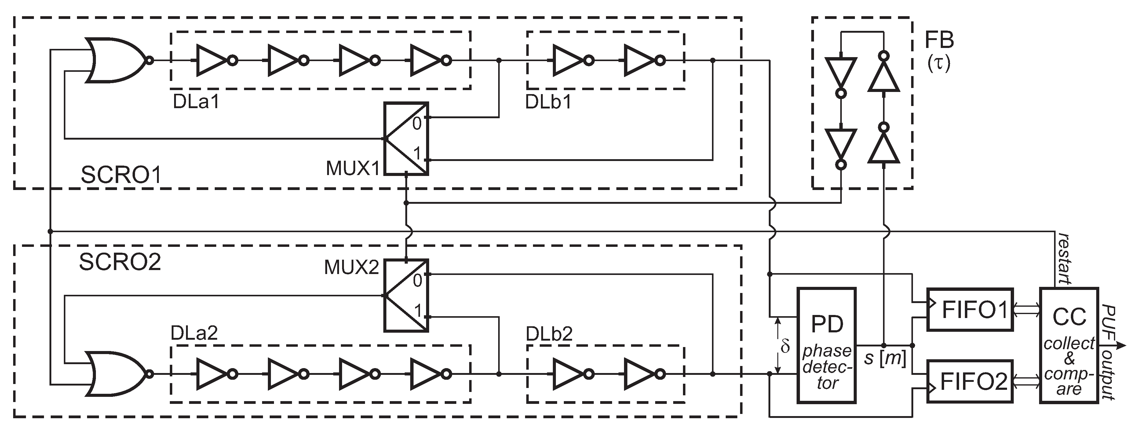
In order to tackle the described issues and join the advantages of analog chaotic signals with digital simplicity, it would be very valuable to identify an analog continuous variable that could be utilized in purely digital circuits. Therefore, we propose a concept of system with a continuous time variable () that manifests chaotic behavior. For this purpose, we base our PUF on recently introduced concept [45] with switchable chain ring oscillators (SCROs)—the idea incorporates a pair of SCROs (SCRO1 and SCRO2) as shown in Figure 1.
An SCRO consists of two switchable delay lines formed of inverters (DLa and DLb) and it operates at one of two frequencies (, ) that are never equal:
where and delays correspond to the DLa and DLb propagation times. Rising slopes at SCRO outputs are detected by a phase detector (PD), which acts as an arbiter providing logical when the rising slope of SCRO1 appears before SCRO2 ( for the m-th comparison). The logical occurs in the other case (). The simplest PD implementation consists of one D-flip-flop.
The feedback signal from the PD instantly aims to adjust SCRO phase () but never succeeds. Moreover, the feedback always comes a little late due to delays () of the feedback loop (FB). The higher feedback delay results in the greater range of possible SCROs phases. If was negligible, the circuit would operate in a periodic mode:
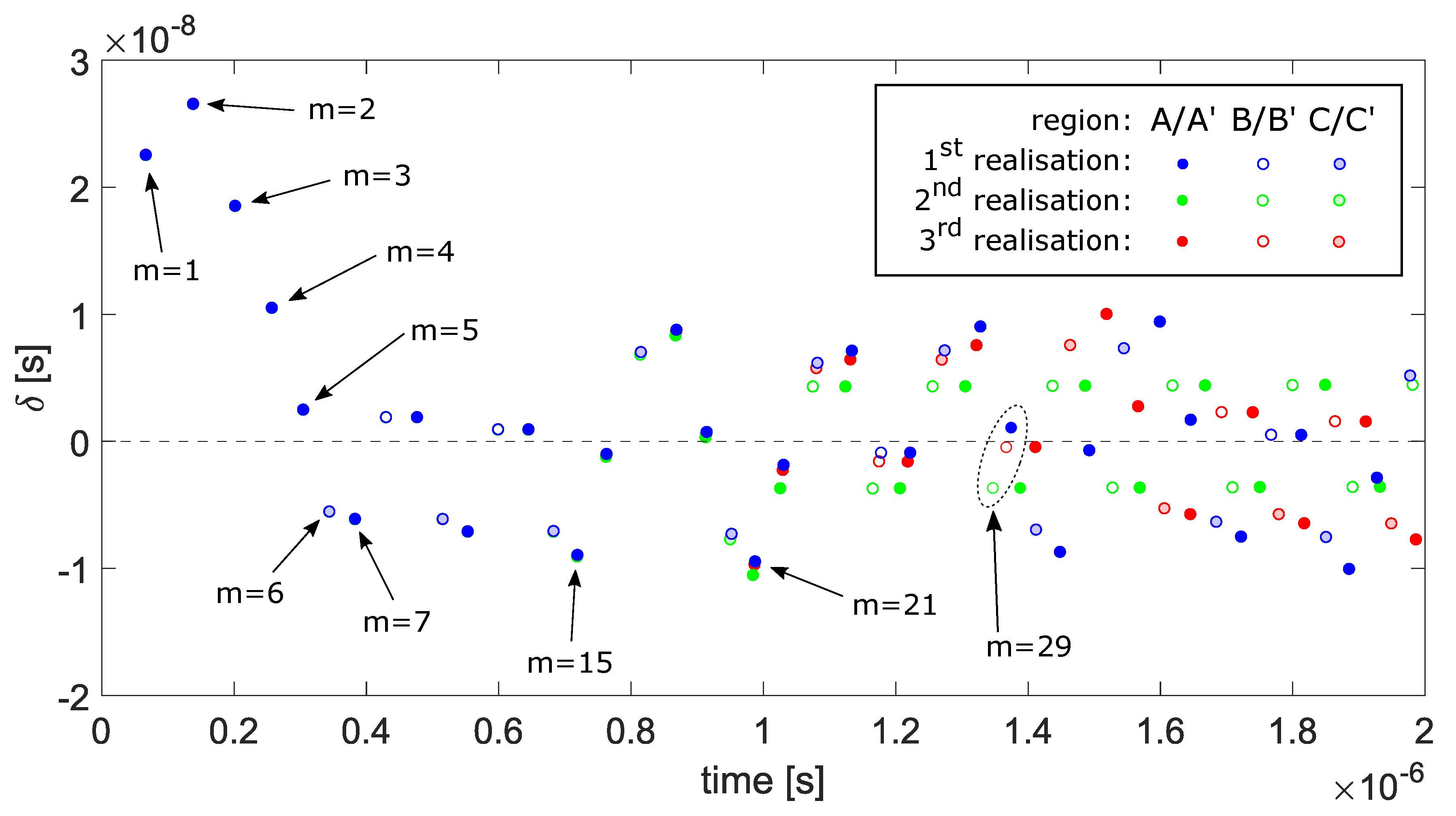
but, if the delay exceeds (i.e., ), the phase correction signal (the slope of a logical value change) for the higher frequency SCRO will not arrive on time (both SCROs will work on the same frequency for a moment). Moreover, if the delay exceeds the phase correction appears too late also for the other SCRO (the one operating at lower frequency) and there will be no phase correction on time. An example series of corrections for consecutive m steps () obtained in the Xilinx CoolRunner II (XC2C256) (San Jose, CA, USA) is shown in Figure 2.
Three realizations start from the same state (phase) and a wrong phase correction value (). They properly correct their phases in the next four steps ( 2, 3, 4, 5). Steps 6 and 7 (8 and 9; 10 and 11, etc.) show the case where the phase correction came too late for one of the SCROs.
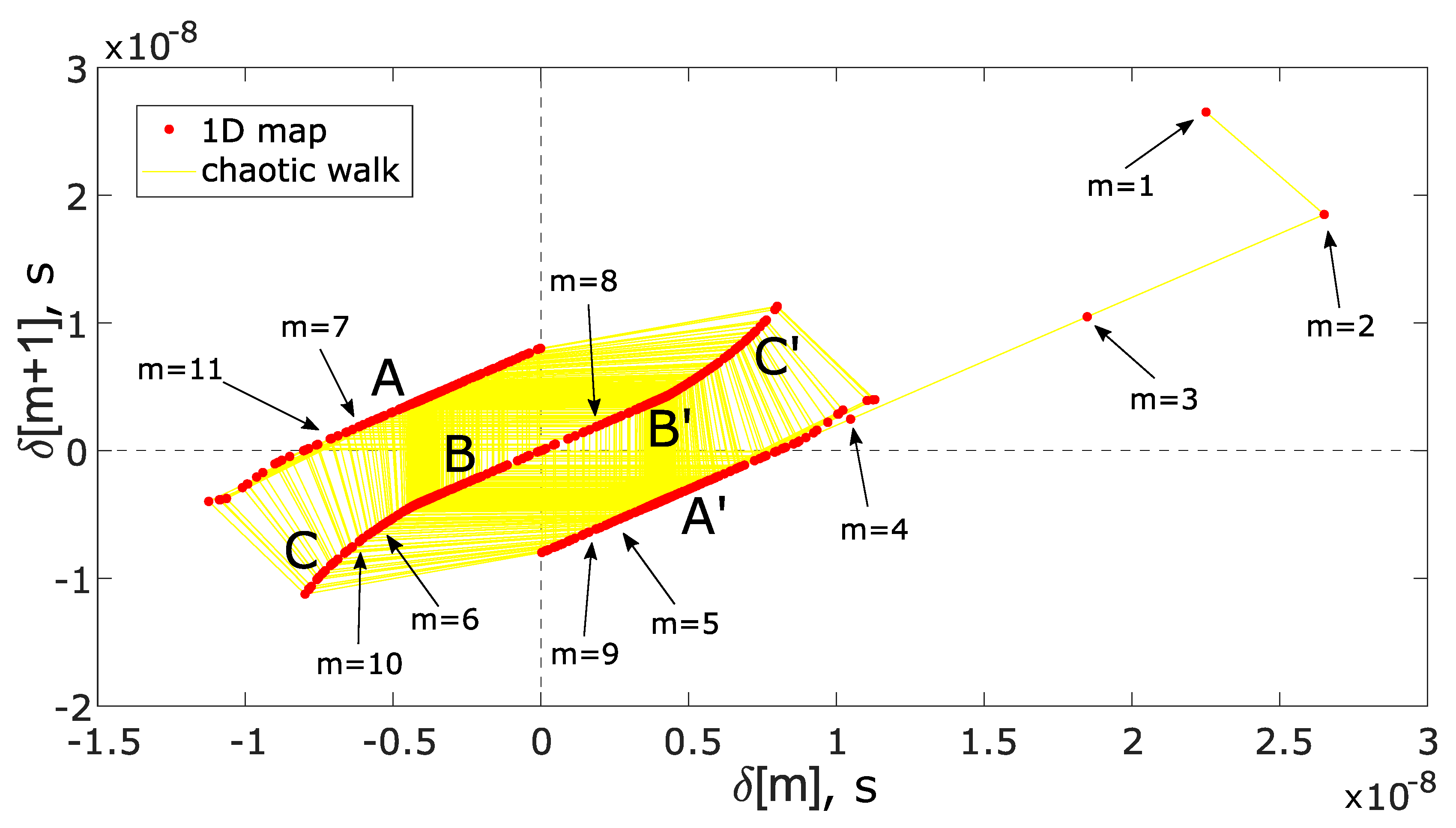
Usually, a chaotic 1D map is the easiest way to visualize chaotic behavior [46]; therefore, Figure 3 shows a graph of consecutive m steps.
One can see that there are three types of regions (A, B, C) associated with the circuit’s behavior depending on and complementary regions (, , ) since the phase adjustments are identical for the both positive and negative values. The standard regions of operation (A and ) can be understood as proper adjustments (as if there was no influence of delay). Regions B and correspond to the case when the adjustment in two subsequent steps does not apply (mainly due to the delay). The classification of the steps to the regions was also marked in Figure 2.
There is an important phenomenon that accelerates divergence of a system’s chaotic trajectory—mainly inconsistency of a logical level at multiplexer’s inputs (MUX1 or MUX2).
If the switching of an SCRO occurs at one of the slopes, it may cause a voltage discontinuity at the MUX output. This glitch, after it propagates through a number of inverters, causes a slight shift of the rising edge in one of SCROs, in which the inconsistency occurred. These states’ inconsistencies can be observed as extensions of linear B and regions and were marked as C and in Figure 3 (as well as in Figure 2). Another phenomenon occurs when the rising edges of SCROs are close enough to each other (). In this case, the PD classification result (of SCRO slope priority) may come a little late due to occurrences of metastability [15]. Such events are quite rare (but possible); nevertheless, they also influence the delay of the feedback correction signal (see [45]). In very rare cases of , the PD classification result (s) can be even wrong (a random value, due to metastability occurrence).
Such a chaotic system is very sensitive to tolerances of parameters of all electronic devices used in the design. Its sensitivity originates from all the physical parameters affected by process variations (transistors and paths geometry, material heterogeneity and as a result the electrical parameters). For this reason, any change in the circuit’s structure (e.g., the use of a different inverter or different path connecting the same elements) influences its behavior—it also opens the door to creation of various challenge vectors (in the PUF’s challenge–response system). It is also the reason why every instance of an identical circuit (having exactly the same placement and routing) behaves in a different way. One can see in the example in Figure 2 that, after several steps ( 15–20), the circuit’s trajectory starts different paths and, beginning from , the PD classifications also differ. This step () is a specific turning point for this particular implementation (particular structure). If the change in the circuit’s structure (for the sake of PUF’s challenge) is not an option, the paths or inverters can be easily multiplexed—for example, in the way it is implemented in BR-PUFs [33].
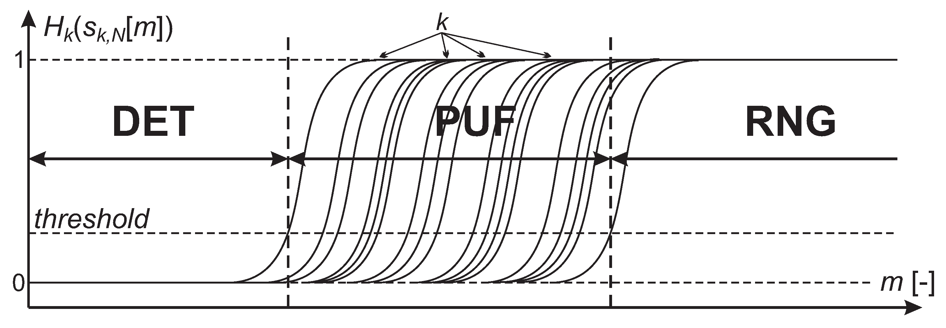
Since the SCROs can be considered as free running ring oscillators, there is obviously a phase walk present. At some point, it becomes to influence the circuit’s behavior resulting in circuit’s random state trajectory (as utilized in [45] for the use of true random number generator). If there was no phase walk (and other stochastic physical processes), the circuit would be a perfect deterministic chaotic system (with only the “initial conditions” determining its further behavior). However, after a period of time (a number of m steps, corresponding to m PD classifications), the circuit turns into a random number generator (RNG). Nevertheless, before it happens, and, after instance’s trajectory begins to differ, there is a time window for a PUF extraction as moments of randomness initialization—depicted in Figure 4.
Multiple runs () of the same instances () of the circuit in Figure 1 result in the same behavior till the moment when the stochastic physical processes start to randomize subsequent chaotic trajectories. It can be easily measured and observed by entropy values obtained from various realizations of (e.g., ) for adjacent steps () within one of instances. For example, if the output produced by one instance (k) at a specific step (m) for each of the (N) realizations is the same (either 1 or 0), then . On the other hand, if the half of the realizations at this step have different output values than the other half, then . When is reached, only a single bit out of nine has a different value (specifically ). Following the definition of Shannon’s entropy [47], the order of ones and zeros does not matter. This way, three different ranges of operation can be distinguished depending on the values of H. The first manifests the deterministic behavior for all instances (DET in Figure 4). The second range manifests different moments (for different instances) for the circuit to operate in the non-deterministic way (PUF key extraction). In the third range all of the instances manifest random behavior (RNG—random number generator).
3. Behavioral Modeling
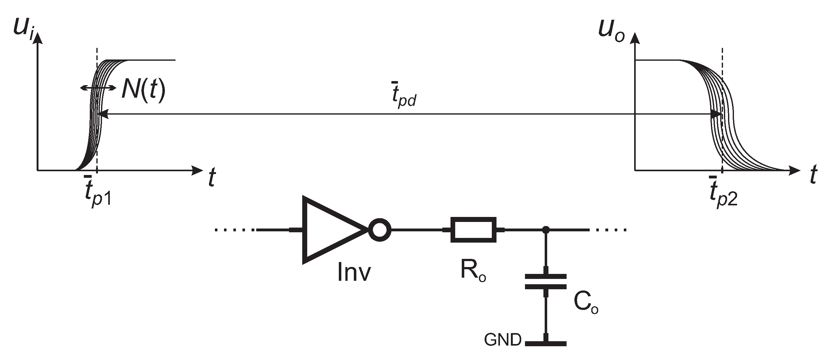
The chaotic circuit described with a 1D map must have a region of operation, in which the inclination coefficient of subsequent values of the state variable is , where and k, q are the constants which depend on the circuit parameters. The circuit shown in Figure 1 reveals a chaotic behavior due to the presence of C and regions with , as shown in Figure 3. These regions of operation result from the delay in the feedback loop (FB), which causes the logical state inconsistency in C and ranges of operation. In order to extensively verify the chaotic behavior of the system proposed in Figure 1, we have implemented its behavioral model in a Matlab Simulink environment (Matlab R2017a, The MathWorks, Inc., Natick, MA, USA). In the model, we have assumed linear and lumped output inverter resistance and input capacitance (of adjacent inverter attached in the ring), as shown in Figure 5.
These two lumped components are responsible for the finite rising/falling edges of signals. Subsequently, we have assumed the sigmoid transfer function (hyperbolic tangent) of direct current inverter characteristics, constant signal delay , and a Gaussian noise process affecting the threshold level of the inverter (its transfer function). The process of our model represents the phase walk of SCROs in their physical implementation, and allowed us to obtain non-deterministic circuit behavior, available in the physical implementations either in FPGA or CPLD. All the parameters , , , (standard deviation) and inclination of the transfer function have been adjusted to obtain identical operation of SCROs in the Simulink model and physical implementation. The detailed method of parameter extraction is explained in [48]. This way, we have obtained identical phase-walk (and jitter), and frequencies of the model and the circuit physically implemented in a programmable device. With the use of the Simulink, we simulated the chaotic behavior of the circuit proposed in Figure 1. For this reason, we performed multiple transient analysis, in which the DLa1, DLb1, DLa2, DLb2, FB parameters (i.e., and , ) were subjected to 1% dispersion (Monte Carlo analysis). During the analysis, the series of values were registered for subsequent K sets of randomly generated DLa1, DLb1, DLa2, DLb2, FB parameters. Each transient analysis for a particular parameter set was repeated N times (realizations) in order to observe the non-deterministic circuit behavior of a particular parameter set. The experiment scheme can be described according to formula (3):
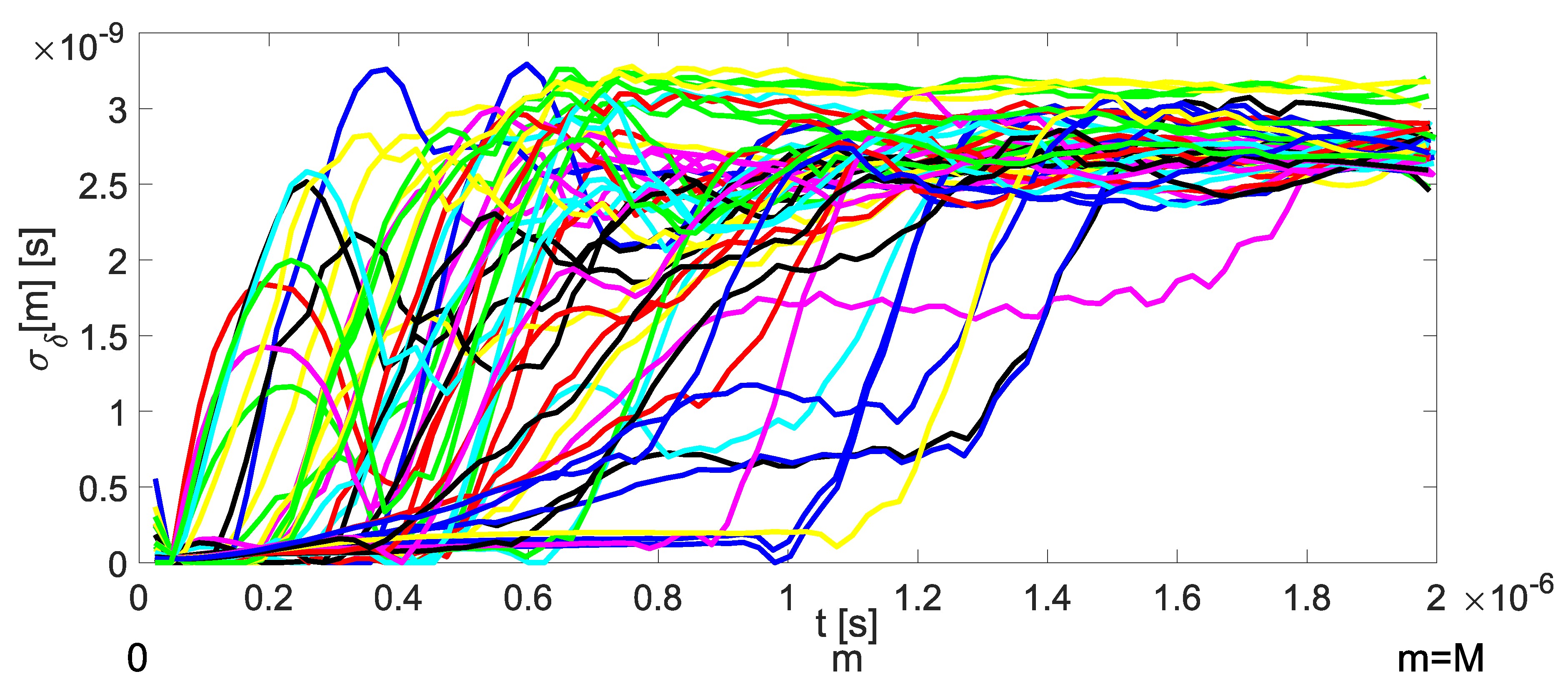
This way, we obtained bit-strings of variable series sets and analyzed the standard deviations of the , , ..., sets. After that, we were able to analyze the fluctuations of standard deviation in time , depending on the inter-class tolerance of circuit parameters. Figure 6 shows the standard deviation as a function of time (and ) for particular instances ().
One can see that the standard deviation of rapidly rises at a certain moment of time ; however, the moment of rapid increase depends on the particular system’s parameter set (tolerance). The simulation results in Figure 6 clearly show that the time or the number of PD classifications is a variable that distinguishes instances of the circuit, whereas this particular moment divides the chaotic operation of the circuit in Figure 1 to either deterministic or non-deterministic operation.
Results in Figure 6 show the random behavior of the circuit’s state variable .
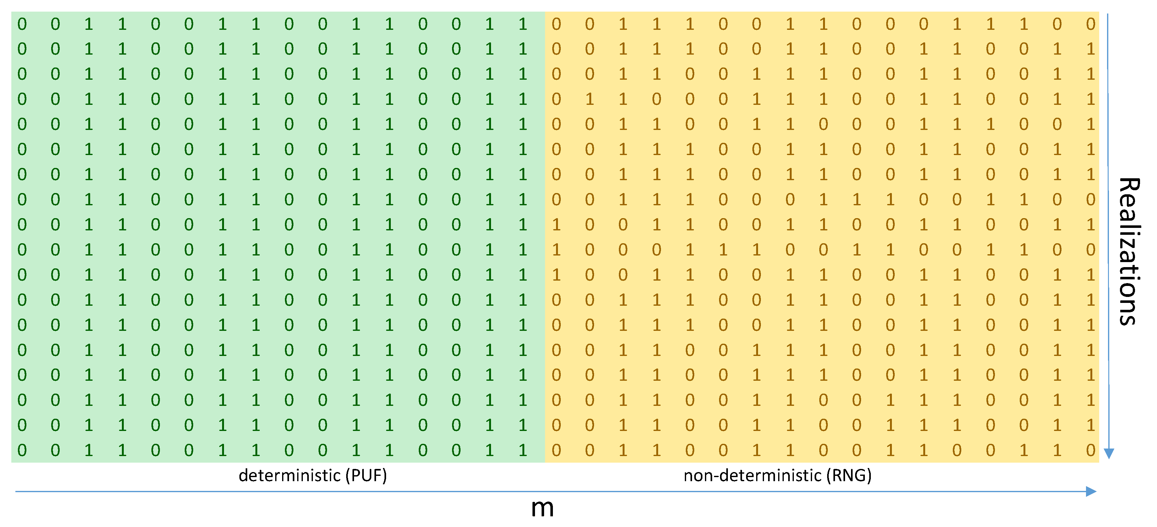
The proposed chaotic circuit is asynchronous; therefore, is a continuous variable. In order to easily determine the moment of the abrupt change of the circuit’s mode of operation (i.e., from deterministic to non-deterministic), it would be much easier to assess its mode according to the bit-string produced at the output of the PD block (see Figure 1). It is obvious that, when starts to act as a random variable, the PD circuit produces a random bit-string. An example of such a PD operation obtained in Simulink for a single instance is shown in Figure 7.
One can see that the PD bit-string generated in multiple realizations (within a single instance) can be divided into two regions, the first, in which each m-th element is independent from the realization, and the second, where the m-th bit-string element depends on the realization number (circuit run). In the first case, the Shanon entropy (calculated vertically) is approximately 0, whereas the second case yields Shannon entropy close to 1. Example results in Figure 7 show that the iteration number that distinguishes the deterministic from non-deterministic operation could act as a PUF response.
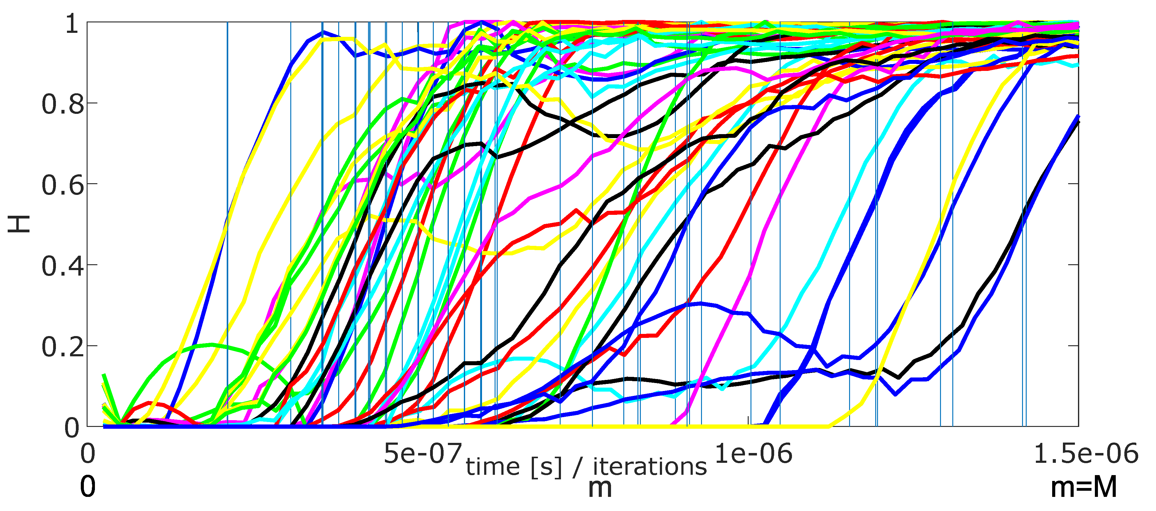
A complete simulation according to (3) has been performed, whereas the Shannon entropy of bit-strings (see Figure 7) was used to determine the critical m iteration number (PUF response). The results of Monte Carlo simulation (with a use of a Savitzky–Golay filter due to sudden changes in values) are shown in Figure 8. The vertical lines indicate the moments dividing the deterministic from non-deterministic chaotic operations.
The results in Figure 8 clearly show that, for an arbitrarily chosen H threshold (e.g., ), the m value dividing types of operation acts as a PUF response (e.g., ). During simulations in Simulink, we have obtained critical m values ranging from 16 to 53, which yields 5.2 bits of a single PUF response.
We have also checked the temperature impact on the modeled device. For this purpose, the propagation delay of all modeled inverters and their jitter were subjected to temperature influence. Both the propagation delay and noise of inverters result from the physical phenomena typical for CMOS technology; however, in the case of jitter modeling of ring oscillators formed of inverters, it is hard to distinguish the influence of thermal Gaussian noise from the shot noise. For this reason, we have measured the inverter noise parameters by the measurement of jitter of physically implemented ring oscillators (in FPGA) in various temperatures (stabilized with a Peltier module). This way, we obtained the standard deviation of noise process for various temperatures in different devices (FPGA). The method was explained in details in [48]; moreover, it was also utilized for the measurements of thermal drift of average propagation delay, not resulting from the noise processes. Both the noise standard deviation and propagation delay thermal coefficients were used in the behavioral modeling (in Simulink), in order to evaluate the temperature impact on the critical m-value. We performed the Monte Carlo analysis of the circuit shown in Figure 1 with the experiment scheme (3) in 260 K. Furthermore, we repeated the experiment with the same set of randomly distributed tolerances of instances at 300 K. This way, we obtained two sets of critical m values, i.e., and . The T-test (ttest2 in Matlab environment) applied to m variables from and corresponding to the same instances revealed that they fall into distributions with slightly different mean values. It turned out that a 40 K change in temperature results in change in mean value of obtained m for the same instances. Therefore, the simulation yields critical m sensitivity (and therefore PUF sensitivity) to temperature.
4. Testing and Results
The preliminary verification was based on the implementations in five Xilinx Cool-Runner II CPLDs (three XC2C256 devices and two XC2C64) as well as nine devices of Xilinx Artix-7 XC7A100T FPGAs (CSG324ABX1625/1629). The bit-strings were acquired with the use of the Texas Instruments DK-TM4C123G board (Dallas, TX, USA) connected to the PUF output as well as PD output signals were observed and measured with both oscilloscope and Agilent 53230A timer (currently Keysight, Santa Rosa, CA, USA). We have evaluated series of circuit’s architectures by changing the numbers of inverters (implemented as look-up tables—LUTs) in each type of delay lines (DLa, DLb, FB). Consequently, we have selected for the following research the architecture that consists of: 13 LUTs in the DLa (DLa1, DLa2), six LUTs in the DLb (DLb1, DLb2) and nine LUTs in the FB (as ). It is worth mentioning that the circuit’s architecture, which can be seen just as numbers of standard delays in each of the chains (DLa, DLb, FB), is perfectly scalable and can be used in various devices made in various technology processes. For that reason, we have chosen for tests two quite faraway models of devices: 0.18 m CPLDs and 28 nm FPGAs.
Every circuit was initiated with eight different PUF challenges (eight different SCRO elements placement or routing) and the implementations were exactly copied to each of instances (). The number of steps, after which the entropy () abruptly increases, was estimated as a distance between the system initialization and the moment when (see Figure 4). The distance, measured as a number of consecutive comparisons was used as a PUF response. Analysis of five CPLDs and nine FPGAs indicated a linear correlation between challenges and responses within one device (intra-class correlation). On the other hand, the same implementations in different devices showed a uniqueness of each device (lack of inter-class correlation).
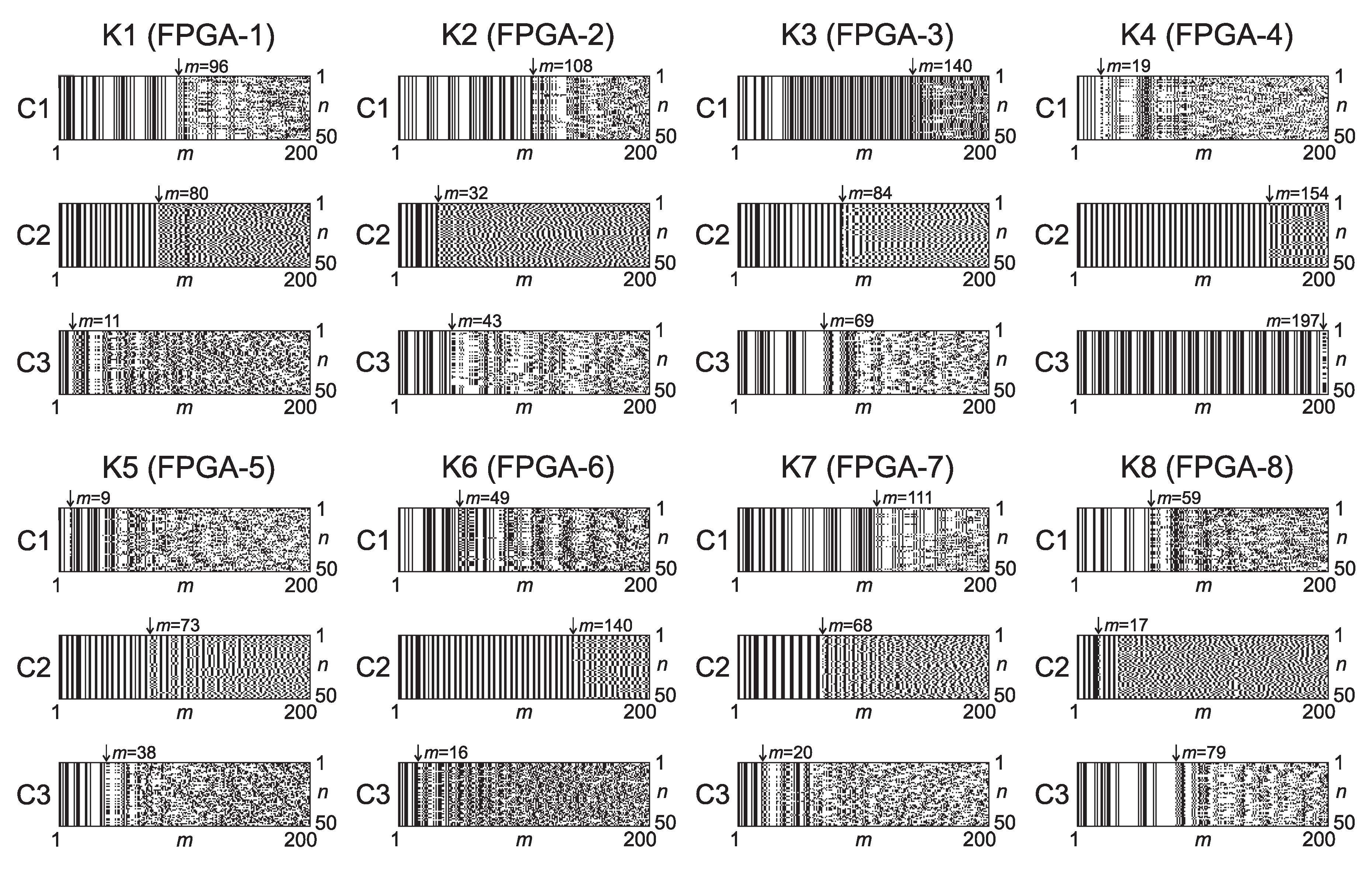
Figure 9 demonstrates a few examples of PD output bit-strings () in a form of binary bitmaps—50 runs (n) of 200 steps (m) for eight example FPGA instances (K1–K8) and three challenges (C1, C2, C3). Derived keys are basically the numbers of steps (m) after which the deterministic chaos ends and the non-deterministic chaos begins. In the tests, the PUF time window (depicted in Figure 4) began at the value and ended with (therefore the observation window was shortened to steps). Such a range (in binary representation) results in 7,6 bits of a key. The dispersion of the moment when H leads effectively to ∼6–7 bits of entropy with just a single challenge. The difference in the PUF time window between simulations and the physical implementations likely involves two factors. First, the model did not result from the actual technological spread that occurred at manufacture of devices. Second, the research involved only several devices—we cannot conclude about PUF statistical occurrences nor keys randomness based on such a small number of instances. For that reason, future research should follow.
Taking into consideration practical aspects of retrieving PUF keys from a single instance, it is apparent that multiple bit-strings are required, but both the number of the streams as well as the required length of the stream vary. Since the 0.5 Shannon’s entropy level is not very demanding in terms of variance or Hamming distance (the half value of H is reached when only one of nine bits differs), basically the first different bit-string can indicate the beginning of non-deterministic chaotic operation—as a matter of fact, the first different value between the bit-strings. After the first difference occurs, the remaining part of the bit-string is redundant (nevertheless, it should be generated because of the vulnerability to timing SCAs). Consequently, the minimum number of bit-strings is two, whereas the maximum results from acceptable entropy uncertainty, and as a consequence, the acceptable critical m fluctuations. For this reason, we suggest to either generate a fixed number of bit-strings (e.g., ) or to stop when the first bit-string differs from the others. In each of the procedures, there is always a possibility that a rare event for lower m may cause disturbance resulting in an incorrect m value. The error can be avoided by increasing the number of bit-strings, but it may be more efficient to ignore the result (detect the error with a simple cyclic redundancy check code) and repeat the key generation procedure. The number of bit-strings required to generate the m values for all of the examples presented in Figure 9 varies from 2 to 6—on average, 3.04 bit-strings per one generation.
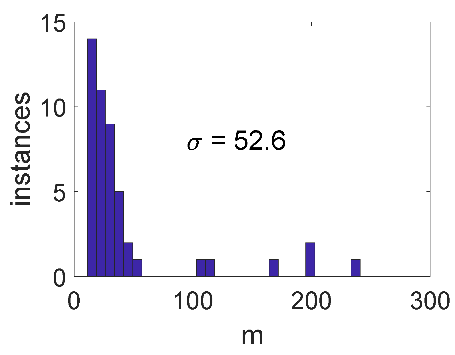
In order to evaluate limitations of the proposed solution, we estimated critical m-values for eight Artix (Xilinx) and eight Cyclone 5 (Altera/Intel (Santa Clara, CA, USA)) devices, where each consisted of three independent PUFs. This way, we were able to estimate a histogram of critical m-values (keys), shown in Figure 10. The measured inter-class randomness of PUF estimated with standard deviation was . Despite the limited probe size (16 devices × 3 PUFs), one can see in Figure 10 that the m distribution is asymmetric and the most likely m values are located in the 10–50 range (obtained also in simulation). The asymmetric m distribution results strictly from the influence of noise on the trajectory of chaotic system. In such a system, the location of subsequent points (see Figure 3) is strongly affected by the slight phase fluctuations (resulting from noise processes) during subsequent system states. In other words, the longer circuit operates, the higher the number of transitions near C and is. Therefore, it is unlikely to maintain the same deterministic behavior for high m-values in subsequent realizations by the system.
In the proposed PUF solution, the chaotic operation results from C and ranges of operation, which ensure inclination in the chaotic map. The tolerances present in the system affect both the inclination of C and ranges (sections of chaotic map) and the length of these sections. Therefore, tolerances affect the probability of entering C and ranges of operation, and, in turn, the probability of entering different (random) trajectory paths.
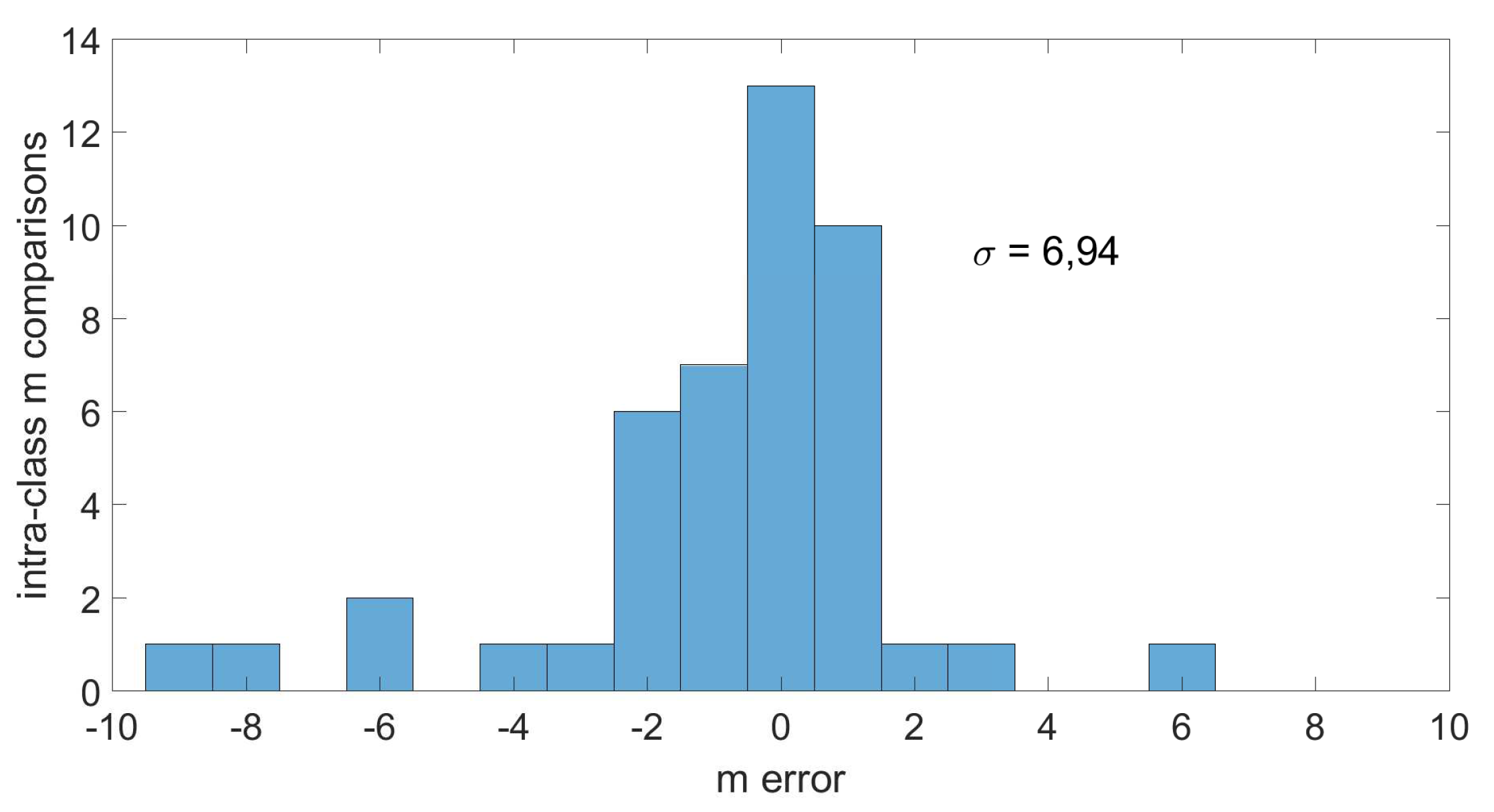
The other parameter vital to PUFs is its reliability, which identifies the intra-class randomness. The 48 PUF instances used for randomness extraction in Figure 10 were subjected to challenge–response operation multiple times in the same operating conditions. This way, the m error distribution was obtained, which is shown in Figure 11. The mean value of obtained distribution , whereas the standard deviation . It is worth mentioning that m error mainly results from the non-monotonic character of dependence (see Figure 8), which affects the estimate of critical m-value based on the threshold level. Nevertheless, over 80% of intra-class m error corresponds to 2-bit Hamming distance, whereas the maximum Hamming distance corresponds to 3-bits.
We have also investigated the influence of temperature on the critical m-value. For this purpose, 100 realizations (runs), of steps long each (within each PUF instance) were used to estimate dependence for two operating temperatures (i.e., 260 K and 300 K). Each PUF response requires multiple runs (realizations n) of chaotic system iterations . Therefore, each PUF response requires iterations, where each m’th iteration length results from the corresponding SCRO frequency (1). It is obvious that each PUF response requires a interval; therefore, when 400 MHz average frequency of FPGAs is assumed, a single PUF response requires at least 25 s without post-processing (e.g., entropy calculation).
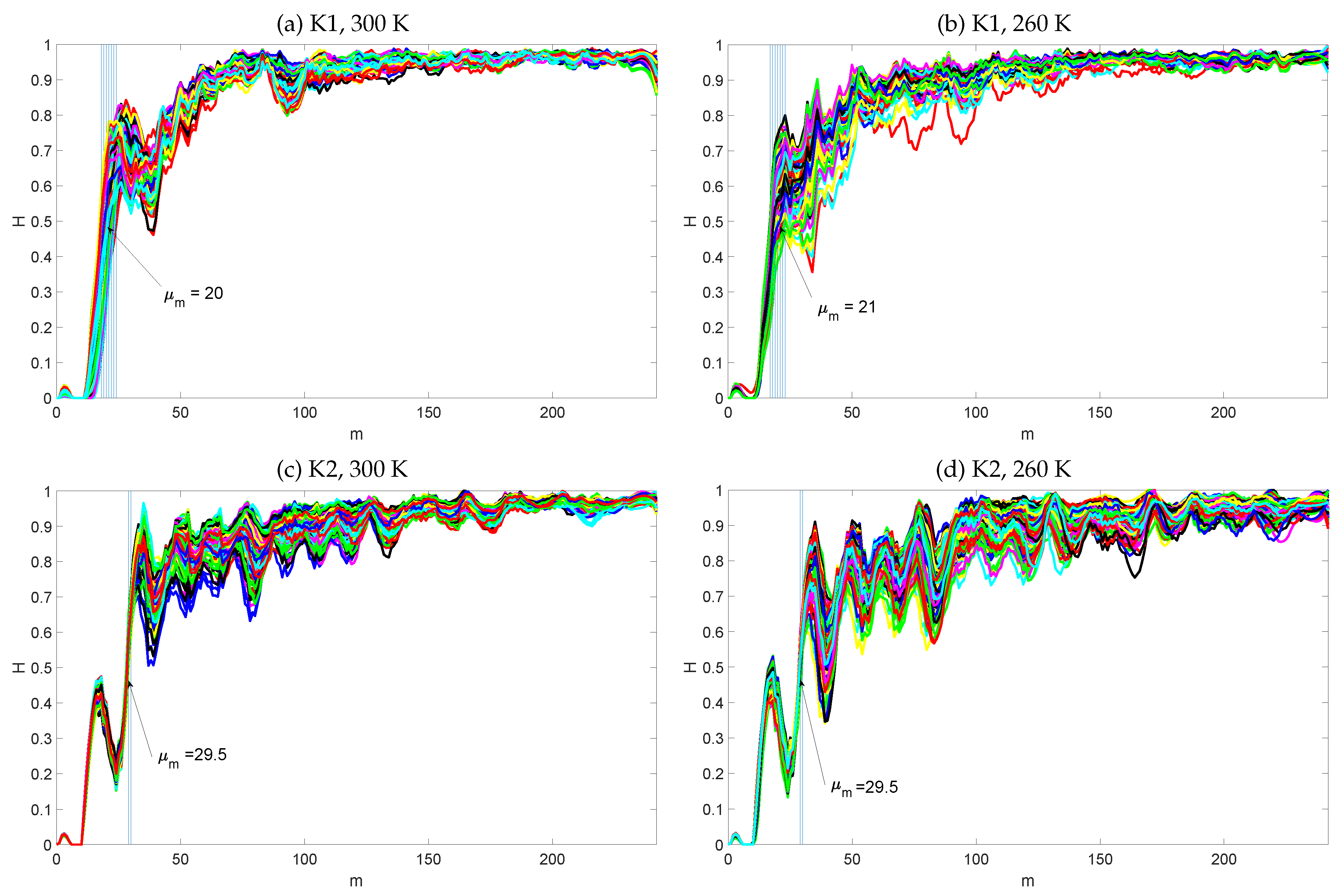
Each 25 s experiment (single PUF response extraction) was repeated multiple times in hardware (FPGA), in order to verify the PUF stability and reliability. The example results for two FPGA instances at 260 K and 300 K are shown in Figure 12. One can see that, despite the temperature change, the critical m-value (PUF response) is rather invariant over temperature (Figure 12a–d). It turns out that the temperature mainly affects the amplitude of local H fluctuations; however, the global moment of rapid entropy increase remains constant in a particular device. The results in Figure 12 show the temperature influence on the dependence, whereas, to evaluate the temperature impact on multiple instances, we needed to extract critical m-values (PUF responses) from multiple PUFs implemented in eight Artix and eight Cyclone V devices in 300 K and 260 K, respectively.
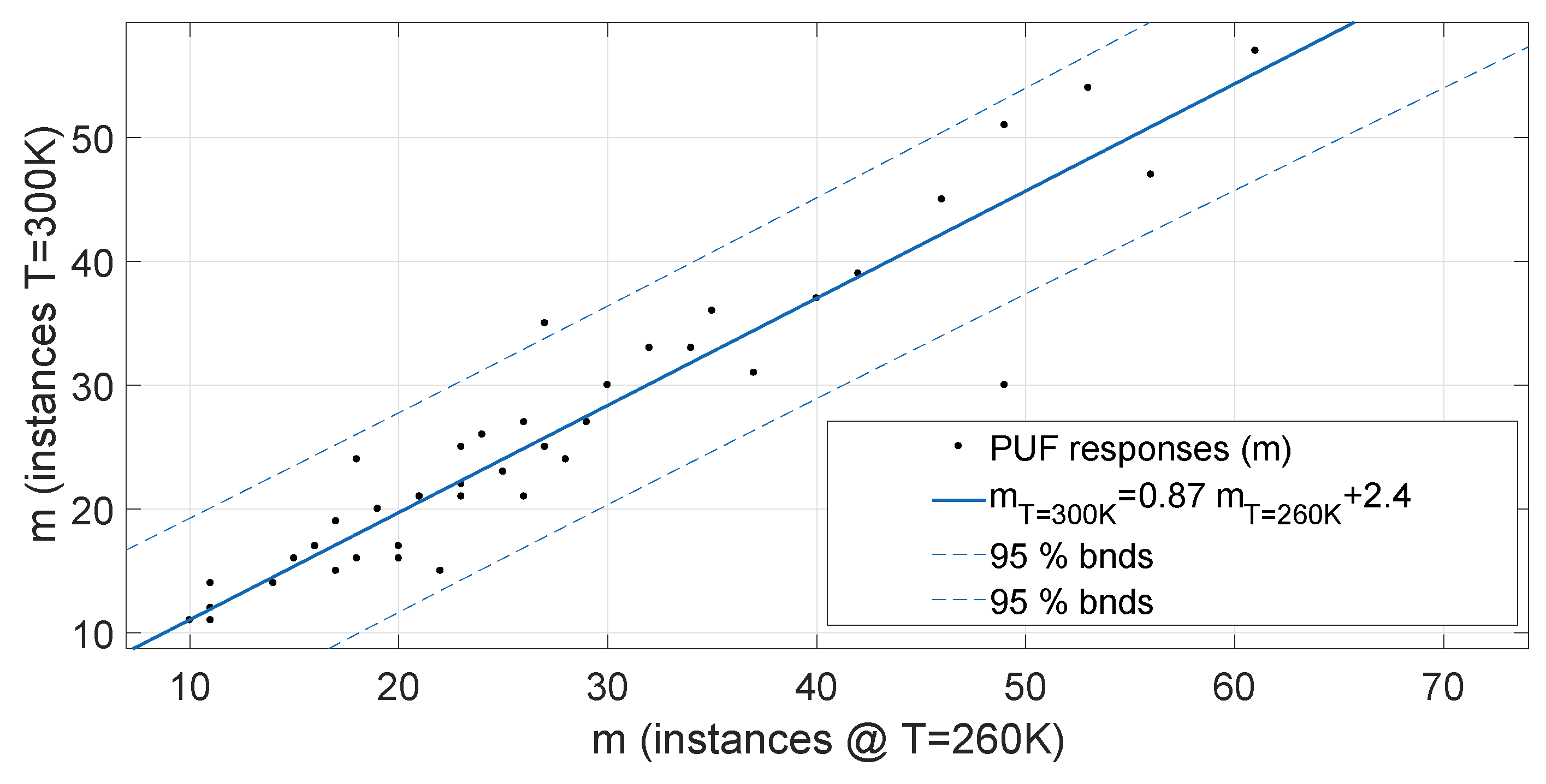
The PUF responses () corresponding to particular instances were used to build a regression plot in Figure 13. One can see that PUF responses can be easily approximated with a linear function. The inclination coefficient (0.87) in Figure 13 proves that PUF responses in higher temperature (300 K) are slightly shorter (smaller) than in the case of lower temperature (260 K). These results are in accordance with Monte Carlo analysis discussed in Section 3.
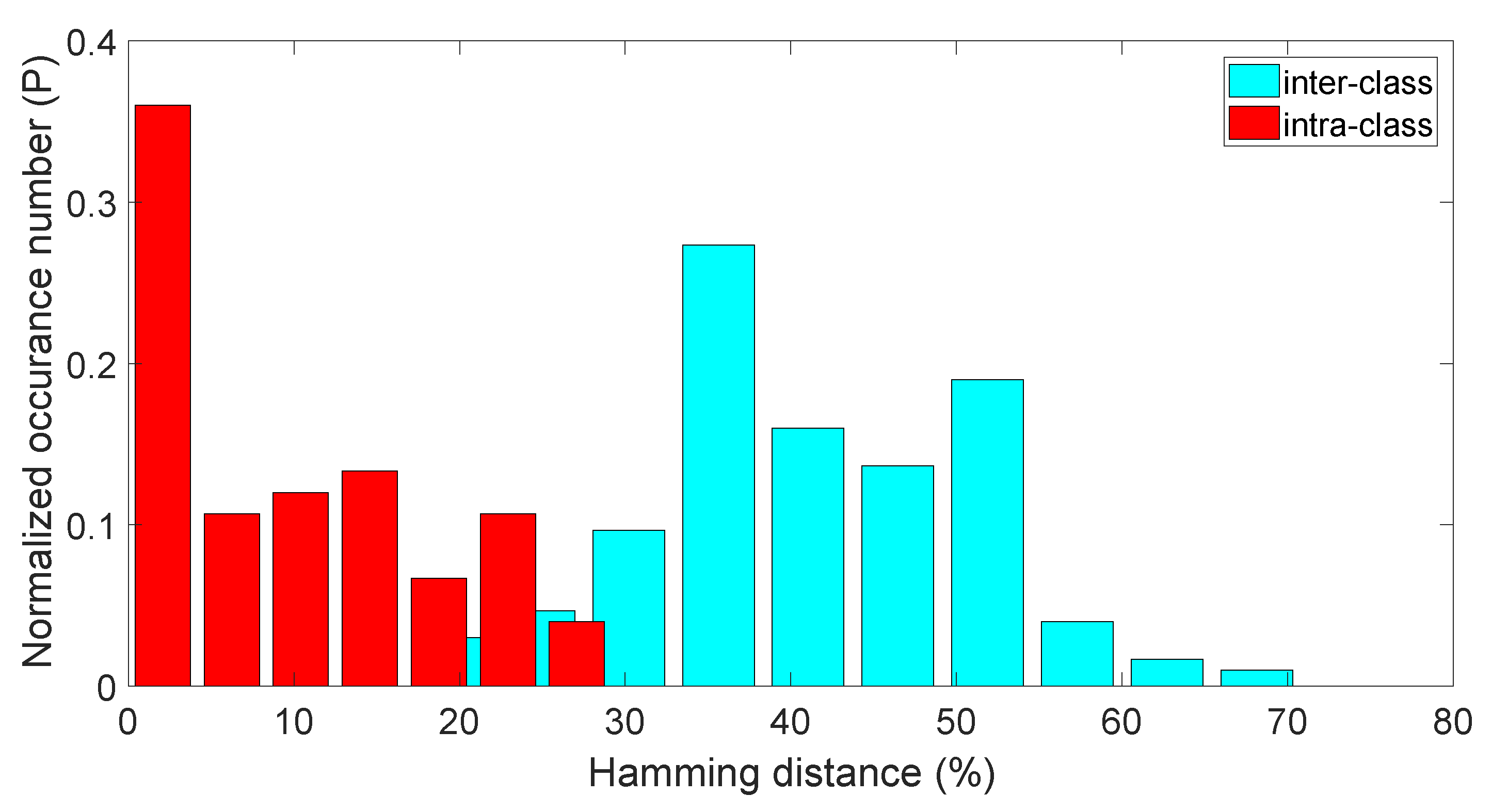
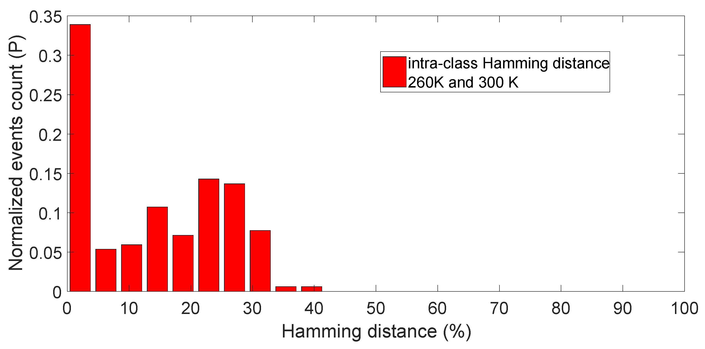
In order to evaluate the PUF performance using common metrics (see, for example, [7,49]), we have combined three m-values (each represented by 8 bits) into one 24-bit PUF key. The differences between such keys (bit sequences) were measured with the use of Hamming distance—the number of different bits between two keys. Figure 14 shows normalized probability of occurrence of particular Hamming distances between keys in percentages for both inter-class (keys compared between different chips) and intra-class (keys repeatedly sampled within the same chip) distributions. The influence of the temperature change on such keys can be observed in Figure 15. Based on these results (and following common PUF metrics [7,49]), we were able to estimate the basic PUF keys parameters:
Uniqueness: 41.16%,
Reliability: 91.33%,
Uniformity: 36.50%.
It is worthwhile to mention that such a chaotic circuit amplifies microscopic differences between instances in the way that even the device manufacturer cannot predict the results. Moreover, since every change in the implementation results in different keys, the number of PUF challenges within even a simple device strives for infinity. An invasive attempt to measure transistors and paths geometry, material heterogeneity as well as many other device parameters most likely would change the unique trajectory and destroy the keys. On the other hand, even if someone had succeeded, it would have been impossible to reconstruct an instance or to create simulation model that would have resulted in exactly the same chaotic trajectory and the same cryptographic keys.
5. Conclusions
The paper introduced an novel idea of generating unique PUF/POK cryptographic keys being derived from a chaotic circuit implemented in programmable devices. A new design of a chaotic circuit was also adapted—it utilizes time as an analog continuous state variable, which is very uncommon in purely digital systems, and as a result joins the advantages of analog chaotic signals with digital simplicity of implementation. The PUF keys were derived from the length of the deterministic part of a circuit’s chaotic behavior. Both the simulations and physical measurements proved that the chaos theory should be explored for the sake of PUFs as a natural mechanism of amplifying random process variations of digital circuits (simple as well as advanced). The design was successfully tested in cheap CPLDs as well as in state-of-the-art FPGAs. The results showed significantly different keys derived from different instances programmed with precisely the same bit-stream as well as from slightly different implementations within one instance. The solution fits into the modern trends of developing highly secured hardware resistant to side-channel attacks, but not expensive and with universal application at the same time.
6. Patents
The presented solution is a patent pending technology. On 7 August 2018, an international patent application was filled under number PCT/IB2018/055943 based on three Polish patent applications (PL422486, PL422487 and PL425581 filed in the Polish patent office) with the earliest claimed priority date of 8 August 2017. The patent was internationally published by the World Intellectual Property Organization on 14 February 2019 under the number WO 2019/030670.
Author Contributions
Conceptualization, K.G.; data curation, P.Z.W.; formal analysis, K.G. and P.Z.W.; funding acquisition, K.G. and P.Z.W.; investigation, P.Z.W.; methodology, K.G.; project administration, K.G.; resources, K.G. and P.Z.W.; software, P.Z.W.; supervision, K.G.; validation, P.Z.W.; visualization, K.G. and P.Z.W.; writing—original draft, K.G. and P.Z.W.; writing—review & editing, K.G. and P.Z.W.
Funding
This research received no external funding.
Conflicts of Interest
The authors declare no conflict of interest.
Abbreviations
The following abbreviations are used in this manuscript:
Skorobogatov, S.P. Semi-Invasive Attacks: A New Approach to Hardware Security Analysis; Technical report, UCAM-CL-TR-630; University of Cambridge: Cambridge, UK, 2005. [Google Scholar]
Torrance, R.; James, D. The State-of-the-Art in IC Reverse Engineering. In Cryptographic Hardware and Embedded Systems—CHES 2009; Clavier, C., Gaj, K., Eds.; Springer: Berlin/Heidelberg, Germany, 2009; pp. 363–381. [Google Scholar]
Xie, Y.; Xue, X.; Yang, J.; Lin, Y.; Zou, Q.; Huang, R.; Wu, J. A Logic Resistive Memory Chip for Embedded Key Storage with Physical Security. IEEE Trans. Circuits Syst. II Express Briefs2016, 63, 336–340. [Google Scholar] [CrossRef]
Aziz, B.; Arenas, A.; Crispo, B. Engineering Secure Internet of Things Systems; Institution of Engineering and Technology: London, UK, 2016. [Google Scholar]
Bayat-Sarmadi, S.; Kermani, M.M.; Azarderakhsh, R.; Lee, C.Y. Dual-Basis Superserial Multipliers for Secure Applications and Lightweight Cryptographic Architectures. IEEE Trans. Circuits Syst. II Express Briefs2014, 61, 125–129. [Google Scholar] [CrossRef]
Tanamoto, T.; Yasuda, S.; Takaya, S.; Fujita, S. Physically Unclonable Function Using an Initial Waveform of Ring Oscillators. IEEE Trans. Circuits Syst. II Express Briefs2017, 64, 827–831. [Google Scholar] [CrossRef]
Tanaka, Y.; Bian, S.; Hiromoto, M.; Sato, T. Coin Flipping PUF: A Novel PUF with Improved Resistance against Machine Learning Attacks. IEEE Trans. Circuits Syst. II Express Briefs2018, 65, 602–606. [Google Scholar] [CrossRef]
Barbareschi, M.; Natale, G.D.; Torres, L.; Mazzeo, A. A Ring Oscillator-Based Identification Mechanism Immune to Aging and External Working Conditions. IEEE Trans. Circuits Syst. I Regul. Pap.2018, 65, 700–711. [Google Scholar] [CrossRef]
Marchand, C.; Bossuet, L.; Mureddu, U.; Bochard, N.; Cherkaoui, A.; Fischer, V. Implementation and Characterization of a Physical Unclonable Function for IoT: A Case Study With the TERO-PUF. IEEE Trans. Comp. Aided Des. Integr. Circuits Syst.2018, 37, 97–109. [Google Scholar] [CrossRef]
Amsaad, F.; Niamat, M.; Dawoud, A.; Kose, S. Reliable Delay Based Algorithm to Boost PUF Security Against Modeling Attacks. Information2018, 9, 224. [Google Scholar] [CrossRef]
Kömürcü, G.; Pusane, A.E.; Dündar, G. Enhanced challenge-response set and secure usage scenarios for ordering-based ring oscillator-physical unclonable functions. IET Circuits Dev. Syst.2015, 9, 87–95. [Google Scholar] [CrossRef]
Liu, R.; Chen, P.Y.; Peng, X.; Yu, S. X-Point PUF: Exploiting Sneak Paths for a Strong Physical Unclonable Function Design. IEEE Trans. Circuits Syst. I Regul. Pap.2018, 65, 1–10. [Google Scholar] [CrossRef]
Kim, H.; Hong, S. AES Sbox GF(24) inversion functions based PUFs. In Proceedings of the International SoC Design Conference (ISOCC), Jeju, Korea, 3–6 November 2014; pp. 15–16. [Google Scholar]
Wieczorek, P.Z.; Golofit, K. Metastability occurrence based physical unclonable functions for FPGAs. Electron. Lett.2014, 50, 281–283. [Google Scholar] [CrossRef]
Vijayakumar, A.; Patil, V.C.; Kundu, S. On Improving Reliability of SRAM-Based Physically Unclonable Functions. J. Low Power Electron. Appl.2017, 7, 2. [Google Scholar] [CrossRef]
Gong, M.; Liu, H.; Min, R.; Liu, Z. Pitfall of the Strongest Cells in Static Random Access Memory Physical Unclonable Functions. Sensors2018, 18, 1776. [Google Scholar] [CrossRef] [PubMed]
Anagnostopoulos, N.A.; Katzenbeisser, S.; Chandy, J.; Tehranipoor, F. An Overview of DRAM-Based Security Primitives. Cryptography2018, 2, 7. [Google Scholar] [CrossRef]
Anagnostopoulos, N.A.; Arul, T.; Fan, Y.; Hatzfeld, C.; Schaller, A.; Xiong, W.; Jain, M.; Saleem, M.U.; Lotichius, J.; Gabmeyer, S.; et al. Intrinsic Run-Time Row Hammer PUFs: Leveraging the Row Hammer Effect for Run-Time Cryptography and Improved Security. Cryptography2018, 2, 13. [Google Scholar] [CrossRef]
Kumar, A.; Sahay, S.; Suri, M. Switching-Time Dependent PUF Using STT-MRAM. In Proceedings of the 31st International Conference on VLSI Design and 17th International Conference on Embedded Systems (VLSID), Pune, India, 8–10 January 2018; pp. 434–438. [Google Scholar] [CrossRef]
Chen, A. Reconfigurable physical unclonable function based on probabilistic switching of RRAM. Electron. Lett.2015, 51, 615–617. [Google Scholar] [CrossRef]
Kim, J.; Ahmed, T.; Nili, H.; Yang, J.; Jeong, D.S.; Beckett, P.; Sriram, S.; Ranasinghe, D.C.; Kavehei, O. A Physical Unclonable Function With Redox-Based Nanoionic Resistive Memory. IEEE Trans. Inf. Forensics Secur.2018, 13, 437–448. [Google Scholar] [CrossRef]
Schaller, A.; Xiong, W.; Anagnostopoulos, N.A.; Saleem, M.U.; Gabmeyer, S.; Skoric, B.; Katzenbeisser, S.; Szefer, J. Decay-Based DRAM PUFs in Commodity Devices. IEEE Trans. Dependable Secur. Comp.2018. [Google Scholar] [CrossRef]
Wang, W.C.; Yona, Y.; Diggavi, S.N.; Gupta, P. Design and Analysis of Stability-Guaranteed PUFs. IEEE Trans. Inf. Forensics Secur.2018, 13, 978–992. [Google Scholar] [CrossRef]
Sahoo, D.P.; Mukhopadhyay, D.; Chakraborty, R.S.; Nguyen, P.H. A Multiplexer-Based Arbiter PUF Composition with Enhanced Reliability and Security. IEEE Trans. Comp.2018, 67, 403–417. [Google Scholar] [CrossRef]
Cao, Y.; Zhang, L.; Zalivaka, S.S.; Chang, C.H.; Chen, S. CMOS Image Sensor Based Physical Unclonable Function for Coherent Sensor-Level Authentication. IEEE Trans. Circuits Syst. I Regul. Pap.2015, 62, 2629–2640. [Google Scholar] [CrossRef]
Herkle, A.; Becker, J.; Ortmanns, M. Exploiting Weak PUFs From Data Converter Nonlinearity—E.g., A Multibit CT ΔΣ Modulator. IEEE Trans. Circuits Syst. I Regul. Pap.2016, 63, 994–1004. [Google Scholar] [CrossRef]
Wan, M.; He, Z.; Han, S.; Dai, K.; Zou, X. An Invasive-Attack-Resistant PUF Based On Switched-Capacitor Circuit. IEEE Trans. Circuits Syst. I Regul. Pap.2015, 62, 2024–2034. [Google Scholar] [CrossRef]
Guo, Y.; Dee, T.; Tyagi, A. Barrel Shifter Physical Unclonable Function Based Encryption. Cryptography2018, 2, 22. [Google Scholar] [CrossRef]
Addabbo, T.; Fort, A.; Marco, M.D.; Pancioni, L.; Vignoli, V. Physically Unclonable Functions Derived from Cellular Neural Networks. IEEE Trans. Circuits Syst. I Regul. Pap.2013, 60, 3205–3214. [Google Scholar] [CrossRef]
Tao, S.; Dubrova, E. Ultra-energy-efficient temperature-stable physical unclonable function in 65 nm CMOS. Electron. Lett.2016, 52, 805–806. [Google Scholar] [CrossRef]
Chen, Q.; Csaba, G.; Lugli, P.; Schlichtmann, U.; Rührmair, U. The Bistable Ring PUF: A new architecture for strong Physical Unclonable Functions. In Proceedings of the IEEE International Symposium on Hardware-Oriented Security and Trust, San Diego, CA, USA, 5–6 June 2011; pp. 134–141. [Google Scholar] [CrossRef]
Chen, Q.; Csaba, G.; Lugli, P.; Schlichtmann, U.; Rührmair, U. Characterization of the bistable ring PUF. In Proceedings of the Design, Automation Test in Europe Conference Exhibition (DATE), Dresden, Germany, 12–16 March 2012; pp. 1459–1462. [Google Scholar]
Yamamoto, D.; Takenaka, M.; Sakiyama, K.; Torii, N. Security evaluation of bistable ring PUFs on FPGAs using differential and linear analysis. In Proceedings of the Federated Conference on Computer Science and Information Systems, Warsaw, Poland, 7–10 September 2014; pp. 911–918. [Google Scholar] [CrossRef]
Wiggins, S. Introduction to Applied Nonlinear Dynamical Systems and Chaos, 2nd ed.; Springer: New York, NY, USA, 2003. [Google Scholar]
Keuninckx, L.; der Sande, G.V.; Danckaert, J. Simple Two-Transistor Single-Supply Resistor-Capacitor Chaotic Oscillator. IEEE Trans. Circuits Syst. II Express Briefs2015, 62, 891–895. [Google Scholar] [CrossRef]
Huang, Y.; Zhang, P.; Zhao, W. Novel Grid Multiwing Butterfly Chaotic Attractors and Their Circuit Design. IEEE Trans. Circuits Syst. II Express Briefs2015, 62, 496–500. [Google Scholar] [CrossRef]
Sprott, J.C. A New Chaotic Jerk Circuit. IEEE Trans. Circuits Syst. II Express Briefs2011, 58, 240–243. [Google Scholar] [CrossRef]
Vaidelys, M.; Ragulskiene, J.; Ziaukas, P.; Ragulskis, M. Image Hiding Scheme Based on the Atrial Fibrillation Model. Appl. Sci.2015, 5, 1980–1991. [Google Scholar] [CrossRef]
François, M.; Defour, D.; Negre, C. A Fast Chaos-Based Pseudo-Random Bit Generator Using Binary64 Floating-Point Arithmetic. Informatica2014, 38, 115–124. [Google Scholar]
Li, C.; Sprott, J.C.; Thio, W.; Zhu, H. A New Piecewise Linear Hyperchaotic Circuit. IEEE Trans. Circuits Syst. II Express Briefs2014, 61, 977–981. [Google Scholar] [CrossRef]
Jin, P.; Wang, G.; Iu, H.H.C.; Fernando, T. A Locally Active Memristor and Its Application in a Chaotic Circuit. IEEE Trans. Circuits Syst. II Express Briefs2018, 65, 246–250. [Google Scholar] [CrossRef]
Wieczorek, P.Z.; Gołofit, K. True Random Number Generator Based on Flip-Flop Resolve Time Instability Boosted by Random Chaotic Source. IEEE Trans. Circuits Syst. I Regul. Papers2018, 65, 1279–1292. [Google Scholar] [CrossRef]
Beirami, A.; Nejati, H. A Framework for Investigating the Performance of Chaotic-Map Truly Random Number Generators. IEEE Trans. Circuits Syst. II Express Briefs2013, 60, 446–450. [Google Scholar] [CrossRef]
Shannon, C.E. A mathematical theory of communication. Bell Syst. Tech. J.1948, 27, 379–423. [Google Scholar] [CrossRef]
Wieczorek, P.Z. Lightweight TRNG Based on Multiphase Timing of Bistables. IEEE Trans. Circuits Syst. I Regul. Papers2016, 63, 1043–1054. [Google Scholar] [CrossRef]
Hori, Y.; Yoshida, T.; Katashita, T.; Satoh, A. Quantitative and Statistical Performance Evaluation of Arbiter Physical Unclonable Functions on FPGAs. In Proceedings of the International Conference on Reconfigurable Computing and FPGAs, Washington, DC, USA, 13–15 December 2010; pp. 298–303. [Google Scholar] [CrossRef]
Figure 1.
The block diagram of the proposed chaos-based PUF circuit.
Figure 1.
The block diagram of the proposed chaos-based PUF circuit.
Figure 2.
Deterministic chaotic time series (in CPLD XC2C256).
Figure 2.
Deterministic chaotic time series (in CPLD XC2C256).
Figure 3.
Example chaotic map of with a few initial steps (m).
Figure 3.
Example chaotic map of with a few initial steps (m).
Figure 4.
Model of a time-based window for PUF extraction.
Figure 4.
Model of a time-based window for PUF extraction.
Figure 5.
Model of an inverter.
Figure 5.
Model of an inverter.
Figure 6.
Standard deviation of as a function of time (m) for 50 different instances of circuit model ().
Figure 6.
Standard deviation of as a function of time (m) for 50 different instances of circuit model ().
Figure 7.
Bit-strings obtained for multiple realization in a single instance.
Figure 7.
Bit-strings obtained for multiple realization in a single instance.
Figure 8.
Shannon entropy as a function of m for 50 instances.
Figure 8.
Shannon entropy as a function of m for 50 instances.
Figure 10.
Inter-class PUF distribution. Randomness of proposed PUF was measured on 16 devices (eight Xilinx Artix and eight Intel Cyclone V) with three PUFs each (48 instances).
Figure 10.
Inter-class PUF distribution. Randomness of proposed PUF was measured on 16 devices (eight Xilinx Artix and eight Intel Cyclone V) with three PUFs each (48 instances).
Figure 11.
Intra-class PUF distribution. Reliability of proposed PUF measured on 16 devices (eight Xilinx Artix and eight Intel Cyclone V) with three PUFs each (48 instances).
Figure 11.
Intra-class PUF distribution. Reliability of proposed PUF measured on 16 devices (eight Xilinx Artix and eight Intel Cyclone V) with three PUFs each (48 instances).
Figure 12.
Example entropy vs. m relationships (100 circuit runs) of two circuits K1 (a,b) and K2 (c,d) at 300 K (a,c) and at 260 K (b,d).
Figure 12.
Example entropy vs. m relationships (100 circuit runs) of two circuits K1 (a,b) and K2 (c,d) at 300 K (a,c) and at 260 K (b,d).
Figure 13.
Regression of generated m values (PUF) keys in the same instances under different operating temperature.
Figure 13.
Regression of generated m values (PUF) keys in the same instances under different operating temperature.
Figure 14.
Deterministic density functions for intra- and inter-class Hamming distances of 24-bit PUF keys.
Figure 14.
Deterministic density functions for intra- and inter-class Hamming distances of 24-bit PUF keys.
Figure 15.
Deterministic density function for Hamming distances at two different temperatures.
Figure 15.
Deterministic density function for Hamming distances at two different temperatures.


