1. Introduction
Recently, with the continuous railway and highway construction in China, tunnel engineering has been developing in situations of long, large and deep burial [
1,
2,
3,
4,
5,
6,
7]. It is inevitable more long tunnels will be built in soft and weak surrounding rock areas [
8,
9,
10,
11,
12,
13,
14]. Large deformation of soft rock mass is one of the common geological hazards when a tunnel passes through soft rock mass [
15,
16,
17], and is also a long-term problem plaguing tunnel construction [
18,
19,
20,
21]. If the deformation of surrounding rock cannot be effectively controlled, the deformation will continue to grow and exceed the allowable value, which will often lead to the destruction of the rock mass structure and support structure of tunnel and bring great potential safety hazards and economic losses to the project [
22,
23,
24,
25,
26]. With the continuous emergence of large deformation tunnels in soft rock mass, serious geological hazards are caused. Much attention has been paid to this and relevant research has been carried out. A lot of valuable data and experience have been accumulated in large deformation of soft rock mass at home and abroad, and there have been some achievements [
27,
28,
29,
30,
31,
32,
33]. However, there is no unanimous and clear definition of large deformation of soft rock mass. Not only is there a lack of systematic research in theory, but in engineering practice also, the large deformation of soft rock mass has so far not been conclusively addressed in the design code. Therefore, the problem of large deformation of soft rock mass has always been one of the hotspots in tunnel research. Rocks containing a considerable amount of clay minerals intrude on the tunnel clearance slowly with an undetectable volume increase, as noted in the earliest description of large deformation of surrounding rock by Terzaghi [
34]. The concept of large deformation of soft rock was proposed by the International Society of Rock Mechanics in 1995 [
35]. It is a time-dependent deformation behavior, usually occurring around the excavation surface of an underground space and is generally caused by creep due to the instability of ultimate shear stress. The deformation may stop during excavation or last for a very long time.
When defining large deformation of soft rock mass, most previous researchers have provided qualitative descriptions in terms of high in situ stress and weak surrounding rock. Tan et al. [
36] proposed that the mechanism of convergence deformation of surrounding rock should include five aspects: plastic wedge, flow deformation, swelling, dilatation and deflection of surrounding rock. Anagnostou [
37] proposed that large deformation mainly depends on rock strength and overburden thickness. In principle, it can occur in any type of rock mass. Singh et al. [
38] pointed out that large deformation occurs on the premise of weak surrounding rock combined with high in-situ stress. Jiang et al. [
39] proposed a theoretical method for predicting the development of a plastic zone and loosening pressure in soft rock tunnels and discussed the influence of the mechanical properties of soft rock on loosening pressure. Numerous studies have been conducted to study the failure mechanism and law. In addition to the definition, numerous studies have been conducted to study on the failure mechanism and law. The characteristics of deformation and failure of a typical roadway were analyzed, and it was proposed that the fundamental reason for the failure was that traditional support methods and materials could not control the large deformation of deep soft rock. These studies are mainly based on the qualitative analysis of engineering cases. Guo et al. [
13] studied the mechanism of large deformation instability of deep soft rock. Yang et al. [
40] studied the large deformation and failure mechanism of deep soft rock tunnel in Xin’an Coal Mine. Zhang et al. [
41] pointed out the orthogonal relationship between the maximum displacement direction and the maximum in-situ stress direction of tunnels in weak surrounding rock. Jiang et al. [
42] proposed defining the large deformation of soft rock as a progressive plastic deformation failure of tunnel and underground engineering surrounding rock with an obvious time effect. The targeted support scheme is one of the most effective methods of controlling soft rock deformation, and previous researchers have also made good progress on the theory of large deformation support in soft rock. While support ideas are revolutionized, support measures have been put forward including retractable support and bolt-net-cable coupling support. Yassaghi et al. [
43] suggested that a second lining should be applied in time to resist the deformation of surrounding rock in large a deformation tunnel, and considered that increasing the strength and stiffness of the second lining is an effective method for preventing large deformation. Kanrmen et al. [
44] pointed out that the settlement of the vault is the most prominent phenomenon after excavation of a soft rock tunnel and the timely construction of a reverse arch and closed lining can significantly reduce the displacement of the tunnel. He et al. [
45] eliminated large deformation through the secondary bolt-net-cable coupling support and used a grouting bolt to control a large deformation of floor heave.
However, due to the particularity of underground engineering, no theory or treatment measures can deal with the complicated and changeable geological conditions. This has resulted in the theoretical research of large deformation of soft rock continuing to lag behind engineering application and still not being thoroughly solved. Therefore, it is necessary to comprehensively and carefully consider the distribution of large deformation stress fields in soft rock, the prediction of large deformation and the selection of excavation and support methods and put forward corresponding views and solutions. This paper is based on the construction project of the diversion tunnel at the Dongsong Hydropower Station. Through theoretical study of the surrounding rock stress field, analysis of the space-time effect of numerical simulation and real-time feedback of field monitoring, the whole process of excavation and support of a large deformation tunnel in soft rock is studied. The deformation mechanism and law of soft rock mass tunnel is analyzed. The excavation scheme according to the time-space effect of soft rock mass tunnel is optimized. A method to determine the reserved deformation of soft rock mass tunnel is proposed. The use of real-time feedback monitoring technology for a large deformation tunnel is discussed. The results can provide a useful reference for the theoretical basis and technical support for the construction of large deformation tunnels in soft rock mass. At the same time, the results can further deepen and enrich the study of this kind of tunnel.
2. Stress Distribution and Deformation Law
The whole process of tunnel excavation and support is a dynamic process of continuous change of rock mass stress, support stress and displacement. Mastering the stress distribution, displacement distribution, and plastic zone distribution and supporting the structural effect of rock mass in each important stage of tunnel excavation is the basis of establishing a tunnel excavation scheme and a supporting scheme.
The stress state of rock mass during tunnel construction can be divided into three important stages: the initial stress state before excavation (primary stress state), the secondary stress state before support after excavation, and the tertiary stress state after completion of support.
2.1. Initial Stress Field
The initial stress field refers to the original stress field existing in rock mass before tunnel excavation; it is formed by long-term geological tectonic movement and is closely related to the physical mechanics and structure of the rock. Generally, the initial stress field is very complex, and is divided into two parts in geomechanics: the gravity stress field and the tectonic stress field.
The formation of the initial stress field is closely related to the rock mass structure, properties, burial conditions and history of tectonic movement. The problem is complex as it is also very difficult to distinguish the gravity stress field from the tectonic stress field and quantitatively determine the tectonic stress field. At present, it is common to divide the initial stress field into vertical stress and horizontal stress for simplification. The vertical stress is derived from the gravity stress, while the horizontal stress is proportional to the gravity stress, and the magnitude is the lateral pressure coefficient multiplied by the horizontal stress [
46,
47].
where
γ is the bulk density of rock mass (N/m
3) and
K0 is the coefficient of lateral pressure.
2.2. Secondary Stress Field
After the excavation of the tunnel, because the rock mass is released from the constraints at the excavation surface, the stress field balance of the original rock is destroyed, resulting in the displacement of the points around the tunnel, and stress redistribution. However, the stress redistribution is limited to the rock mass within a certain range around the tunnel, which is usually called the rock mass, and the stress state after redistribution is called the secondary stress state. Assuming that the rock is under elastic stress, the formula of stress distribution and displacement of rock mass of circular tunnel are deduced as follows [
46,
47]:
where
σr is radial stress (N/m
2);
σt is circumferential stress (N/m
2);
τrt is shear stress (N/m
2);
ua is displacement around the tunnel (m);
a is the radius of tunnel (m);
K0 is the lateral pressure coefficient (ratio of horizontal initial stress to vertical initial stress);
E is the elastic modulus of rock mass (N/m
2);
μ is Poisson’s ratio of rock mass;
σy is vertical initial stress (N/m
2); and
θ is the angle between the position of the rock mass points in polar coordinates and the vertical direction (°).
When the stress of the rock mass reaches a certain value, the yield of rock mass reaches a plastic state. Based on the Coulomb-Mohr criterion, the formulas for calculating the yield of rock mass under hydrostatic stress state are deduced as follows [
46,
47]:
where
r0 is the radius of plastic zone;
;
;
σrp is the radial stress in the plastic zone;
σtp is the tangential stress in the plastic zone;
c is the cohesion of the rock mass (N/m
2);
φ is the internal friction angle of the rock mass (°);
r is the radius of the location of the rock mass points (m);
σr0 is the radial stress on the plastic boundary (N/m
2); and
G is shear modulus.
2.3. Tertiary Stress Field
In the state of secondary stress, if the rock mass has high strength, good integrity and a favorable cross-section shape, the deformation of rock mass will terminate spontaneously to a certain extent, and the cave (rock mass) will be stable.
On the contrary, when the rock mass after tunnel excavation is not self-stable, support is needed to provide support resistance to the rock mass. Support resistance redistributes rock mass stress, which is called the cubic stress field. The formulas for calculating the plastic zone and surrounding displacement in the rock mass in the cubic stress field are as follows [
46,
47]:
where
pa is the support resistance (N/m
2).
From Equations (11)–(13), it can be seen that the main influencing factors of the plastic zone and surrounding displacement after tunnel excavation and support are tunnel burial depth (initial stress field), support resistance and rock mass strength (cohesion c, friction angle φ).
3. Radius of Plastic Zone and Peripheral Displacement
Based on the theoretical analysis in the above section, the analytical solutions of surrounding displacement and plastic zone distribution under different burial depth, rock mass strength and support resistance were calculated, respectively. According to the calculation formula in
Section 2, when calculating the radius of the plastic zone and displacement around the tunnel in soft rock, the difference between soft rock and other rocks was reflected in a relatively low internal friction angle and cohesion. Therefore, cohesion = 0.2 MPa and friction angle = 23.5° are taken as the basic working conditions for analysis. Considering the generalisability of the analytical results, the selected calculation model is for the excavation section of circular tunnel with a radius of 4 m.
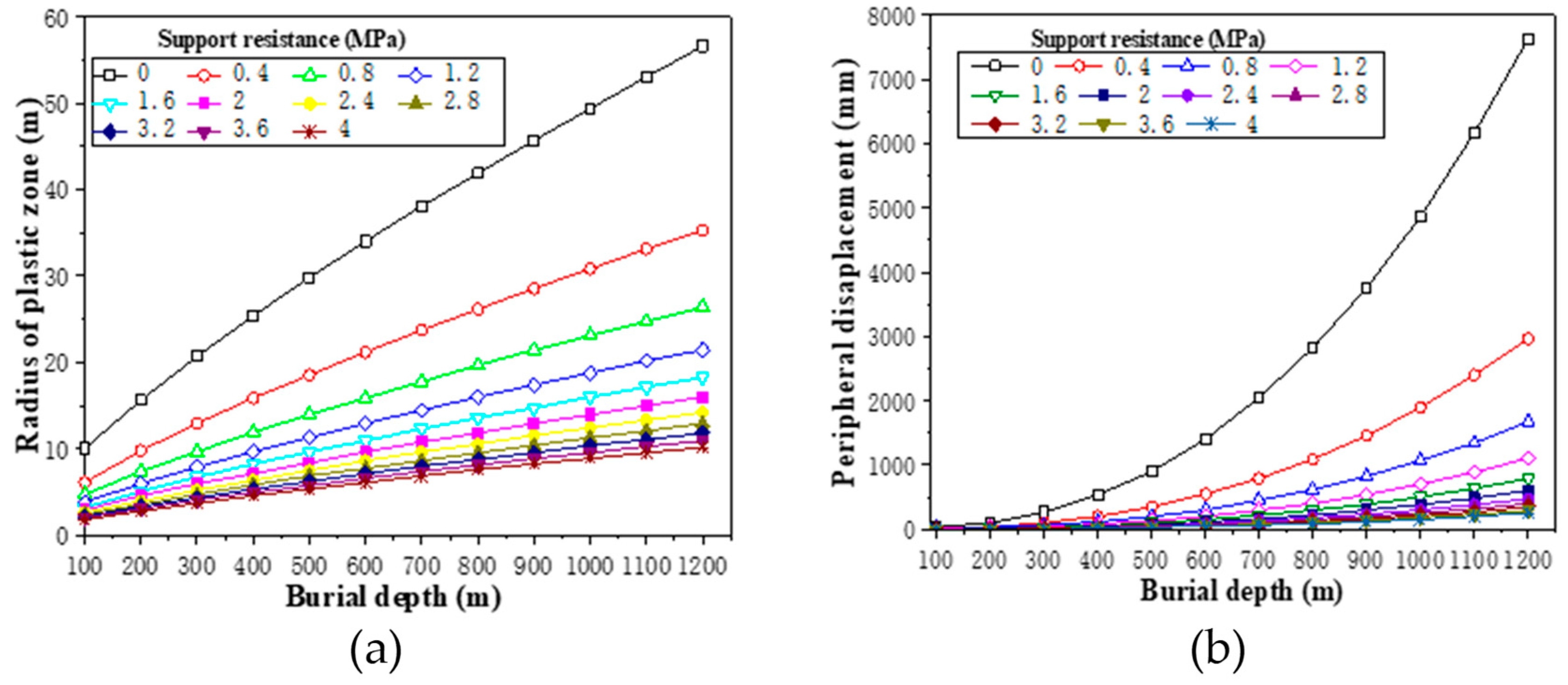
3.1. Effect of Tunnel Burial Depth
The burial depth of the tunnel is reflected in the vertical initial stress,
σy. The variation curve of the radius of the plastic zone with burial depth (tunnel radius = 4 m, internal friction angle = 23.5°, cohesion = 0.2 MPa) is shown in
Figure 1a. As can be seen from
Figure 1a, the radius of the plastic zone increases with the increase of tunnel burial depth. For example, when the support resistance is assumed to be 0.4 MPa, the radius of the plastic zone of the tunnel is 6.2 m at a depth of 100 m, and 12.9 m at a depth of 300 m.
The variation curve of peripheral displacement with burial depth (tunnel radius = 4 m, internal friction angle = 23.5°, cohesion = 0.2 MPa) is shown in
Figure 1b. It can be seen from
Figure 1b that the peripheral displacement increases sharply with the increase of tunnel depth. For example, when the support resistance is assumed to be 0.4 MPa, the peripheral displacement of the tunnel is 9.1 cm at a depth of 200 m, and 96.7 cm at a depth of 500 m. It is evident that the depth of the tunnel has a great influence on radius of the plastic zone and the surrounding displacement. From the later research, we can see that this property will be even more significant in soft rock tunnels.
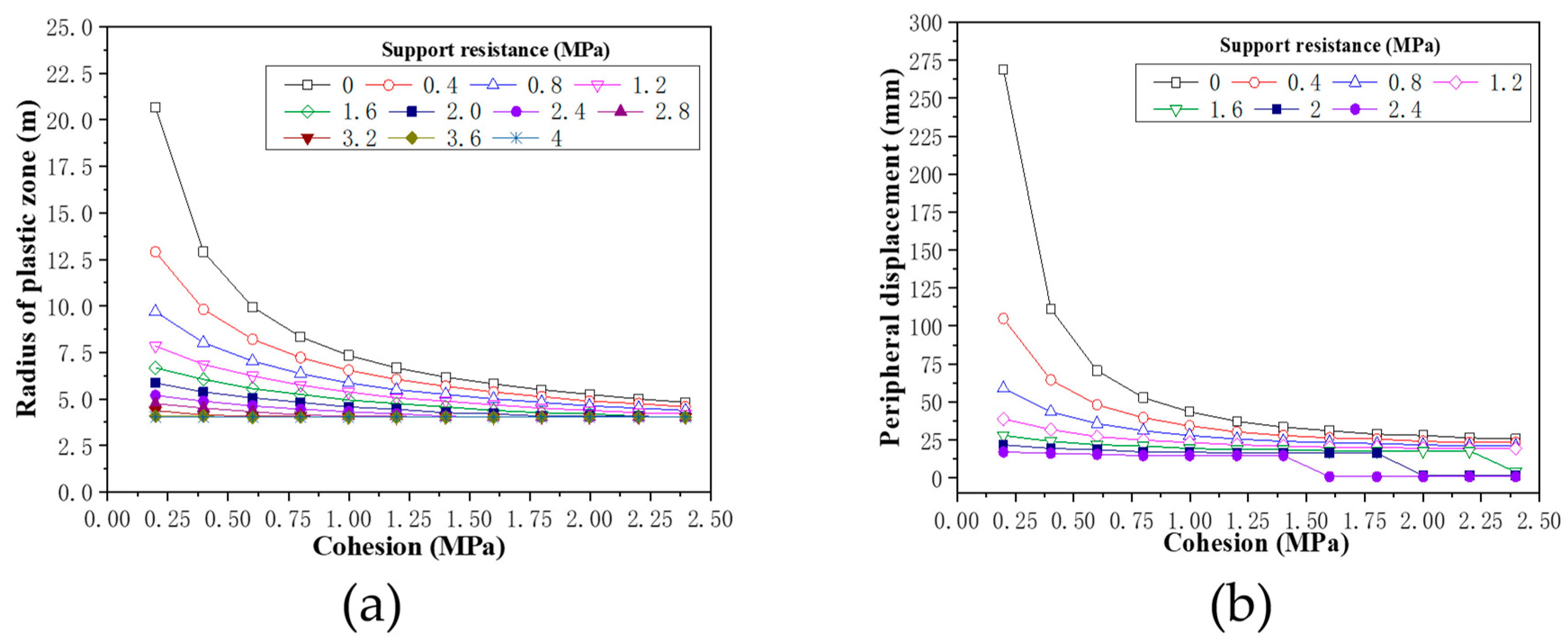
3.2. Effect of Rock Mass Strength
In Coulomb-Mohr strength theory, the main influencing factors of rock mass strength are cohesion and internal friction angle. Because the change of internal friction angle of different rock mass is relatively small, the strength of rock mass is usually expressed by cohesion. The variation curve of the radius of the plastic zone with cohesion of rock mass (tunnel radius = 4 m, internal friction angle = 23.5 °, burial depth = 300 m) is shown in
Figure 2a. As can be seen from
Figure 2a, the radius of the plastic zone decreases with the increase of cohesion. For example, the radius of the plastic zone of the tunnel is 20.7 m at a cohesion of 0.3 MPa without support, while at a cohesion of 1.0 MPa it decreases sharply to 7.4 m. This rule is very useful for the design of the bolt length.
The variation curve of peripheral displacement with cohesion of rock mass (tunnel radius = 4 m, internal friction angle = 23.5°, burial depth = 300 m) is shown in
Figure 2b. It can be seen from
Figure 2b that the peripheral displacement decreases sharply with the increase of cohesion. For example, the peripheral displacement of the tunnel is 26.9 cm at a cohesion of 0.2 MPa without support, while at a cohesion of 1.0 MPa it decreases sharply to 4.3 cm.
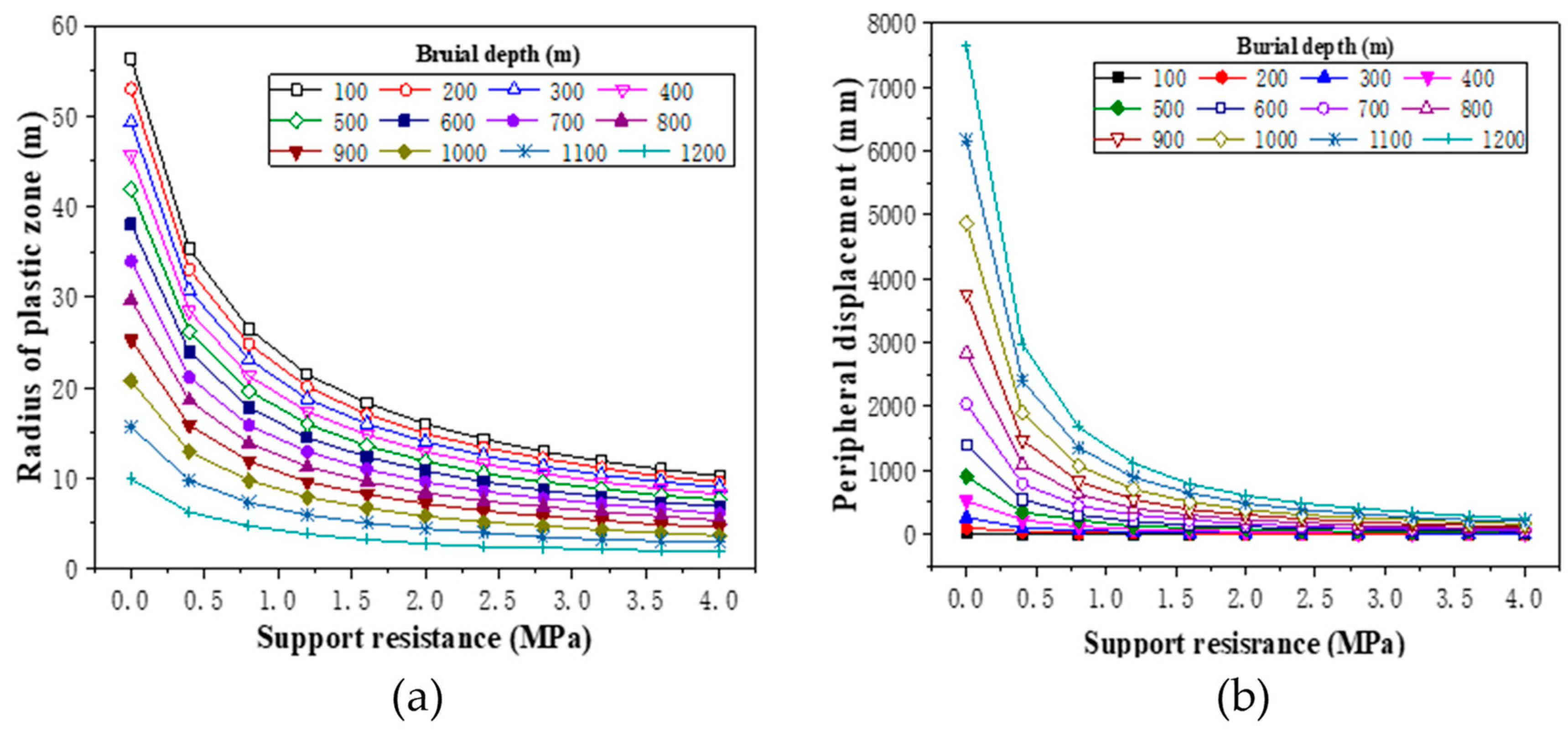
3.3. Effect of Support Resistance
The effect of supporting, is equivalent to exerting a resistance around the tunnel to prevent the deformation of rock mass. The result is that the support resistance changes the stress state of the rock mass which inevitably accompanies the development of deformation. The variation curve of the radius of the plastic zone with support resistance (tunnel radius = 4 m, internal friction angle = 23.5°, cohesion = 0.2 MPa) is shown in
Figure 3a. It can be seen that radius of the plastic zone decreases with the increase of support resistance. For example, when the tunnel burial depth is 300 m, the radius of the plastic zone of the tunnel is 20.7 m at support resistance of 0.3 MPa, while at support resistance of 0.8 MPa it decreases to 9.7 m.
The variation curve of peripheral displacement with cohesion of rock mass (tunnel radius = 4 m, internal friction angle = 23.5°, cohesion = 0.2 MPa) is shown in
Figure 3b. It can be seen from
Figure 3b that the peripheral displacement decreases sharply with the increase of support resistance. For example, when the tunnel burial depth is 300 m, the peripheral displacement of the tunnel is 268.9 mm without support, while with support resistance of 0.8 MPa it decreases to 58.8 mm. It can be seen that the influence of support resistance on the radius of the plastic zone and surrounding displacement is also great, especially in soft rock tunnel. In soft rock tunnel construction, reasonable supporting means are the main measure to control the deformation of soft rock.
The above theoretical analysis of tunnel mechanics reveals the stress and deformation law of rock mass in the process of excavation and support of soft rock tunnel in a two-dimensional state, and shows the influence of tunnel burial depth (initial stress field), rock mass strength (c, φ) and support resistance on the plastic zone and peripheral displacement after excavation and support of the soft rock tunnel. However, the rock mass of soft rock tunnel has obvious expansibility and rheological characteristics, and the deformation of rock mass will continue to change with time; thus, tunnel construction is a process of intersecting space and time effects, which are manifested in the space-time effect. Therefore, it is necessary to further analyze the excavation and support of soft rock tunnel according to the space-time effect.
4. Numerical Simulation of Excavation and Support
The Dongsong Hydropower Station is located in Ganzi Prefecture, Sichuan Province, China, at an altitude of over 2500 m. This paper is based on the No. 2 diversion tunnel with a vertical burial depth of about 300 m. Surrounding rock is mainly phyllite with weak and fractured rock mass. Because of high in situ stress, large deformation often occurs after tunnel excavation. The design section of the tunnel is horseshoe-shaped with an equivalent radius of 4 m.
In the three-dimensional numerical simulation analysis, the space-time effect is reflected by the stress release process in the excavation and support process, and the theory mentioned above is further improved.
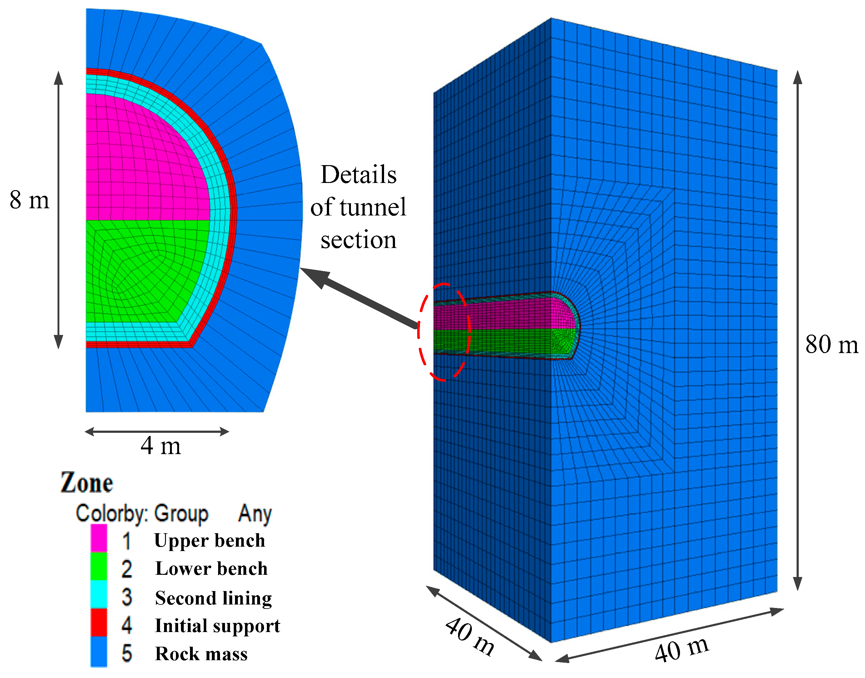
4.1. Numerical Model and Calculation Parameters
Taking the tunnel and rock mass as the research object, the model was established, and the Mohr-Coulomb model was selected as the constitutive model. The horizontal and vertical directions of the model are 80 m (about 10 times the diameter of the tunnel), and the mesh of the three-dimensional model is divided into 44,580 elements and 48,007 nodes, as shown in
Figure 4. The buried depth of the tunnel is 300 m, which makes it a deep-buried tunnel. Unlike shallow burial, terrain changes have little effect on the tunnel excavation. The initial in situ stress was applied according to the buried depth and the fixed displacement method was used for simulation. The normal displacement constraints were applied to the side and bottom of the numerical model, and the top was the free surface.
The rock mass of the diversion tunnel is dominated by phyllite. Based on the detailed geological exploration report, relevant codes and engineering analogy of the Dongsong Hydropower Station, the calculation parameters of the rock mass were selected as shown in
Table 1. The design and excavation section of the main diversion tunnel is horseshoe-shaped. The arch frame support is made of 18 I-steel with a longitudinal spacing of 100 cm. The bolt support adopts a mortar bolt with a length of 4.5 m and spacing of 1.5 × 1 m. Feet-lock bolts are constructed at the arch foot. Initial support is made of shotcrete with a strength of C20 (the standard strength of concrete is 20 MPa) and thickness of 20 cm. The spacing of the welded steel mesh is 15 cm (@ 15 × 15).
The second lining is made of mold casting concrete with a strength of C30 and thickness of 60 cm.
Rock mass was simulated by a solid element, arch support was simulated by a beam element, bolt support was simulated by a cable element, and concrete was simulated by a shell element. Welded steel mesh was not simulated separately, which was achieved by equivalent improvement of shotcrete parameters. The physical parameters of each supporting structure in practical engineering are shown in
Table 2.
In the simulation, the two-bench method scheme was adopted according to the actual construction. The upper and lower benches were excavated at the same time, and the excavation footages were kept unchanged. The excavation footage was 1 m per cyclic step, and initial support was constructed immediately after the excavation was completed. Assuming that initial support is in close contact with the rock mass, the buried depth of the tunnel was 300 m, and the lateral pressure coefficient was 1.0.
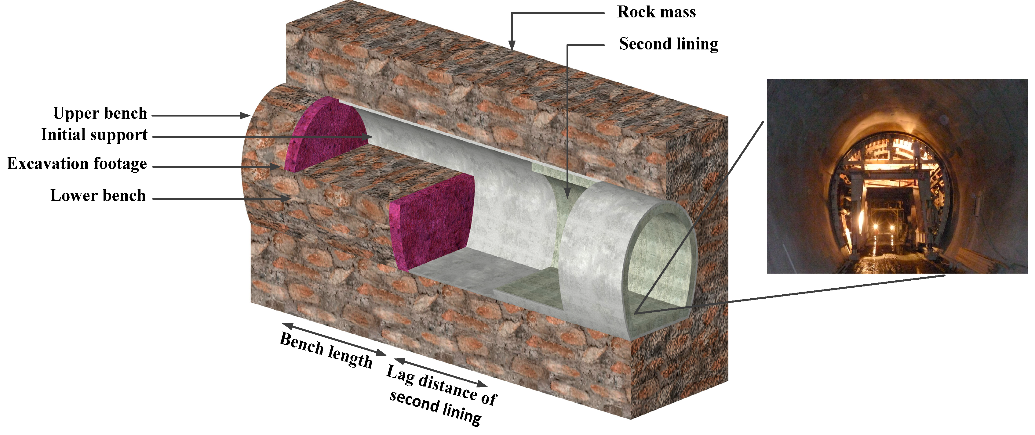
4.2. Determination of The Optimal Longitudinal Bench Length
During the excavation process with the bench method, the most critical factor affecting deformation of the tunnel is the length of the bench. In this section, the deformation of the tunnel under different bench lengths was simulated to determine the optimal bench length. A representation of the bench method is shown in
Figure 5.
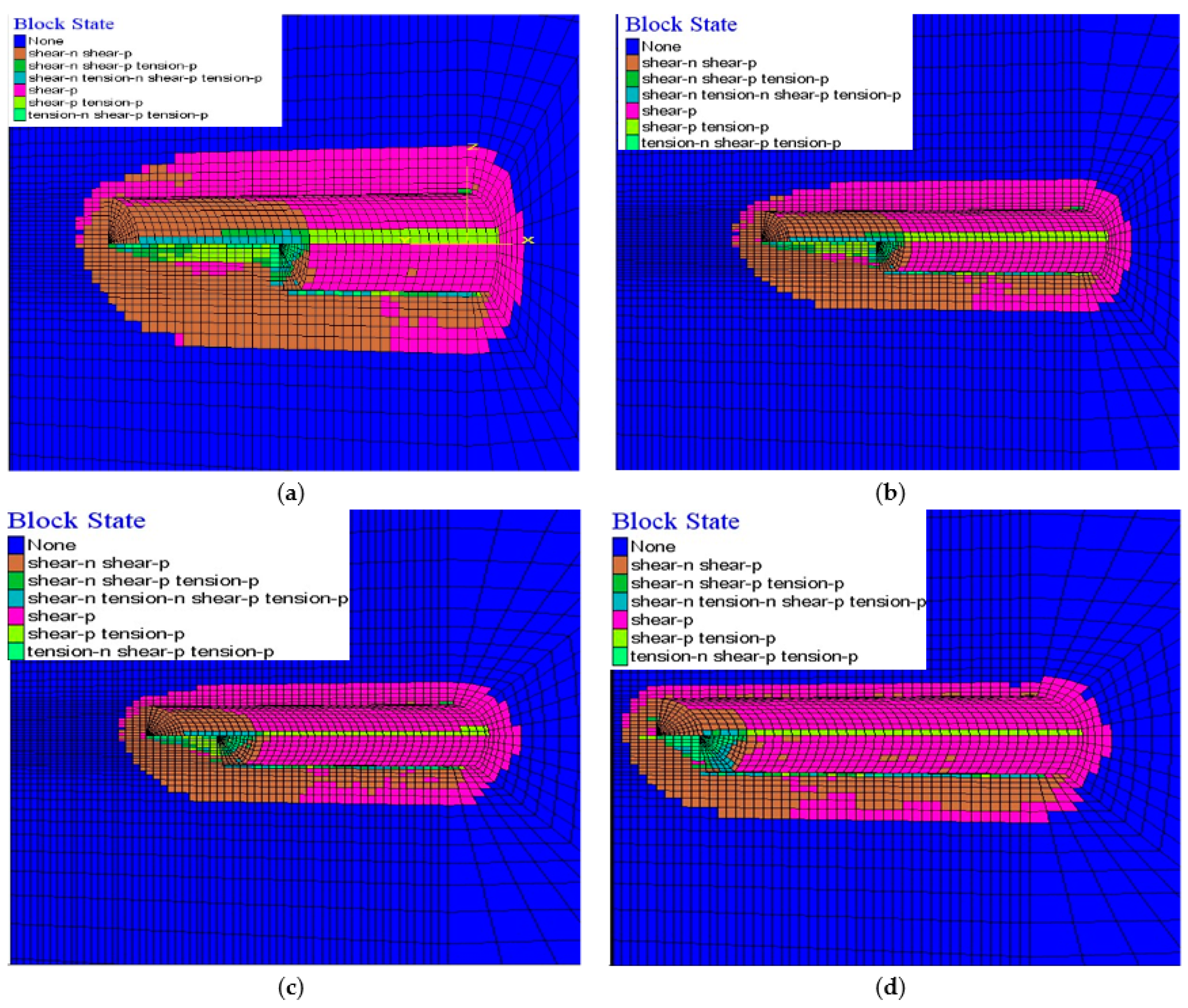
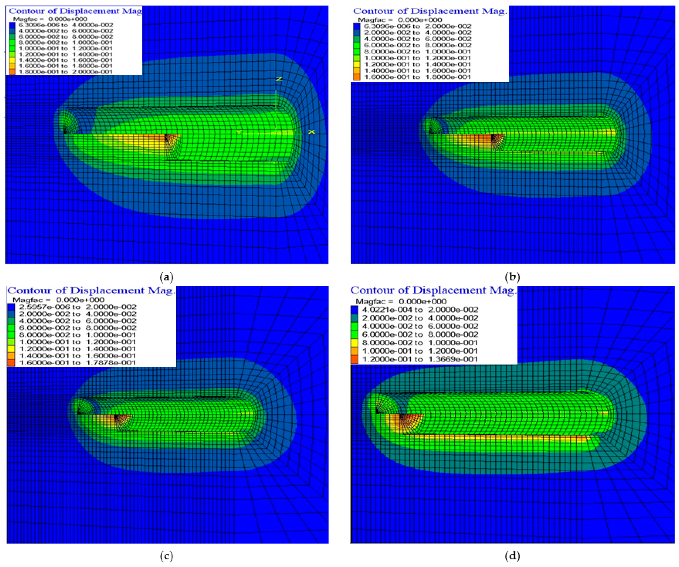
Four models with 5, 10, 15 and 20 m bench lengths, respectively, were selected for simulations. Calculation results of these models are shown in
Table 3. The distributions of peripheral displacement and the plastic zone with different bench lengths are shown in
Figure 6 and
Figure 7.
With the increase of the bench length, the vault settlement, sidewall convergence, bottom uplift, and longitudinal displacement of the tunnel face all clearly increase, while the axial force and bending moment of the steel arch frame tend to decrease. The total range of the plastic zone increases with the increase in bench length, and is mainly distributed at the bottom, the sidewalls and the tunnel face. The plastic zone near the tunnel face tends to decrease with the increase of bench length. This is because a bench with sufficient length can stabilize the tunnel face. Therefore, increasing the bench length can effectively control the development of the plastic zone of the tunnel face.
From the above conclusions, it can be further concluded that the short bench method can effectively control the deformation of the surrounding rock and the plastic zone. As shown in
Figure 6 and
Figure 7, the tunnel plastic zone and displacement decrease with the reduction of bench length, but a bench length that is too short makes it difficult for construction machinery to work (for example, the length of a rock drilling trolley is about 9~13 m). Considering that enough working intervals should be reserved on the bench in actual construction, the optimal bench length can be determined to be 10~14 m (about 1.5~2 D, where D represents the diameter of the tunnel).
4.3. Peripheral Displacement of Tunnel
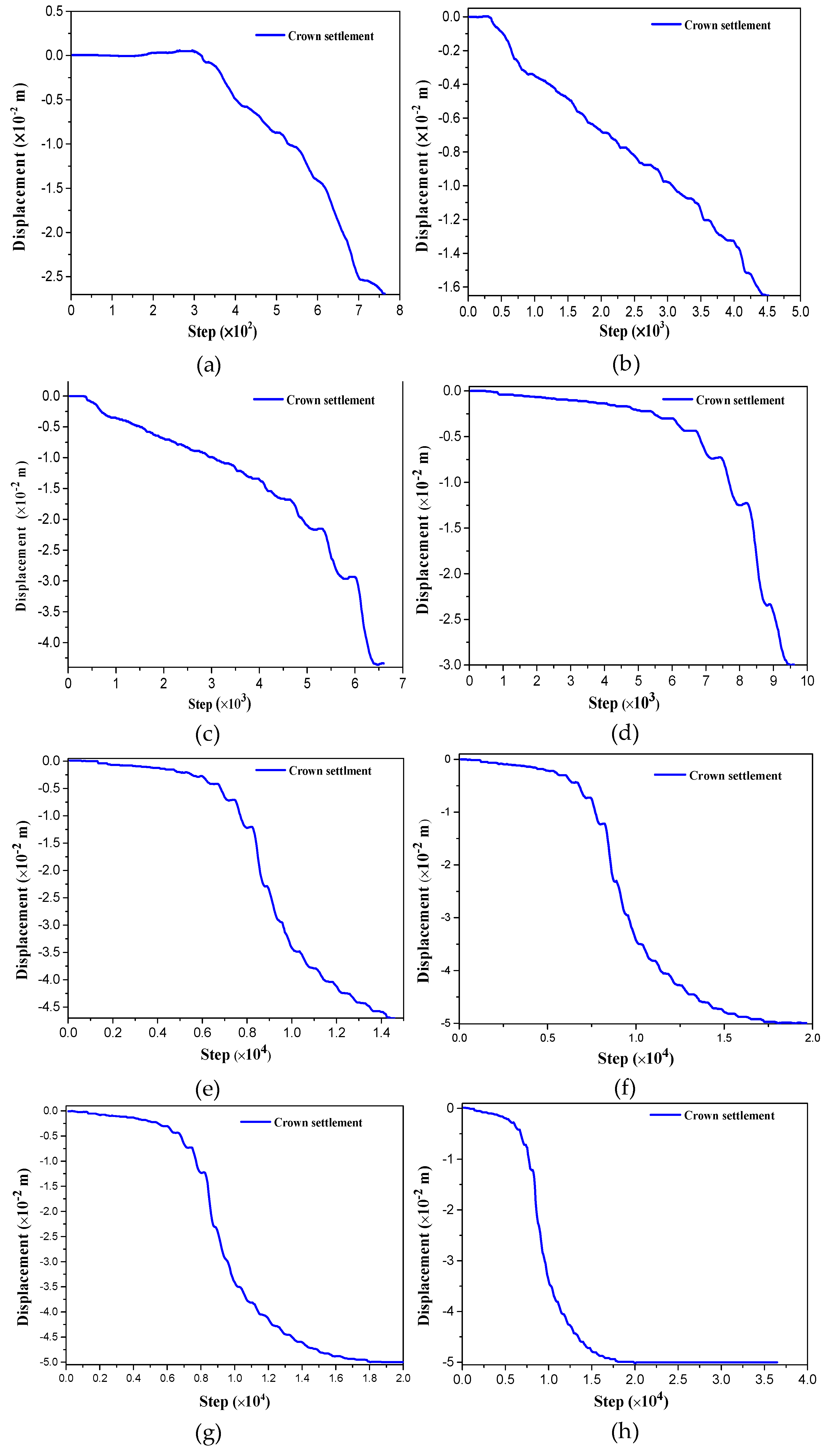
The model with the optimal bench length of 12 m, was selected for the simulation calculations here. When the upper bench face of the tunnel was excavated to different positions, the relationship between displacement and the time-history of the characteristic points (vault) of the tunnel monitoring section were sampled and recorded. When the tunnel was half excavated, the displacement data of the characteristic points were selected when the distance between the monitoring section and the upper bench face was −16 m (−2 D), −8 m (−1D), −4 m (−0.5 D), −0 m (D), 8 m (1 D), 16 m (2 D) and 32 m (4 D), respectively. The curves of the relationship between displacement and time-history are shown in
Figure 8. Displacement at monitoring points of the tunnel in the trial propulsion stage is shown in
Table 4. The negative sign indicates that the monitoring section is in the range of unexcavated rock.
As can be seen from
Figure 8 and
Table 4, the vertical displacement of the vault appears at the monitoring point of −2 D. Displacement reaches almost the maximum at the monitoring point of 4 D. The displacement release rate is the highest at the tunnel face (i.e., the maximum slope of the curve). Most of displacement occurs after the tunnel face is propelled through the monitoring point.
The statistical data of displacement and the time-history of the characteristic points of the monitoring sections were analyzed by the same method. When the tunnel face was propelled to the monitoring point, the displacement at this point reached about 11.5% of the total displacement (the displacement release rate was 11.5%). When the tunnel face was propelled at 2 D in front of the monitoring point, the displacement release rate reached about 80%. Meanwhile, analyses found that the change law of the curve was quite different below and above 0.5 D, so it is hard to fit with only one curve. Therefore, the curve is divided into two parts for fitting, using the curve Equations (14) and (15), respectively.
The fitting curve is shown in
Figure 9. Using Equations (14) and (15), the displacement release rate of any point at different distances from the tunnel face can be found. For example, the displacement release rate is 57% at 1 D and 85% at 2 D. Therefore, the displacement can be effectively controlled if the second lining is constructed in time at a position within 2 D (16 m) behind the tunnel face.
However, the construction of second lining should not occur too early. If it is constructed too early, it will not make full use of the bearing capacity of the rock mass and this will make the lining bear too much of the rock mass load. This may lead to the lining cracking due to excessive stress, which will affect the durability and safety of the tunnel structure. The surrounding rock of a soft rock tunnel is prone to large deformation after excavation. In order to prevent the initial support from invading the clearance after deformation, the excavation contour must be enlarged along the radial direction. The size of the enlarged radial direction is called the reserved deformation. Theoretically, the reserved deformation should be slightly larger than the total deformation around the tunnel in the process of excavation and support. Equations (14) and (15) and their fitting curves (
Figure 9) are very useful for estimating the reserved deformation and the effect of supporting structures.
The above theoretical analysis and numerical tunnel simulation reveal the changing law of the surrounding rock state during the process of excavation and support of a soft rock tunnel; however, it is based on an ideal state, which is different from an actual situation. When this is applied to practical engineering, we should also consider aspects of the actual engineering construction, such as the inhomogeneity of the rock mass, tectonic crustal stress, etc.
The inhomogeneity of surrounding rock can be obtained by in-situ geological observation and advanced geological prediction. In this project, the occurrence and strike of phyllite should be considered. Except for some sections, most sections are fractured, the attitude of the bed is complicated, irregularity is obvious, and the inhomogeneity is clear. In terms of tectonic crustal stress, the project is located in a complex fault zone. The tectonic crustal stress is very complex, which has the greatest impact on the project. Its direct impact is the irregularity of deformation of the rock mass. Therefore, it was necessary to improve the above research results combined with field monitoring data.
5. In-time Feedback of Monitoring Data
The above research results were applied to tunnel construction in a large deformation section of soft rock. Through tracking the implementation of the scheme and field monitoring data, the research results were checked and improved, and in-time feedback provided for the tunnel construction.
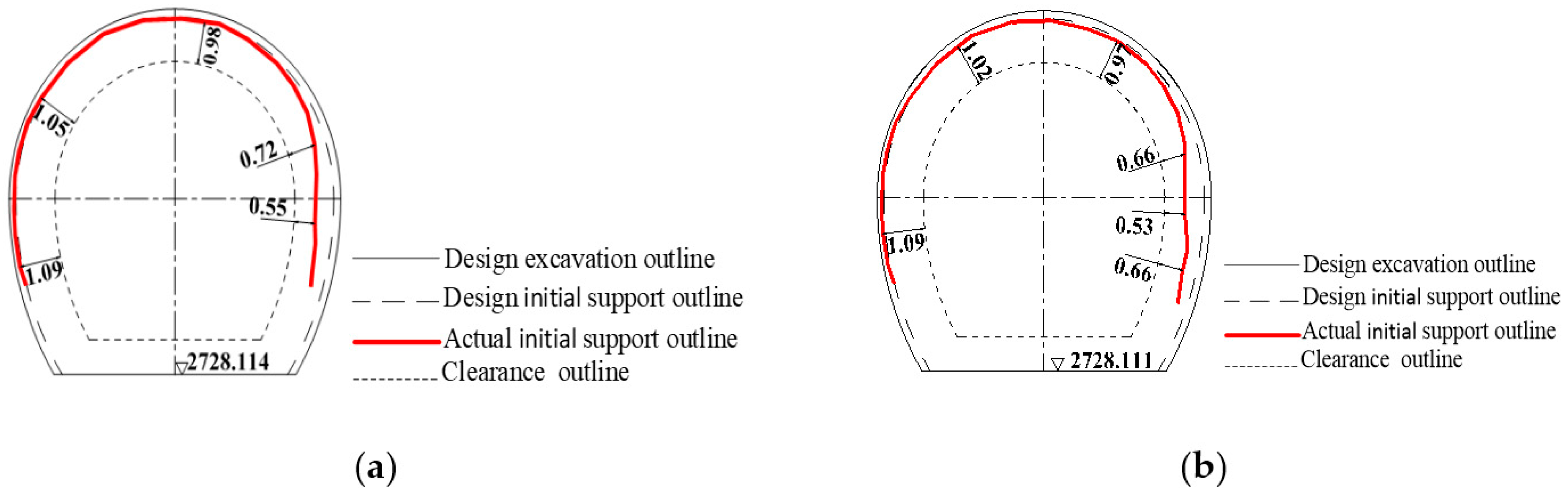
Section 4 of this paper showed that the settlement of the vault was 5 cm and the convergence of the sidewall was 8.5 cm. On this basis, the support outline was designed, and the reserved deformation was 10 cm, as shown in
Figure 10,
Figure 11 and
Figure 12. It can be seen that the construction of the initial part of tunnel (
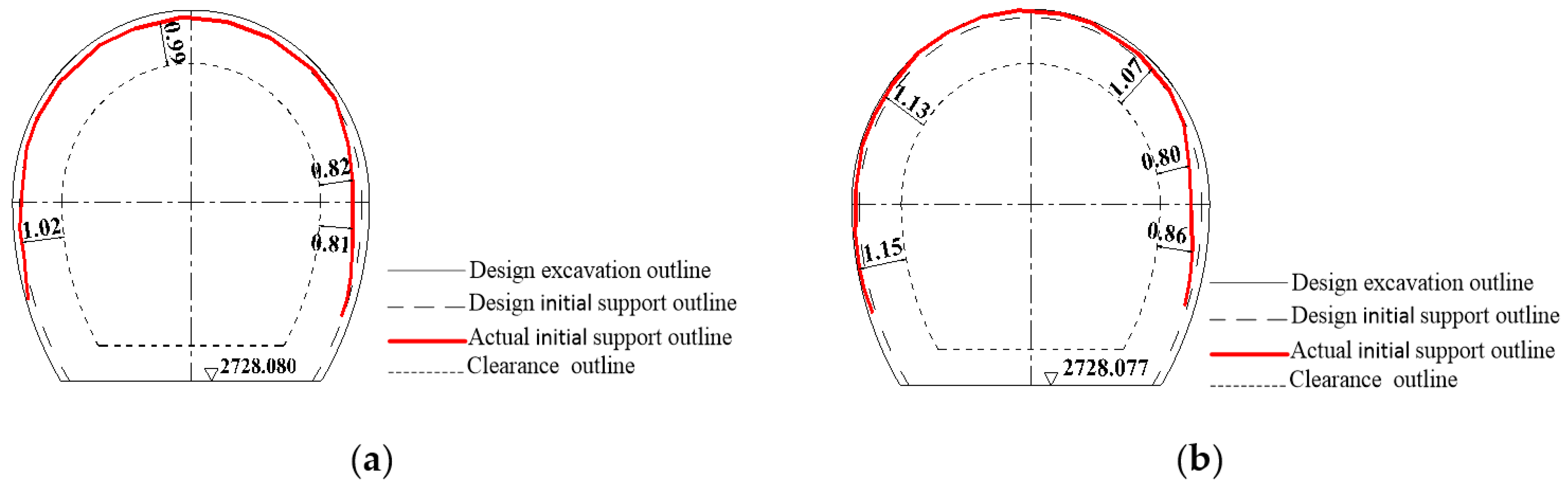
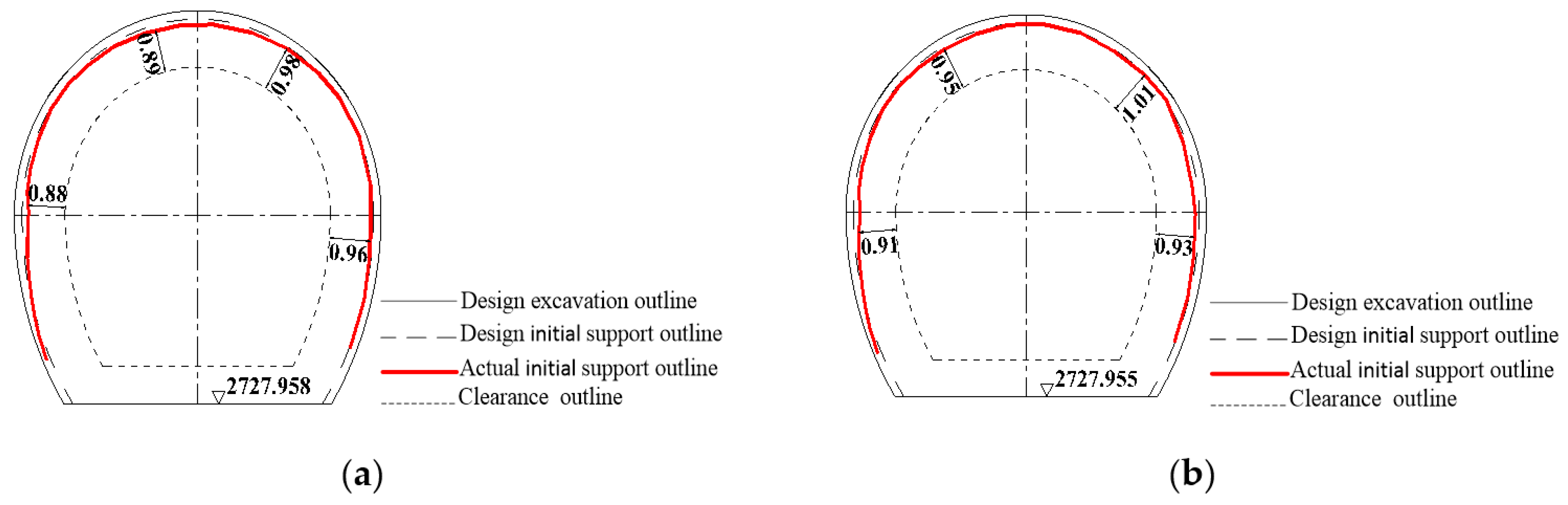
Figure 10) is guided by the construction suggestions given above. The actual support outline of the tunnel in this section is mostly consistent with the design, but the displacement of the right sidewall is too large. In order to ensure adequate thickness of the second lining (60 cm), the inner outline of second lining is not allowed to intrude into the tunnel clearance outline. Feedback on this situation was provided in time for later construction; e.g., to expand and excavate the right wall appropriately and increase the reserved deformation to 35 cm and construct the second lining a little earlier. It can be seen that the final deformation of the tunnel has been effectively controlled to meet the design and construction requirements from the construction of the middle and terminal parts of tunnel (
Figure 11 and
Figure 12).


