Article

Yttria Ceria Co-Stabilized Zirconia Reinforced with Alumina and Strontium Hexaaluminate

Institute for Manufacturing Technologies of Ceramic Components and Composites (IFKB), University of Stuttgart, Allmandring 7b, D-70569 Stuttgart, Germany
*
Author to whom correspondence should be addressed.
Appl. Sci. 2019, 9(4), 729; https://doi.org/10.3390/app9040729
Submission received: 29 January 2019 / Revised: 12 February 2019 / Accepted: 18 February 2019 / Published: 20 February 2019
(This article belongs to the Special Issue Ceramic Composites and Films)

Abstract

:

Featured Application

Zirconia-based ceramics with a combination of high strength, toughness, and low-temperature degradation resistance are required not only for biomedical applications, but also for other engineering applications operating under high load associated with the risk of catastrophic failure.

Abstract

Zirconia materials are frequently used in dental applications due to their excellent strength and their tooth-like aspect. Standard yttria stabilized zirconia (Y-TZP) ceramics suffer, however, from moderate toughness and vulnerability to low-temperature degradation. In this study, 1Y6Ce-TZP materials reinforced with different amounts of alumina and/or strontium hexaaluminate were manufactured by slip casting and pressureless sintering at different temperatures to assess their mechanical properties, microstructure, phase composition, and low-temperature degradation stability. Results show that these materials exhibit a high fracture resistance of 10–12 MPa√m, a bending strength between 700–950 MPa, and a Vickers hardness of 1100–1200 HV10. Strontium hexaaluminate (SA6) precipitates were formed in situ by reaction of alumina and strontium zirconate. Although crack deflection at SA6 platelets was clearly visible, a net toughening was not observed. Accelerated ageing tests at 134 °C/3 bar water vapor pressure showed best results for mixed alumina/SA6 reinforcements and a sintering temperature of 1500 °C. Mehl-Avrami-Johnson plots used to describe the ageing kinetics showed clear indications of different ageing mechanisms due to the introduction of the SA6 phase.

1. Introduction

The excellent mechanical properties of partially stabilized zirconia are caused by transformation toughening (TT), a stress-induced martensitic transformation of metastable tetragonal phase to stable monoclinic phase [1]. This phase transformation, in the wake of a proceeding crack, is associated with volume expansion and shear, which reduce the stress intensity at the crack tip, i.e., TT enhances the fracture resistance and, thereby, the strength. Zirconia has to be stabilized with iso- or aliovalent dopants, such as magnesia, yttria, or ceria, in order to retain the metastable tetragonal phase [2,3]. In tetragonal zirconia polycrystals (TZP), either yttria or ceria are used as stabilizers, which leads to either very strong materials with moderate toughness (Y-TZP) or extremely tough materials with moderate strength (Ce-TZP) [4]. Another critical aspect, especially in biomedical applications issue, is low-temperature degradation (LTD) [5]. LTD may occur when tetragonal zirconia is in contact with polar liquids. Y-TZP contains oxygen vacancies for charge neutrality due to the addition of trivalent yttrium. During LTD, the stabilizer is hydrolyzed, which eliminates these vacancies and results in spontaneous transformation to monoclinic without applied stress. Ce-TZP contains tetravalent Ce4+ and, therefore, no oxygen vacancies are created, which makes the solid solution extremely stable to LTD [6,7]. The concept of tailoring the properties of TZP by combination of ceria and yttria was elaborated in detail by Lin, who published maps of properties depending on the stabilizer composition [8,9]. Addition of alumina to TZP leads to an improvement in strength and hardness. In the case of Ce-TZP, alumina is added to avoid an autocatalytic transformation behavior of Ce-TZP, which is difficult to control [10,11]. Recent publications on Ce-TZP/alumina composites showed further improvements by a nanoscale microstructure and adjustment of the ceria stabilizer content [12,13,14]. In the case of Y-TZP, alumina doping (<0.5 vol%) enhances ageing resistance drastically due to the incorporation of alumina into the grain boundaries [15]. Alumina reduces the water/hydroxide diffusivity along grain boundaries [16]. Alumina addition in larger quantities (alumina toughened zirconia, ATZ) reduces transformability and fracture resistance, but increases strength, provided that the microstructure is dense, defect-free, and homogeneous [17,18]. ATZ materials are, therefore, typically hot-isostatically pressed [11]. The introduction of strontium hexaaluminate (SA6) to Ce-TZP was first described by Cutler [19]. The hexaaluminate phase was formed in situ according to (Equation (1)):
2   S r Z r O 3 + 12   A l 2 O 3   2   S r A l 11 O 19 + 2   Z r O 2
The aim was to obtain higher fracture resistance than in Ce-TZP/alumina and still control the autocatalytic transformation.
Other hexaaluminate reinforcements of magnetoplumbite (e.g., BaAl12O19, MnCeAl11O19), or β-aluminate (LaAl11O18, CeAl11O18) type were also successfully tried by different authors [20,21,22,23]. It was found that the type of hexaaluminate added strong influences the fracture behavior and the contribution of different reinforcement mechanisms. Forming hexaaluminates in situ by a solid state reaction offers the benefit of good sinterability, while addition of plate-or rod-shaped reinforcement phase to the starting powders may impede sintering due to the high aspect ratio of the reinforcement [24]. In a recently published feasibility study, it was found that a combination of a 1Y6Ce co-stabilized TZP with 10 vol% alumina and 10 vol% SA6 showed an attractive combination of high strength and toughness [25]. The present systematic study tries to show how subsequent substitution of alumina by SA6 affects mechanical properties, microstructure and LTD characteristics of such composites.

2. Materials and Methods

The starting powders for the study were monoclinic zirconia (d50 = 300 nm, SBET = 7 m²/g), α-alumina (d50 = 300 nm, SBET = 8 m²/g), yttria (purity 99.9%), ceria (purity 99.9%), and strontium zirconate (d50 = 5 µm, purity 99%). In a first powder technological step, the monoclinic zirconia was coated with 1 mol% of yttria according to the nitrate route, as described in detail elsewhere [26,27]. The coating process was chosen to avoid inhomogeneous yttria distribution. Four basic starting powders were produced by replacing alumina by SA6 in 5 vol% increments (see Table 1).
The 1Y-TZP was then blended with commensurate amounts of ceria, alumina, and strontium zirconate. As strontium zirconate contains no yttria stabilizer, the lack of stabilizer in the hexaaluminate systems must be compensated by addition of yttria (0.99 g Y2O3/100g SrZrO3). Four individual batches of 400 g solids mixture were dispersed in 133 mL of distilled water containing 4 mL of a commercially available ammonium citrate-based dispersant (CE64, Zschimmer&Schwarz, Germany). The dispersions were attrition milled for 2 h at 400 rpm using 600 g of Y-TZP balls of 2 mm diameter. Ten minutes before the end of the milling process, 4 mL of a polyacrylate-based binder (AC95, Zschimmer&Schwarz, Germany) and two drops of de-foaming agent (Contraspum, Zschimmer&Schwarz, Germany) were added. The efficiency of the milling process was monitored by laser granulometry (Malvern Mastersizer, GB). Mean particle sizes after 2 h milling were d50 = 0.46–0.48 µm in all cases (d10 ~ 0.2 µm, d90 ~ 1.1 µm). The dispersions were then passed through a 50 µm mesh to remove milling debris and, subsequently, stirred at 200 mbar in a vacuum chamber to remove entrapped air. Samples of ~ 45 × 35 × 6 mm³ were then produced by slip casting on a plaster plate (Hartenfels Gipsformen, Ransbach-Baumbach, Germany) using rectangular silicone frames. After green body formation, the samples were removed from the plate, carefully pre-dried in a powder bed of γ-alumina (25 m²/g) for one day and dried in an oven overnight at 85 °C. Subsequently, the samples were pre-fired in air (Linn High Therm, Eschenfelden, Germany) at 800 °C for 1 h, heating rate 60 K/h. Sintering was carried out in air at 1500–1550 °C (25K increments) for 2 h. The heating rate was 120 K/h to 1100 °C and 20 K/h from 1100 °C to final sintering temperature (Thermconcept, Bremen, Germany). The sample nomenclature, therefore, is extended by the sintering temperature (e.g., 1Y6CeTZP-15 vol% alumina sintered at 1550 °C = 15A-1550). The sintered samples were automatically ground (250 µm diamond disk), lapped, and polished with diamond suspension until a mirror-like surface was obtained (Struers ApS, Ballerup Denmark). The measurement of density (Archimedes’ method), Young’s modulus (impulse excitation, IMCE Belgium), and Vickers hardness HV10 (Bareiss Prüfgerätebau GmbH, Oberdischingen, Germany, five indents each) was carried out using entire plates. The plates were then cut into bending bars of ~2 × 4 × 25 mm³ size for mechanical testing. The sides of the bars were lapped to remove the cutting grooves and the edges were beveled by grinding with a 20 µm diamond disk. Bending strength σ4pt (>10 samples each) and the fracture resistance KISB by indentation strength in bending (ISB, five samples each) were measured in a four-point setup with 10 mm inner and 20 mm outer span (Zwick Roell, Ulm, Germany) [28]. The crosshead speed was 0.5 mm/min for the strength and 2.5 mm/s for the residual strength measurements. For the ISB test, the bars were notched with an HV10 indent in the middle of the tensile side with cracks parallel and perpendicular to the sides and measured immediately afterwards. For scanning electron microscope (SEM) studies of the microstructure (Carl Zeiss AG, Oberkochen, Germany, in lens, secondary electrons, 10 kV), the polished samples were thermally etched in air (1350 °C/10 min). The monoclinic content in polished surfaces, fracture surfaces and hydrothermally aged surfaces (Autoclave test, 134 °C, 3 bar saturated water vapor, exposition times 1–100 h, a fresh sample was used for each ageing time and composition) were determined by X-ray diffraction (X’Pert MPD, Malvern Panalytical, Royston, UK, Bragg-Brentano setup, Cu(Kα1)). The monoclinic and tetragonal peaks in the fingerprint range between (27–33° 2θ) were integrated and the monoclinic contents were calculated according to the calibration curve of Toraya [29]. The size of transformation zones, h, can be calculated according to Kosmac [30]. Transformation toughness increments were estimated from measured data according to McMeeking using a transformation efficiency X = 0.27 as for Y-TZP [31]. The results of the ageing test were plotted using a (Mehl-Avrami-Johnson, MAJ) nucleation and growth model [6]. In order to compensate for monoclinic phase Vm° present before ageing, a modified MAJ-equation Vm(t) − Vm° = 1-exp[-(kt)n] is used. (t = ageing time, k = rate constant, n = nucleation factor).

3. Results

3.1. Microstructure and Crack Deflection

Figure 1 shows a comparison of microstructure of samples with 15 vol% alumina (15A) and 15 vol% strontium hexaaluminate (15SA6) material sintered at 1500 °C and 1550 °C. In the 15A composites, the alumina is homogeneously distributed and most alumina grains occupy the junctions between zirconia grains. Some intragranular alumina grains trapped inside the TZP matrix grains were detected. In the 15A materials, the alumina grains retain their original grain size (starting powder: d50 = 300 nm), while the average size of TZP grains grows from 1.2 µm at 1500 °C to 1.6 µm at 1550 °C. The 15SA6 materials show plate shape SA6 precipitates which can be either single or multiple stacked lamellae (see Figure 1b,d). The average size of the SA6 precipitates does not change with sintering temperature. SA6 platelets have an aspect ratio of ~3–5, a length of 3–6 µm, and a thickness of 0.5–1 µm. Zirconia grains inside SA6 precipitates are more frequently observed at low sintering temperature. Grain growth in the TZP matrix is more pronounced in SA6-rich composites due to the larger size and lower number of SA6-grains compared to alumina grains.
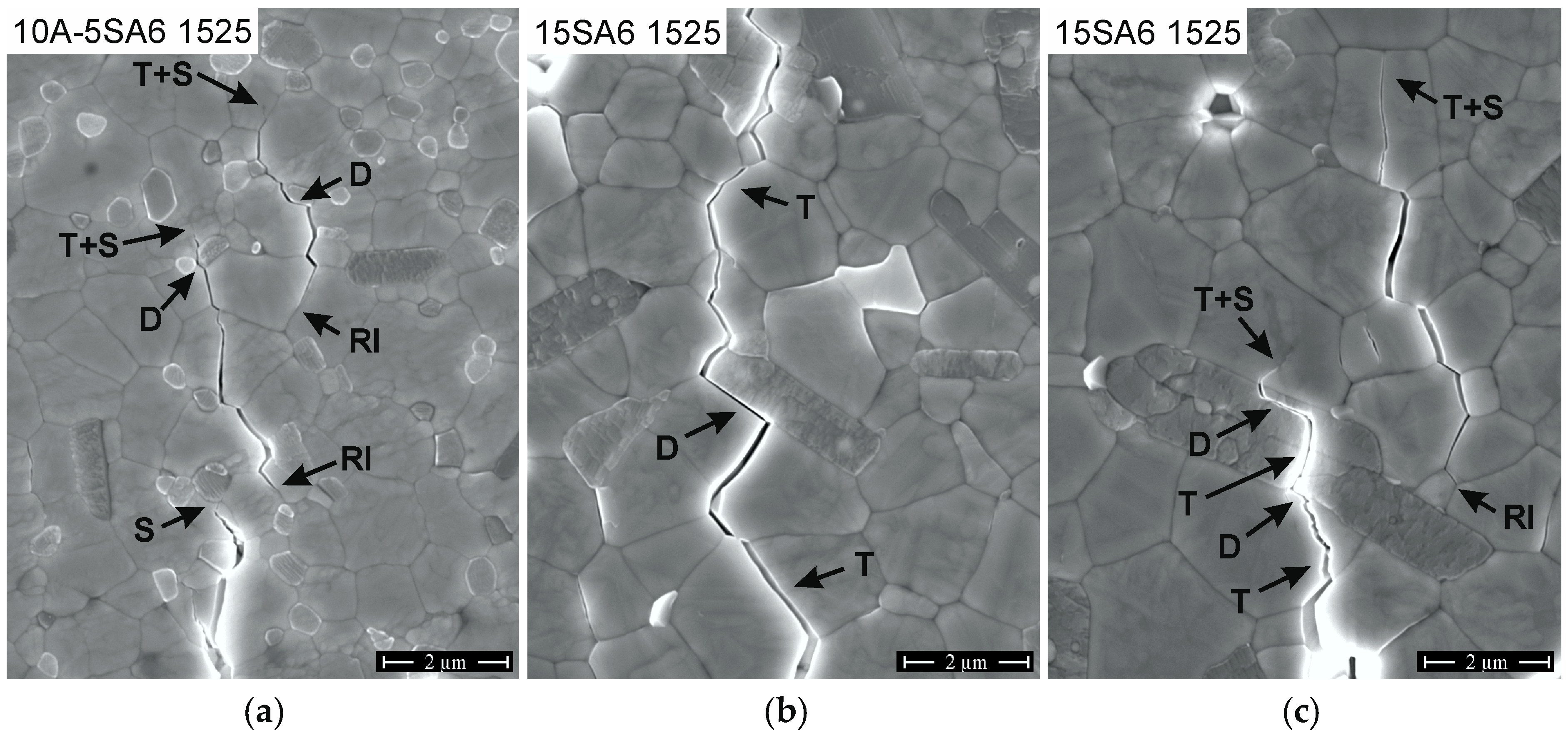
Wing cracks originating from the HV10 indents were studied to observe how the cracks interact with the different elements of the microstructure, especially with the SA6 platelets. Some examples are shown in Figure 2. Evidently, crack deflection does not only happen at SA6 precipitates. The TZP matrix typically shows intergranular crack propagation. Fracture of alumina grains is not observed (Figure 2a). Depending on the angle of incidence, the orientation of adjacent zirconia grains and grain boundaries either debonding (D) of the alumina/TZP boundary occurs (the most frequent effect), the crack is stopped (S) or enters adjacent zirconia grains causing transgranular fracture (T) (Figure 2a). Moreover, cracks can be stopped in the tough matrix and be reinitiated in a distance of a few µm (RI). In the 15SA6 composites, crack deflection at TZP/SA6 boundaries (D) is observed (Figure 2b). SA6 grains as obstacles in the crack paths may, moreover, lead to more complex interaction (Figure 2c). Here, the crack first breaks through a TZP grain (T), is then deflected (D) for a short distance along the TZP/SA6 boundary. Then, the crack breaks through the SA6 platelet (T), exits along the SA6/SA6 lamella boundary (D), and is stopped in the TZP matrix. Approximately 2 µm away from this location, the crack is reinitiated (RI) along a TZP/TZP grain boundary until it is finally terminated within a transgranularly fractured TZP grain (T).

3.2. Density and Mechanical Properties

Relative density (not shown in detail) reached >99.4% of theoretical for composites sintered at 1500 °C and reached 100% at 1550 °C so that the sintering conditions can be considered sufficient in all cases to fully densify the materials. The Young’s modulus E (not shown in detail) was in a close range between 213–217 GPa. A slight trend to decline with progressive alumina substitution by SA6 was detected which, however, did not exceed the range of the standard deviation of measurements (± 4 GPa). Figure 3 shows the Vickers hardness of the composites depending on composition and sintering temperature.
The hardness shows a declining trend with increasing SA6 content, which starts at SA6 fractions >5 vol%. 15A and 10-5SA6 materials show a hardness HV10 of 1180 HV10. Then, the hardness declines linearly to 1120 HV10 for 15SA6.
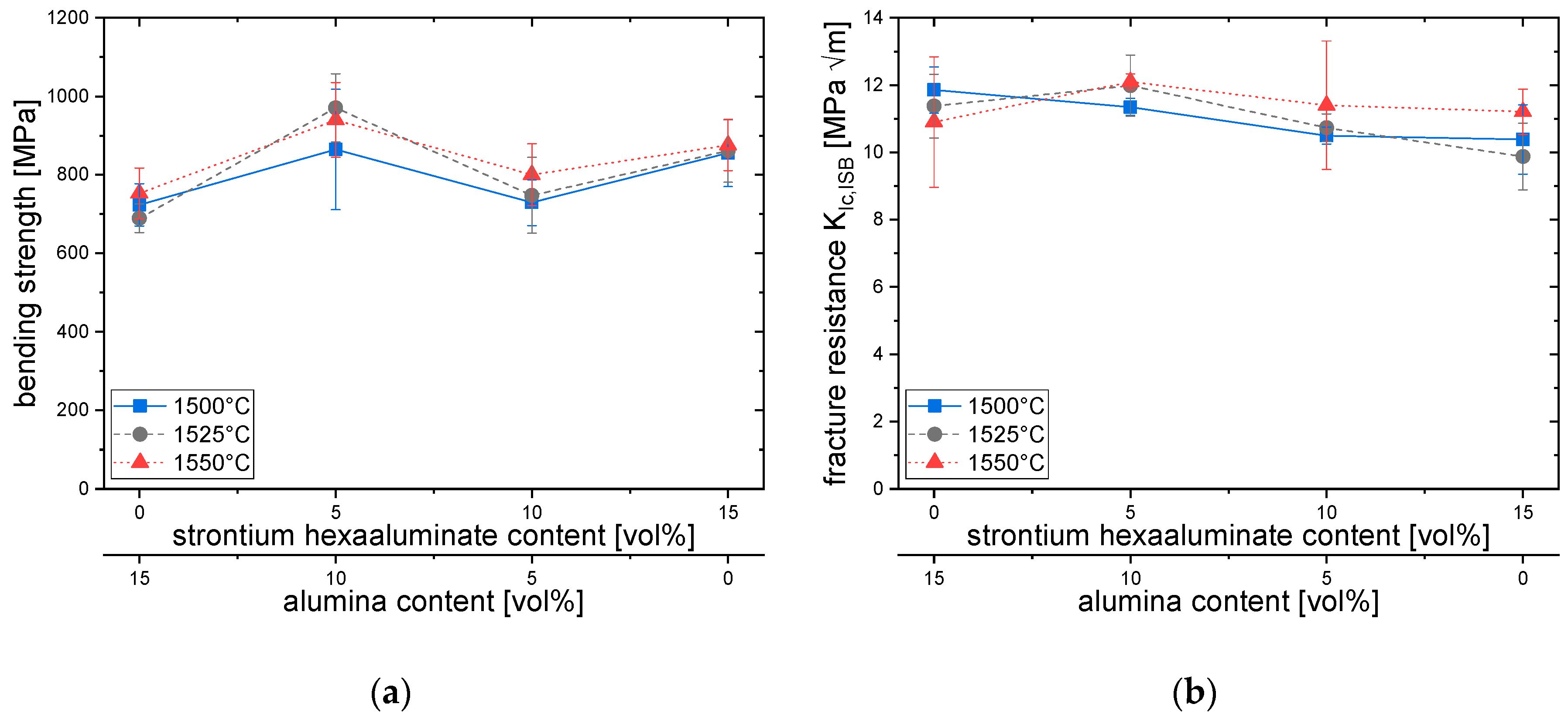
Figure 4a shows the bending strength σ4pt of the composites. A slight improvement with increasing sintering temperature can be observed. As far as the SA6 fraction is concerned, no clear trend is visible. 10A-5SA6 composites show the highest bending strength of 860–970 MPa, while the lowest strength is found in 15A materials (690–750 MPa). Between 5–15 vol% SA6, an intermediate minimum at 720–810 MPa is observed. 15SA6 materials all reach strength values of ~860 MPa.
The fracture resistance KISB is shown in Figure 4b. All materials show a very high fracture resistance of >10 MPa√m. The maximum toughness of 12.5 MPa√m is reached for 5A-10SA6-1550. This material also shows excellent strength. In case of materials with lower strength (15A or 10A-5SA6), it must be considered that the measured residual strength is very close to the bending strength. This means that for these samples with a bending strength of <700 MPa there exists an upper limit for measurable toughness at ~11.5 MPa√m, as the residual strength cannot be higher than the bending strength. The “real” toughness could be even higher. The general trend shows a slight decline in toughness with increase in SA6 content and a slight increase with increasing sintering temperature.

3.3. Phase Composition and Transformation Toughness

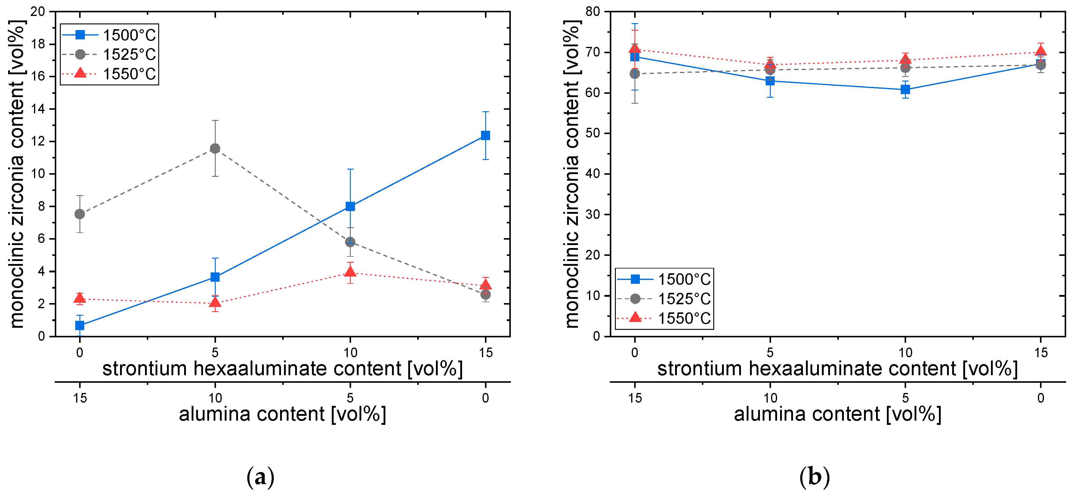
The monoclinic content Vm,pol in the polished surface of the composites is shown in Figure 5a. Surprisingly, the materials sintered at the highest temperature show the lowest monoclinic content (2–4 vol%), while the monoclinic content in materials sintered at lower temperature can be as high as 12 vol%. A general trend describing monoclinic content versus sintering temperature and SA6 fraction cannot be seen. Figure 5b shows the corresponding monoclinic content Vm,f in fractured surfaces. In the fractured surfaces, 52–68 vol% monoclinic can be found. Here, the SA6 contents seems to have little influence, while increasing sintering temperature leads to a higher transformed fraction. The difference Vf = Vm,f − Vm,pol is the stress-induced transformability of the zirconia materials. The highest transformability Vf of up to 65 vol% can be identified in materials sintered at 1550 °C. High transformability implies high transformation toughness. However, the transformation efficiency X in the McMeeking formula (Equation (2)) is not known. A priori it was assumed that X = 0.27 (predominantly dilatoric) as in Y-TZP [4].
Δ K I c T =   X / ( 1 ν ) V Z V f E ε h
(with X = transformation efficiency, ε = 0.054 = Volume change due to transformation, ν = Poisson’s ratio = 0.31, h = depth of transformed zone, Vz = zirconia content = 0.85).
The calculation of transformation toughness increments leads to values between 4–5.5 MPa√m. Materials sintered at 1550 °C tend to the upper limit of this range. Transformation toughness is, therefore, the dominant reinforcement mechanism, but cannot fully explain the high toughness. In a previously published paper, the threshold toughness of a compositionally similar 1Y6Ce-10A-10SA6 composite was measured (KIO = 4.6 MPa√m) [25]. It can be estimated that in the present case depending on the material the R-curve dependent part of toughness amounts to KIC − KIO = ~ 6–7 MPa√m. Assuming toughening effects to be additive, we may, therefore, estimate the contribution of other reinforcement mechanisms, such as crack bridging, crack deflection, and microcracking at 1.5–2.5 MPa√m [32].

3.4. Low Temperature Degradation

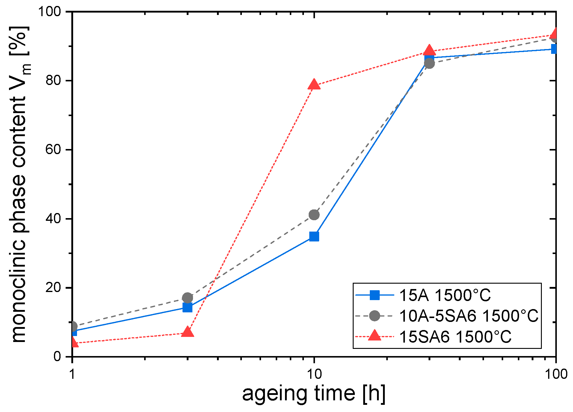
Figure 6 shows some selected plots (illustrating the spread between different materials) of monoclinic content Vm versus ageing time ta as a result of the accelerated autoclave ageing tests carried out.
The monoclinic content rises from values lower than 10 vol% (ta = 0) to values of 87–97 vol% with increasing ageing time (see Figure 6). This indicates the absence of non-transformable cubic phase and shows that the material shows severe ageing after prolonged exposition to water vapor. According to a recent publication by Wei and Gremillard the correlations between microstructure, sintering conditions composition and ageing kinetics are complex [33]. Data on Y-Ce-TZP are yet not available. Emanating from a simplistic a priori assumption, we may guess that the time relevant for biomedical applications is ta = 10 h, which corresponds to 30–35 y in vivo, a realistic upper lifetime limit for a biomedical implant. At this ageing time, a large spread between 30 vol% monoclinic (5A-10SA6-1500) and 78 vol% monoclinic (15SA6-1500) in two seemingly identical materials sintered at low temperature is observed. The materials with the highest strength and toughness (5A-10SA6-1525 and -1550) show monoclinic contents in the 40% range at ta = 10 h.
MAJ plots can provide more information on ageing kinetics. Please note that, in order to avoid misinterpretations, the initial monoclinic content Vm° at t = 0 was subtracted. Figure 7a–d shows MAJ plots of all materials including information about their nucleation factor, n. Evidently, the data points cannot be explained by a single linear fit. Short ageing times and long ageing times must be considered separately. Therefore, only the first-stage ageing behavior was linearly fit to calculate the nucleation factor, the coefficients of determination for the linear fits containing 3–4 data points in Figure 7 are significant (R² > 0.97). Alumina-rich 15A and 10A-5SA6 materials show very similar characteristics. Up to ageing times of ln(t) = 3.5 (30 h) initial slopes (n) at all sintering temperatures are close to unity. This corresponds to a zero-order ageing process, in which the ageing front proceeds at constant speed [33]. In the final stage, at t > 30 h, the tetragonal phase is almost entirely consumed. The slope is very low and, therefore, contains no kinetic information.
The MAJ plots of 5A-10SA6 and 15SA6 (Figure 7c,d) show much higher first-stage slopes (n) for low sintering temperatures. Slopes in the range of 1–3 indicate nucleation processes [6]. The highest values for n are always observed for materials sintered at 1500 °C. It seems that in these materials a large part of the initial phase transformation can be attributed to formation of monoclinic nuclei. In materials sintered at ≥1525 °C the initial nucleation factor n~1. In materials containing no alumina (15SA6), the tetragonal phase is almost completely transformed at ln(t) ≥ 2.2 (10 h). This means that these materials do not provide a sufficient ageing resistance for long-term exposition in vivo.

4. Discussion

As shown in the previous section yttria-ceria-co-stabilized, zirconia composites with alumina and/or strontium hexaaluminate can be sintered to full density in air. The zirconia matrix shows high transformability and, thereby, provides high-fracture resistance. Reduced bending strength is the tradeoff for high toughness. As Swain showed, in detail for different zirconia materials a transition from defect size controlled strength to transformation controlled strength is observed above a certain level of R-curve derived fracture resistance [18]. In Y-TZP the transition is observed at KIC = 8–9 MPa√m, corresponding to a transformation zone size of ~8 µm and a R-curve derived toughness increment of 4–5 MPa√m [34]. In the present case, the strength of the materials is definitely transformation limited as the R-curve dependent toughness of 6–7 MPa√m is above this critical level defined by Swain [18]. The strength of >850 MPa is more than sufficient for, e.g., dental applications. The high-fracture resistance guarantees a high-damage tolerance in case of single catastrophic events. The low KIO/KIC ratio of ~ 0.4, however, means that the fatigue strength of 350 MPa is only moderate [35]. The higher transformability and fracture resistance of the material sintered at 1550 °C is related to its larger grain size [36]. The larger the grains the easier it is to trigger t-m transformation.
Co-stabilization with yttria and ceria is not capable of preventing ageing entirely as for 12Ce-TZP [7]. Provided correct second/third phase composition and heat treatment conditions are chosen, the ageing characteristics are, however, comparable or better than for standard Y-TZP [6].
Ageing characteristics can be traced back to the thermal history and microstructure of the different materials. In the present case, the stabilizer is introduced by a combined process of coating (yttria) and by mixing and milling (ceria). Initially, zirconia and stabilizer oxides are separated. The stabilizer diffuses into the zirconia during sintering. Finely distributed trivalent yttria will diffuse faster than the coarsely distributed tetravalent ceria. This further occurs as the zirconia starting powder is relatively coarse (<300 nm). It can, therefore, be concluded that the yttria is incorporated first and that it is evenly distributed before the ceria is taken up completely. At 1500 °C, there is probably a ceria gradient, which leaves a part of the material stabilizer-deficient and another part over-stabilized. This would result in a higher amount of monoclinic phase in as-fired state. In the material sintered at 1550 °C, ceria is more evenly distributed, which leads to a lower initial monoclinic fraction. At this sintering temperature, the largest grain sizes are observed, and larger grains are more prone to be transformed. It was shown in Figure 1 that substitution of alumina by SA6 leads to grain growth. Alumina seems to be beneficial to retain a certain LTD resistance, alumina-free materials show much faster transformation. So, they are not suitable for long-term exposition in vivo, i.e., implants. Samples containing 15 vol% SA6 tend to show different ageing characteristics than alumina-richer materials in terms of ageing velocity and ageing mechanism. All 15A, 10A-5SA6, and the 5A-10SA6 materials sintered at T ≥ 1525 °C show nucleation factors n~1 up to ageing times of 30 h which indicates a zero-order growth mechanism (no new monoclinic nuclei, transformation front moves at constant speed). However, the materials containing high SA6 fractions especially if sintered at low temperature show nucleation factors n >> 1. This indicates formation of new monoclinic nuclei.
With regard to the efficiency of SA6 and alumina reinforcements, it can be deduced that it is not necessary to add large fractions of SA6. Alumina is a very efficient grain growth inhibitor capable of controlling the grain size of the TZP matrix while SA6 grains are too large and not numerous enough to avoid grain growth. 5 vol% of SA6 seem sufficient to enhance strength and toughness. Total toughness actually declined slightly by further increase of SA6 fraction. Transformation toughening was identified as the dominant toughing mechanism (ΔKICT ~4–5.5 MPa√m). The contribution of other non-TT effects such as crack deflection and bridging was calculated from the difference (ΔKICNTT ~1.5–2.5 MPa√m). Deflection and bridging effects were, however, not exclusively observed for SA6 containing materials, and also occur in TZP/alumina materials. A possible explanation for the inefficiency of the pure in situ platelet reinforcement can be found in a paper by Evans et al. It is stated that, in composites with randomly oriented reinforcement elements which show incomplete debonding, it is the toughness and not the strength of the reinforcement elements which governs the toughness of the composites [37]. Occurrence of debonding depends on the interfacial strength, the fracture energy of the reinforcement and the elastic mismatch α of reinforcement and matrix. Alumina has a higher Young’s modulus than SA6 (400 GPa vs. ~290 GPa). This should favor debonding of alumina/TZP interfaces compared to SA6/TZP interfaces due to higher α. Chen stated that hexaaluminates have a low cohesive strength, so that it is very likely that the ratio between the fracture energy of the SA6/TZP interface Γi and the fracture energy of the SA6 Γf is higher than in case of an alumina/TZP combination [38].
In general, SA6 addition slightly promoted LTD, probably indirectly as the size of the matrix and gets coarser and its transformability increases. The concept to combine an yttria ceria co-stabilized matrix with alumina and hexaaluminates leaves a lot of space for variations which could lead to materials with improved properties more suitable for dental applications than the materials tested in this study. It probably makes sense to restrict toughness through the addition of higher amounts of second phase and/or stabilizer to a value at the threshold between defect size and transformation toughness control (8–9 MPa√m) in order to obtain composites with a more balanced mix of mechanical properties and ageing resistance.

5. Conclusions

The concept of combining a co-stabilized zirconia with a dispersion of alumina and/or hexaaluminates provides a variable basis to design composite ceramics with a broad range of properties. The materials shown in this feasibility study exhibit high fracture resistance combined with high strength and sufficient LTD resistance. Partial substitution of the alumina dispersion by strontium hexaaluminate can improve the strength and preserve toughness, hardness and low-temperature degradation resistance. The residual alumina provides grain growth inhibition. Complete substitution of alumina by SA6 is not recommended, as LTD resistance is impeded while strength and toughness tend to decline. In the future, this ternary oxide composite ceramic system offers high potential to design materials with a broad spectrum of mechanical properties for biomedical and mechanical engineering applications.

Author Contributions

Conceptualization: F.K. and A.G.; Methodology: K.F and A.G.; Validation: A.G. and L.N.; Investigation: L.N. and A.G.; Resources: R.G.; Writing: K.F. and A.G.; Supervision: K.F and R.G.

Funding

This research received no external funding.

Acknowledgments

Felicitas Predel at Max Planck Institute Stuttgart is gratefully acknowledged for SEM images.

Conflicts of Interest

The authors declare no conflict of interest.

References

  1. Hannink, R.H.J.; Kelly, P.M.; Muddle, B.C. Transformation Toughening in Zirconia-Containing Ceramics. J. Am. Ceram. Soc. 2000, 83, 461–487. [Google Scholar] [CrossRef]
  2. Li, P.; Chen, I.-W.; Penner-Hahn, J.E. Effect of Dopants on Zirconia Stabilization—An X-ray Absorption Study: I, Trivalent Dopants. J. Am. Ceram. Soc. 1994, 77, 118–128. [Google Scholar] [CrossRef]
  3. Li, P.; Chen, I.-W.; Penner-Hahn, J.E. Effect of Dopants on Zirconia Stabilization—An X-ray Absorption Study: II, Tetravalent Dopants. J. Am. Ceram. Soc. 1994, 77, 1281–1288. [Google Scholar] [CrossRef]
  4. Kelly, P.M.; Francis Rose, L.R. The martensitic transformation in ceramics—Its role in transformation toughening. Prog. Mater. Sci. 2002, 47, 463–557. [Google Scholar] [CrossRef]
  5. Kobayashi, K.; Kuwajima, H.; Masaki, T. Phase change and mechanical properties of ZrO2-Y2O3 solid electrolyte after ageing. Solid State Ion. 1981, 3–4, 489–493. [Google Scholar] [CrossRef]
  6. Chevalier, J.; Cales, B.; Drouin, M. Low-Temperature Aging of Y-TZP Ceramics. J. Am. Ceram. Soc. 1999, 82, 2150–2154. [Google Scholar] [CrossRef]
  7. Chevalier, J.; Gremillard, L.; Deville, S. Low-Temperature Degradation of Zirconia and Implications for Biomedical Implants. Annu. Rev. Mater. Res. 2007, 37, 1–32. [Google Scholar] [CrossRef]
  8. Lin, J.-D.; Duh, J.-G. Correlation of mechanical properties and composition in tetragonal CeO2-Y2O3-ZrO2 ceramic system. Mater. Chem. Phys. 2002, 78, 246–252. [Google Scholar] [CrossRef]
  9. Lin, J.-D.; Duh, J.-G. Fracture toughness and hardness of ceria- and yttria-doped tetragonal zirconia ceramics. Mater. Chem. Phys. 2002, 78, 253–261. [Google Scholar] [CrossRef]
  10. Tsukuma, K.; Shimada, M. Strength, fracture toughness and Vickers hardness of CeO2-stabilized tetragonal ZrO2 polycrystals (Ce-TZP). J. Mater. Sci. 1985, 20, 1178–1184. [Google Scholar] [CrossRef]
  11. Tsukuma, K.; Ueda, K.; Shimada, M. Strength and Fracture Toughness of Isostatically Hot-Pressed Composites of Al2O3 and Y2O3-Partially-Stabilized ZrO2. J. Am. Ceram. Soc. 1985, 68, C4–C5. [Google Scholar] [CrossRef]
  12. Nawa, M.; Bamba, N.; Sekino, T.; Niihara, K. The effect of TiO2 addition on strengthening and toughening in intragranular type of 12Ce-TZP/Al2O3 nanocomposites. J. Eur. Ceram. Soc. 1998, 18, 209–219. [Google Scholar] [CrossRef]
  13. Benzaid, R.; Chevalier, J.; Saadaoui, M.; Fantozzi, G.; Nawa, M.; Diaz, L.A.; Torrecillas, R. Fracture toughness, strength and slow crack growth in a ceria stabilized zirconia-alumina nanocomposite for medical applications. Biomaterials 2008, 29, 3636–3641. [Google Scholar] [CrossRef] [PubMed]
  14. Touaiher, I.; Saâdaoui, M.; Chevalier, J.; Preiss, L.; Reveron, H. Fracture behavior of Ce-TZP/alumina/aluminate composites with different amounts of transformation toughening. Influence of the testing methods. J. Eur. Ceram. Soc. 2018, 38, 1778–1789. [Google Scholar] [CrossRef]
  15. Ross, I.; Rainforth, W.; McComb, D.; Scott, A.; Brydson, R. The role of trace additions of alumina to yttria–tetragonal zirconia polycrystals (Y–TZP). Scr. Mater. 2001, 45, 653–660. [Google Scholar] [CrossRef]
  16. Nogiwa-Valdez, A.A.; Rainforth, W.M.; Zeng, P.; Ross, I.M. Deceleration of hydrothermal degradation of 3Y-TZP by alumina and lanthana co-doping. Acta Biomater. 2013, 9, 6226–6235. [Google Scholar] [CrossRef] [PubMed]
  17. Kern, F.; Gadow, R. Alumina toughened zirconia from yttria coated powders. J. Eur. Ceram. Soc. 2012, 32, 3911–3918. [Google Scholar] [CrossRef]
  18. Swain, M.V.; Rose, L.R.F. Strength Limitations of Transformation-Toughened Zirconia Alloys. J. Am. Ceram. Soc. 1986, 69, 511–518. [Google Scholar] [CrossRef]
  19. Cutler, R.A.; Mayhew, R.J.; Prettyman, K.M.; Virkar, A.V. High-Toughness Ce-TZP/Al2O3 Ceramics with Improved Hardness and Strength. J. Am. Ceram. Soc. 1991, 74, 179–186. [Google Scholar] [CrossRef]
  20. Yamaguchi, T.; Sakamoto, W.; Yogo, T.; Fujii, T.; Hirano, S.-I. In Situ Formation of Ce-TZP/Ba Hexaaluminate Composites. J. Ceram. Soc. Jpn. 1999, 107, 814–819. [Google Scholar] [CrossRef]
  21. Tsai, J.-F.; Chon, U.; Ramachandran, N.; Shetty, D.K. Transformation Plasticity and Toughening in CeO2-Partially-Stabilized Zirconia-Alumina (Ce-TZP/Al2O3) Composites Doped with MnO. J. Am. Ceram. Soc. 1992, 75, 1229–1238. [Google Scholar] [CrossRef]
  22. Miura, M.; Hongoh, H.; Yogo, T.; Hirano, S.; Fujii, T. Formation of plate-like lanthanum-betha-Aluminate crystal in Ce-TZP matrix. J. Mater. Sci. 1994, 29, 262–268. [Google Scholar] [CrossRef]
  23. Tsukuma, K. Conversion from β-Ce2O3·11Al2O3 to α-Al2O3 in Tetragonal ZrO2 Matrix. J. Am. Ceram. Soc. 2000, 83, 3219–3221. [Google Scholar] [CrossRef]
  24. Heussner, K.-H.; Claussen, N. Yttria- and ceria-stabilized tetragonal zirconia polycrystals (Y-TZP, Ce-TZP) reinforced with Al2O3 platelets. J. Eur. Ceram. Soc. 1989, 5, 193–200. [Google Scholar] [CrossRef]
  25. Kern, F.; Gommeringer, A. Reinforcement Mechanisms in Yttria-Ceria-Co-Stabilized Zirconia-Alumina-Strontium Hexaaluminate Composite Ceramics. J. Ceram. Sci. Technol. 2017, 9, 93–98. [Google Scholar] [CrossRef]
  26. Yuan, Z.X.; Vleugels, J.; van der Biest, O. Preparation of Y2O3-coated ZrO2 powder by suspension drying. J. Mater. Sci. Lett. 2000, 19, 359–361. [Google Scholar] [CrossRef]
  27. Kern, F.; Gadow, R. Tough to brittle transition with increasing grain size in 3Yb-TZP ceramics manufactured from stabilizer coated nanopowder. J. Ceram. Soc. Jpn. 2016, 124, 1083–1089. [Google Scholar] [CrossRef] [Green Version]
  28. Chantikul, P.; Anstis, G.R.; Lawn, B.R.; Marshall, D.B. A Critical Evaluation of Indentation Techniques for Measuring Fracture Toughness: II, Strength Method. J. Am. Ceram. Soc. 1981, 64, 539–543. [Google Scholar] [CrossRef]
  29. Toraya, H.; Yoshimura, M.; Somiya, S. Calibration Curve for Quantitative Analysis of the Monoclinic-Tetragonal ZrO2 System by X-Ray Diffraction. J. Am. Ceram. Soc. 1984, 67, C119–C121. [Google Scholar] [CrossRef]
  30. Kosmać, T.; Wagner, R.; Claussen, N. X-Ray Determination of Transformation Depths in Ceramics Containing Tetragonal ZrO2. J. Am. Ceram. Soc. 1981, 64, C-72–C-73. [Google Scholar] [CrossRef]
  31. McMeeking, R.M.; Evans, A.G. Mechanics of Transformation-Toughening in Brittle Materials. J. Am. Ceram. Soc. 1982, 65, 242–246. [Google Scholar] [CrossRef]
  32. Evans, A.G. Perspective on the Development of High-Toughness Ceramics. J. Am. Ceram. Soc. 1990, 73, 187–206. [Google Scholar] [CrossRef]
  33. Wei, C.; Gremillard, L. Towards the prediction of hydrothermal ageing of 3Y-TZP bioceramics from processing parameters. Acta Mater. 2018, 144, 245–256. [Google Scholar] [CrossRef]
  34. Swain, M.V. Limitation of Maximum Strength of Zirconia-Toughened Ceramics by Transformation Toughening Increment. J. Am. Ceram. Soc. 1985, 68, C-97–C-99. [Google Scholar] [CrossRef]
  35. DeAza, A.H.; Chevalier, J.; Fantozzi, G.; Schehl, M.; Torrecillas, R. Slow-Crack-Growth Behavior of Zirconia-Toughened Alumina Ceramics Processed by Different Methods. J. Am. Ceram. Soc. 2003, 86, 115–120. [Google Scholar] [CrossRef] [Green Version]
  36. Lange, F.F. Transformation toughening: Part 1 Size effects associated with the thermodynamics of constrained transformations. J. Mater. Sci. 1982, 17, 225–234. [Google Scholar] [CrossRef]
  37. Evans, A.G.; He, M.Y.; Hutchinson, J.W. Interface Debonding and Fiber Cracking in Brittle Matrix Composites. J. Am. Ceram. Soc. 1989, 72, 2300–2303. [Google Scholar] [CrossRef]
  38. Chen, P.-L.; Chen, I.-W. In-Situ Alumina/Aluminate Platelet Composites. J. Am. Ceram. Soc. 1992, 75, 2610–2612. [Google Scholar] [CrossRef]
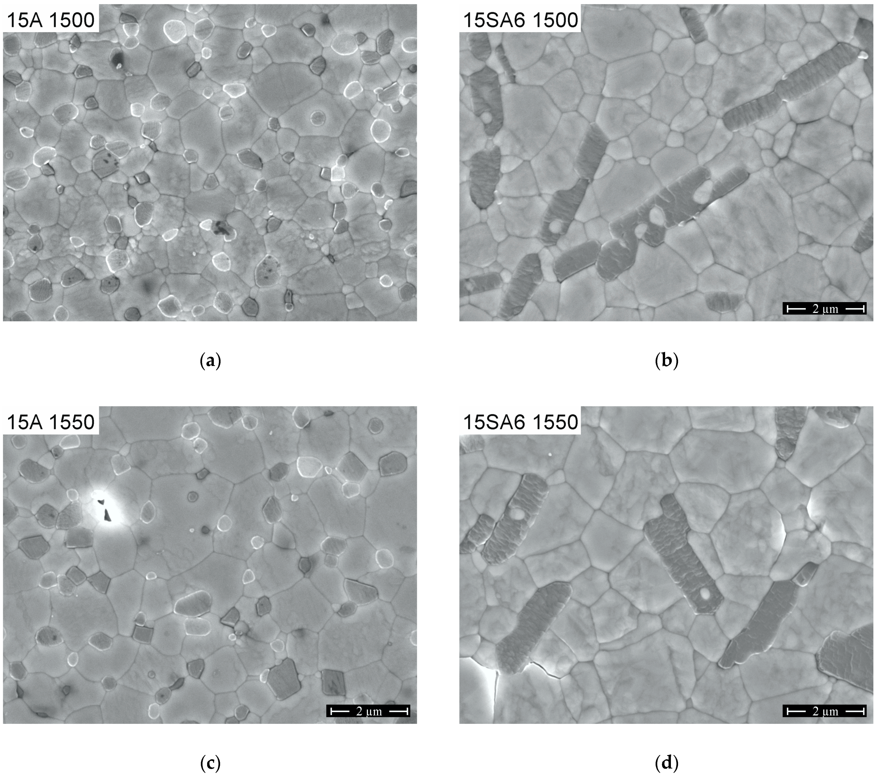
Figure 1. SEM images of polished and thermally etched surfaces of (a) 15A-1500, (b) 15SA6-1500, (c) 15A-1550, and (d) 15SA6-1550.
Applsci 09 00729 g001
Figure 2. SEM images of crack propagation in different composites for: (a) 10A-5SA6-1525, (b) 15SA6-1525, (c) 15SA6-1525 (crack direction always from bottom to top).
Applsci 09 00729 g002
Figure 3. Vickers hardness HV10 depending on composition and sintering temperature.
Applsci 09 00729 g003
Figure 4. Mechanical properties depending on composition and sintering temperature for: (a) Bending strength σ4pt; (b) Fracture resistance KISB.
Applsci 09 00729 g004
Figure 5. Monoclinic phase content of zirconia depending on composition and sintering temperature, measured on: (a) Polished surfaces; (b) Fracture surfaces.
Applsci 09 00729 g005
Figure 6. Low temperature degradation of selected materials.
Applsci 09 00729 g006
Figure 7. Mehl-Avrami-Johnson-Plots for: (a) 15A; (b) 10A-5SA6; (c) 5A-10SA6; (d) 0A-15SA6 composites.
Applsci 09 00729 g007
Table 1. Material compositions and abbreviations.
CompositionAbbreviation
1 mol% Y2O3-6 mol% CeO2-TZP - 15 vol% Al2O3-0 vol%SA615A
1 mol% Y2O3-6 mol% CeO2-TZP - 10 vol% Al2O3-5 vol%SA610A-5SA6
1 mol% Y2O3-6 mol% CeO2-TZP - 5 vol% Al2O3-10 vol%SA65A-10SA6
1 mol% Y2O3-6 mol% CeO2-TZP - 0 vol% Al2O3-15 vol%SA615SA6