Architectural Concept and Evaluation of a Framework for the Efficient Automation of Computational Scientific Workflows: An Energy Systems Analysis Example

 , , ,
, , ,  and
and
Abstract
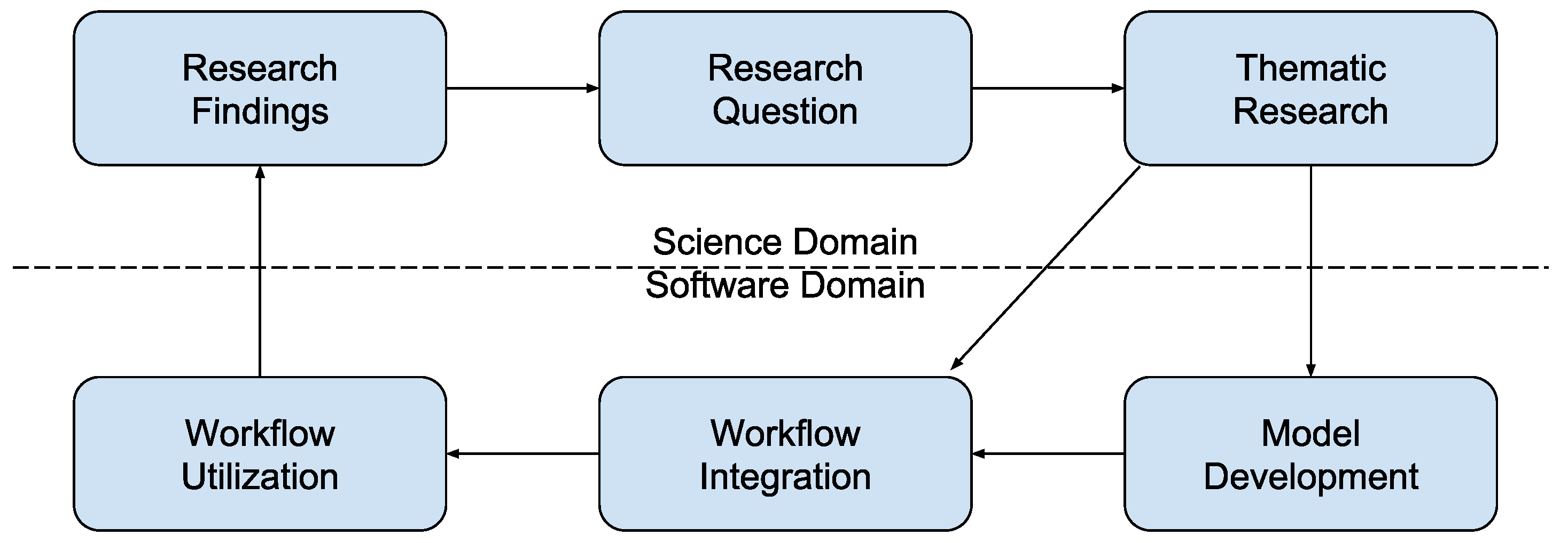
1. Introduction
- automated set up and execution of computational scientific workflows and co-simulations
- reusability of integrated executables with their specific dependencies and runtime environments
- configurable communication between executables without the need for changing executables or specific implementations of interfaces and adapters by the users
- availability of an easy-to-use web interface to build, operate and manage scenarios
- parallelization and coordination of workflows for increasing performance
2. Related Work and State-Of-The-Art Technologies
2.1. Related Work
2.2. State-Of-The-Art Technologies
2.2.1. Microservices-Based Architecture
- increased resilience due to independent development and deployment of services
- fast
- better code quality
- easier debugging and maintenance
- increased productivity
- improved scalability
- freedom (in a way) to choose the implementation technology/language
- continuous delivery
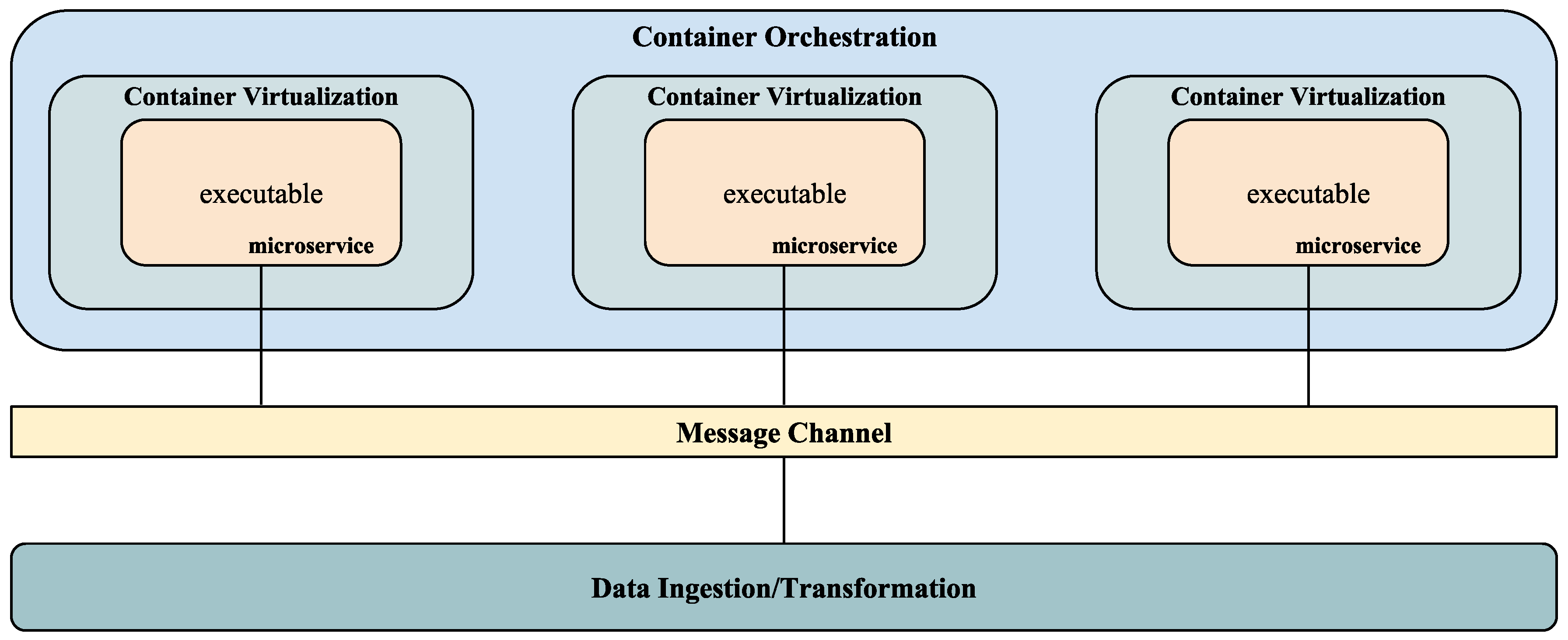
2.2.2. Container Virtualization—Docker
2.2.3. Container Orchestration—Kubernetes
2.2.4. Message Channel—Redis
2.2.5. Data Ingestion/Transformation—Apache NiFi
3. Framework Architecture
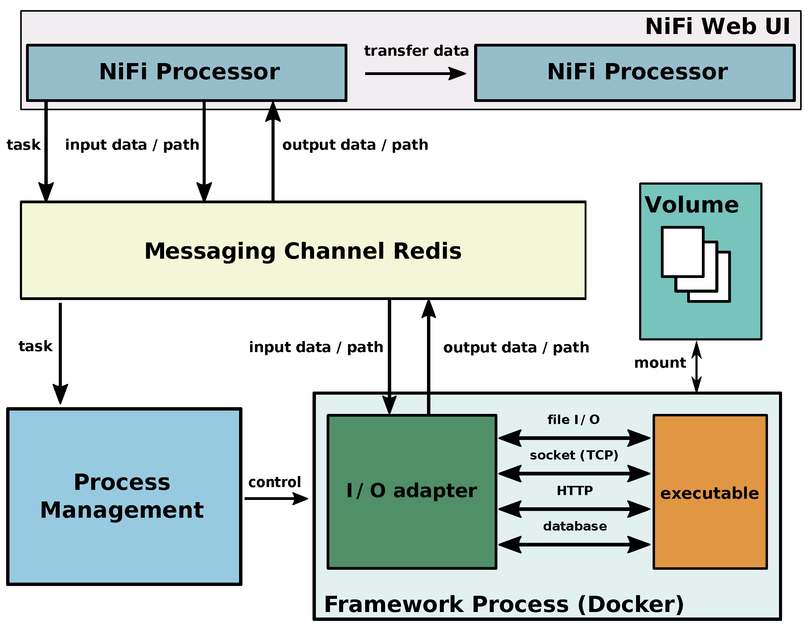
3.1. Apache NiFi User Interface and Processors
3.2. Integrating a Communication and Coordination Infrastructure Using a Message Oriented Middleware
3.3. Process Management
3.4. Framework Processes
3.5. Volume
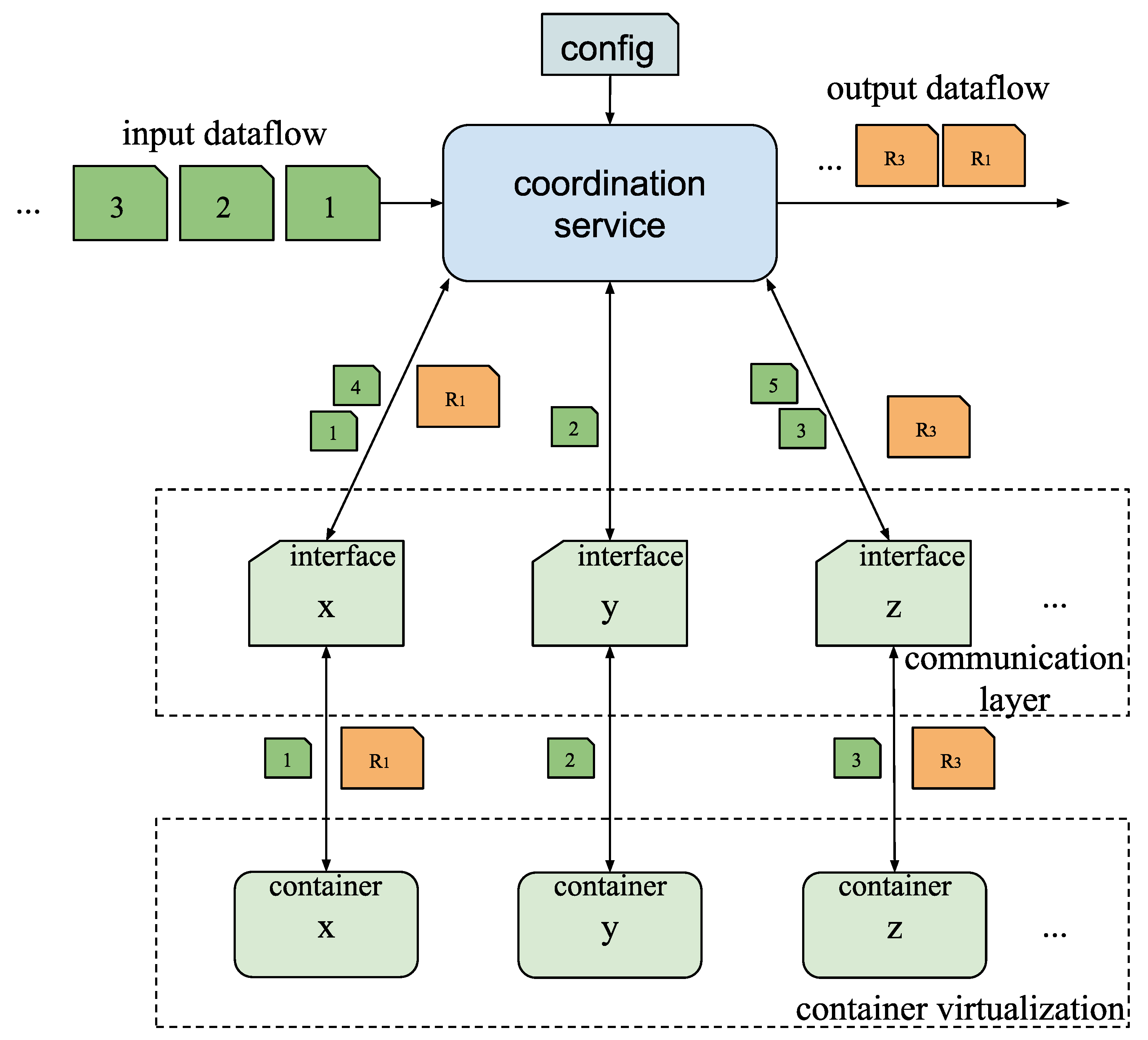
3.6. Parallelization and Synchronization
4. Results
4.1. Benchmarking
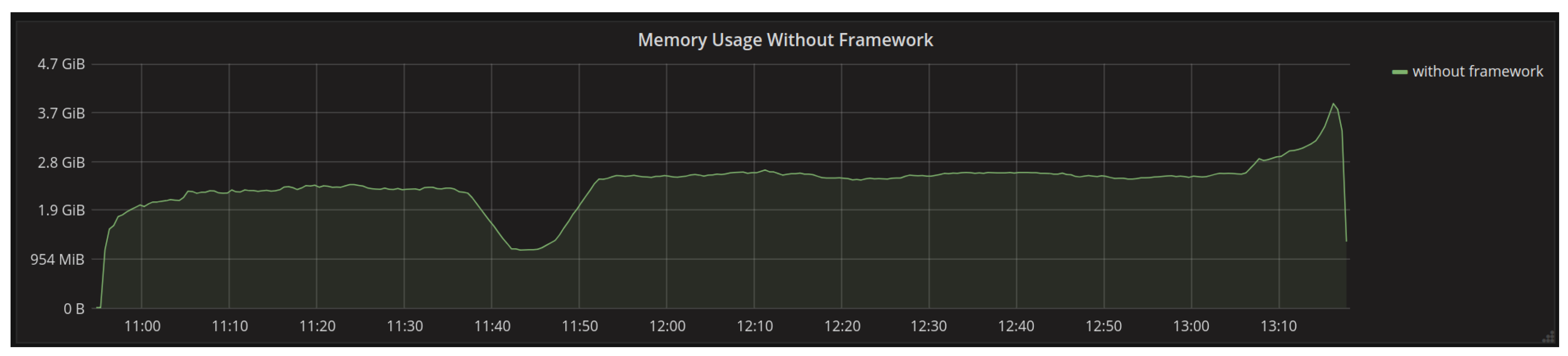
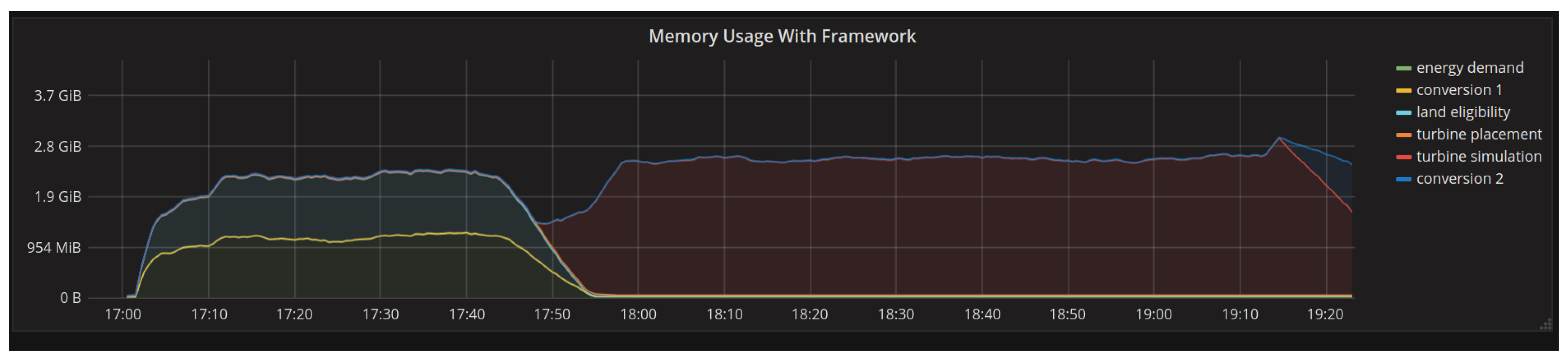
4.1.1. Memory Usage
4.1.2. Execution Time
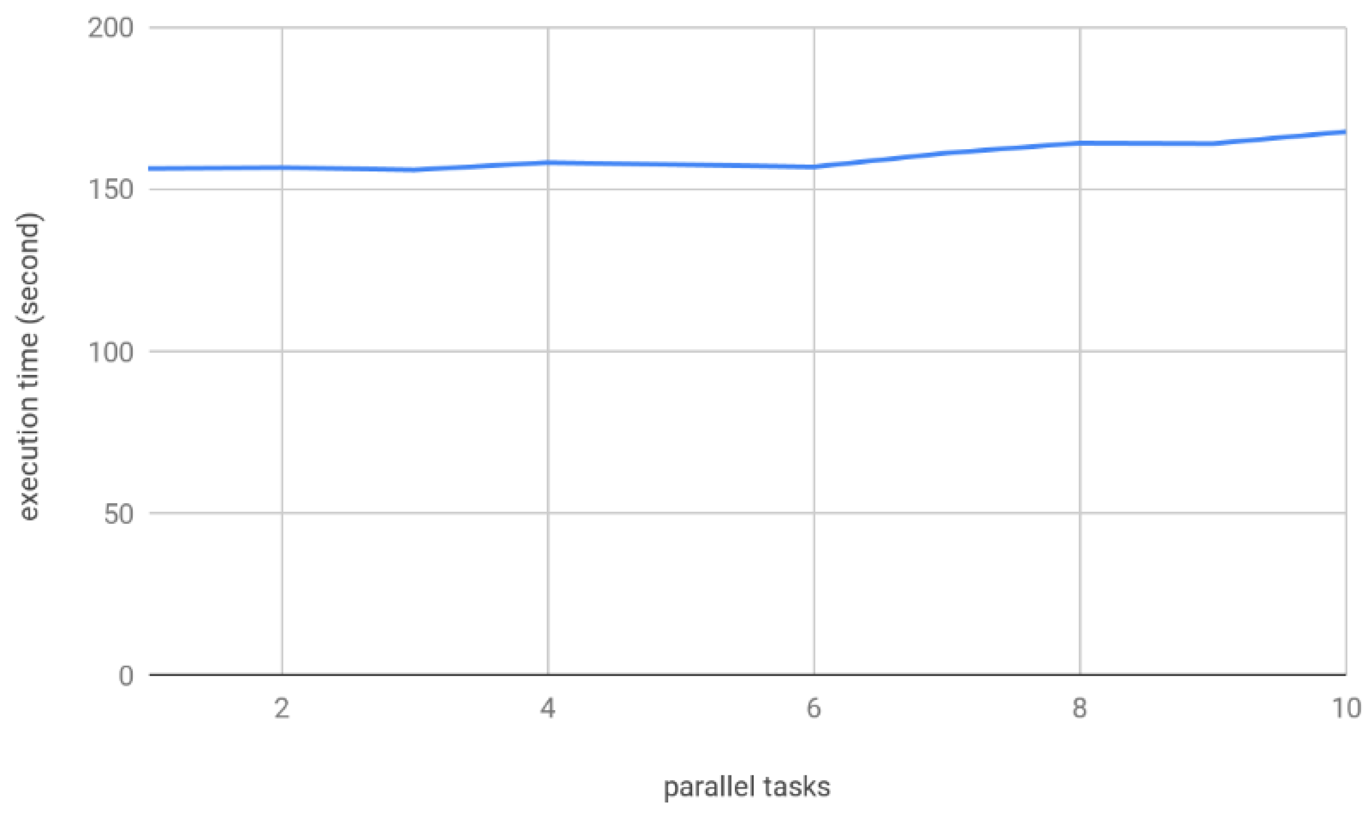
4.1.3. Parallelization
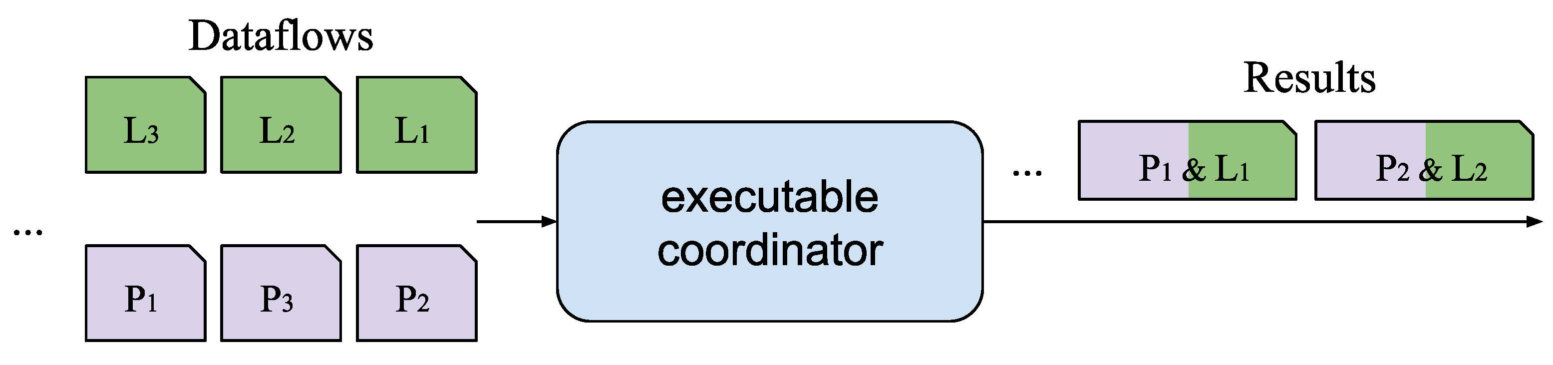
4.2. Evaluation of the Coordination Service for Synchronization of Multiple Inputs
5. Discussion
6. Conclusions
Author Contributions
Acknowledgments
Conflicts of Interest
References
- Rosenzweig, I.; Hodges, B.R. A Python Wrapper for Coupling Hydrodynamic and Oil Spill Models; Center for Research in Water Resources, University of Texas at Austin: Austin, TX, USA, 2011. [Google Scholar]
- Foley, S.S.; Elwasif, W.R.; Bernholdt, D.E. The Integrated Plasma Simulator: A Flexible Python Framework for Coupled Multiphysics Simulation. In PyHPC 2011: Python for High Performance and Scientific Computing; Available as Oak Ridge National Laboratory Technical Report ORNL/TM-2012/57; Oak Ridge National Laboratory: Oak Ridge, TN, USA, 2011. [Google Scholar]
- Andersson, C.; Åkesson, J.; Führer, C. PyFMI: A Python Package for Simulation of Coupled Dynamic Models with the Functional Mock-up Interface; Technical Report in Mathematical Sciences; Centre for Mathematical Sciences, Lund University: Lund, Sweden, 2016; Volume 2016, No. 2. [Google Scholar]
- Blochwitz, T.; Otter, M.; Arnold, M.; Bausch, C.; Clauß, C.; Elmqvist, H.; Junghanns, A.; Mauss, J.; Monteiro, M.; Neidhold, T.; et al. The functional mockup interface for tool independent exchange of simulation models. In Proceedings of the 8th International Modelica Conference, Technical University, Dresden, Germany, 20–22 March 2011; No. [Google Scholar]
- Liu, J.; Braun, E.; Düpmeier, C.; Kuckertz, P.; Ryberg, D.S.; Robinius, M.; Stolten, D.; Hagenmeyer, V. A Generic and Highly Scalable Framework for the Automation and Execution of Scientific Data Processing and Simulation Workflows. In Proceedings of the 2018 IEEE International Conference on Software Architecture (ICSA), Seattle, WA, USA, 30 April–4 May 2018; pp. 145–155. [Google Scholar]
- Naik, N. Docker container-based big data processing system in multiple clouds for everyone. In Proceedings of the 2017 IEEE International Systems Engineering Symposium (ISSE), Vienna, Austria, 11–13 October 2017; pp. 1–7. [Google Scholar]
- Liu, J.; Dupmeier, C.; Hagenmeyer, V. A new concept of a generic co-simulation platform for energy systems modeling. In Proceedings of the FTC 2017—Future Technologies Conference 2017, Vancouver, BC, Canada, 29–30 November 2017; pp. 97–103. [Google Scholar]
- Merkel, D. Docker: Lightweight linux containers for consistent development and deployment. Linux J. 2014, 2014, 239. [Google Scholar]
- Anderson, C. Docker [Software engineering]. IEEE Softw. 2015, 32, 102-c3. [Google Scholar] [CrossRef]
- Sarnovsky, M.; Bednar, P.; Smatana, M. Data integration in scalable data analytics platform for process industries. In Proceedings of the 2017 IEEE 21st International Conference on Intelligent Engineering Systems (INES), Larnaca, Cyprus, 20–23 October 2017; pp. 000187–000192. [Google Scholar]
- Amarasekara, B.; Ranaweera, C.; Nirmalathas, A.; Evans, R. Co-simulation platform for smart grid applications. In Proceedings of the 2015 IEEE Innovative Smart Grid Technologies—Asia (ISGT ASIA), Bangkok, Thailand, 3–6 November 2015; pp. 1–6. [Google Scholar]
- Sun, X.; Chen, Y.; Liu, J.; Huang, S. A co-simulation platform for smart grid considering interaction between information and power systems. In Proceedings of the ISGT 2014, Washington, DC, USA, 19–22 February 2014; pp. 1–6. [Google Scholar]
- Bian, D.; Kuzlu, M.; Pipattanasomporn, M.; Rahmanm, S.; Wu, Y. Real-time co-simulation platform using OPAL-RT and OPNET for analyzing smart grid performance. In Proceedings of the 2015 IEEE Power & Energy Society General Meeting, Denver, CO, USA, 26–30 July 2015; pp. 1–5. [Google Scholar]
- Bhor, D.; Angappan, K.; Sivalingam, K.M. A co-simulation framework for Smart Grid wide-area monitoring networks. In Proceedings of the 2014 Sixth International Conference on Communication Systems and Networks (COMSNETS), Bangalore, India, 7–10 January 2014; pp. 1–8. [Google Scholar]
- Shu, D.; Xie, X.; Jiang, Q.; Guo, G.; Wang, K. A Multirate EMT Co-Simulation of Large AC and MMC-Based MTDC Systems. IEEE Trans. Power Syst. 2018, 33, 1252–1263. [Google Scholar] [CrossRef]
- Schuette, S.; Scherflke, S.; Troeschel, M. Mosaik: A framework for modular simulation of active components in smart grids. In Proceedings of the 2011 IEEE First International Workshop on Smart Grid Modeling and Simulation (SGMS), Brussels, Belgium, 17 October 2011; The Series Lecture Notes in Computer Science. pp. 55–60. [Google Scholar]
- Palensky, P.; Van Der Meer, A.A.; Lopez, C.D.; Joseph, A.; Pan, K. Cosimulation of Intelligent Power Systems: Fundamentals, Software Architecture, Numerics, and Coupling. IEEE Ind. Electron. Mag. 2017, 11, 34–50. [Google Scholar] [CrossRef]
- Schloegl, F.; Rohjans, S.; Lehnhoff, S.; Velasquez, J.; Stein-brink, C.; Palensky, P. Towards a classification scheme for cosimulation approaches in energy systems. In Proceedings of the 2015 International Symposium on Smart Electric Distribution Systems and Technologies (EDST), Vienna, Austria, 8–11 September 2015; pp. 516–521. [Google Scholar]
- Steinbrink, C.; van der Meer, A.A.; Cvetkovic, M.; Babazadeh, D.; Rohjans, S.; Palensky, P.; Lehnhoff, S. Smart Grid Co-Simulation with MOSAIK and HLA: A Comparison Study. Comput. Sci. Res. Dev. 2018, 33, 135. [Google Scholar] [CrossRef]
- Easy-to-Use GUI for Mosaik Available. Available online: https://mosaik.offis.de/2017/06/21/maverig_installation/ (accessed on 3 January 2019).
- Huang, R.; Fan, R.; Daily, J.; Fisher, A.; Fuller, J. Open-source framework for power system transmission and distribution dynamics co-simulation. IET Gener. Transm. Distrib. 2017, 11, 3152–3162. [Google Scholar] [CrossRef]
- Palmintier, B.; Krishnamurthy, D.; Top, P.; Smith, S.; Daily, J.; Fuller, J. Design of the HELICS high-performance transmission-distribution-communication-market co-simulation framework. In Proceedings of the 2017 Workshop on Modeling and Simulation of Cyber-Physical Energy Systems (MSCPES), Pittsburgh, PA, USA, 21 April 2017; pp. 1–6. [Google Scholar]
- Hasselbring, W.; Steinacker, G. Microservice Architectures for Scalability, Agility and Reliability in E-Commerce. In Proceedings of the 2017 IEEE International Conference on Software Architecture Workshops (ICSAW), Gothenburg, Sweden, 5–7 April 2017; pp. 243–246. [Google Scholar]
- Dragoni, N.; Giallorenzo, S.; Lafuente, A.L.; Mazzara, M.; Montesi, F.; Mustafin, R.; Safina, L. Microservices: Yesterday Today and Tomorrow. In Present and Ulterior Software Engineering; Springer: Cham, Switzerland, 2017; pp. 195–216. [Google Scholar]
- Microservices. Available online: https://microservices.io/ (accessed on 3 January 2019).
- Singh, V.; Peddoju, S.K. Container-based microservice architecture for cloud applications. In Proceedings of the 2017 International Conference on Computing, Communication and Automation (ICCCA), Greater Noida, India, 5–6 May 2017; pp. 847–852. [Google Scholar]
- Khazaei, H.; Barna, C.; Beigi-Mohammadi, N.; Litoiu, M. Efficiency Analysis of Provisioning Microservices. In Proceedings of the 2016 IEEE International Conference on Cloud Computing Technology and Science (CloudCom), Luxembourg, 12–15 December 2016; pp. 261–268. [Google Scholar]
- Villamizar, M.; Garcés, O.; Ochoa, L.; Castro, H.; Salamanca, L.; Verano, M.; Casallas, R.; Gil, S.; Valencia, C.; Zambrano, A.; et al. Infrastructure Cost Comparison of Running Web Applications in the Cloud Using AWS Lambda and Monolithic and Microservice Architectures. In Proceedings of the 2016 16th IEEE/ACM International Symposium on Cluster, Cloud and Grid Computing (CCGrid), Cartagena, Colombia, 16–19 May 2016; pp. 179–182. [Google Scholar]
- Amaral, M.; Polo, J.; Carrera, D.; Mohomed, I.; Unuvar, M.; Steinder, M. Performance evaluation of microservices architectures using containers. In Proceedings of the 2015 IEEE 14th International Symposium on Network Computing and Applications (NCA), Cambridge, MA, USA, 28–30 September 2015; pp. 27–34. [Google Scholar]
- Soltesz, S.; Pötzl, H.; Fiuczynski, M.E.; Bavier, A.; Peterson, L. Container-based operating system virtualization: A scalable highperformance alternative to hypervisors. ACM SIGOPS Oper. Syst. Rev. 2007, 41, 275–287. [Google Scholar] [CrossRef]
- Felter, W.; Ferreira, A.; Rajamony, R.; Rubio, J. An updated performance comparison of virtual machines and linux containers. Technology 2014, 28, 32. [Google Scholar]
- Docker. Available online: https://www.docker.com/ (accessed on 3 January 2019).
- Li, Y.; Xia, Y. Auto-scaling web applications in hybrid cloud based on docker. In Proceedings of the 2016 5th International Conference on Computer Science and Network Technology (ICCSNT), Changchun, China, 10–11 December 2016; pp. 75–79. [Google Scholar]
- Kubernetes. Available online: https://kubernetes.io/ (accessed on 3 January 2019).
- Abdollahi Vayghan, L.; Saied, M.A.; Toeroe, M.; Khendek, F. Deploying Microservice Based Applications with Kubernetes: Experiments and Lessons Learned. In Proceedings of the 2018 IEEE 11th International Conference on Cloud Computing (CLOUD), San Francisco, CA, USA, 2–7 July 2018; pp. 970–973. [Google Scholar]
- Modak, A.; Chaudhary, S.D.; Paygude, P.S.; Ldate, S.R. Techniques to Secure Data on Cloud: Docker Swarm or Kubernetes? In Proceedings of the 2018 Second International Conference on Inventive Communication and Computational Technologies (ICICCT), Coimbatore, India, 20–21 April 2018; pp. 7–12. [Google Scholar]
- Docker Swarm. Available online: https://docs.docker.com/engine/swarm/ (accessed on 3 January 2019).
- A Distributed, Reliable Key-Value Store for the Most Critical Data of a Distributed System. Available online: https://coreos.com/etcd/ (accessed on 11 January 2019).
- Goel, L.B.; Majumdar, R. Handling mutual exclusion in a distributed application through Zookeeper. In Proceedings of the 2015 International Conference on Advances in Computer Engineering and Applications, Ghaziabad, India, 19–20 March 2015; pp. 457–460. [Google Scholar]
- Redis. Available online: https://redis.io/ (accessed on 3 January 2019).
- Apache NiFi. Available online: https://nifi.apache.org/ (accessed on 3 January 2019).
- Robinius, M. Strom- und Gasmarktdesign zur Versorgung des Deutschen Strassenverkehrs mit Wasserstoff. Ph.D. Thesis, RWTH Aachen University, Aachen, Germany, 2015. (In German). [Google Scholar]
- Robinius, M.; Otto, A.; Syranidis, K.; Ryberg, D.S.; Heuser, P.; Welder, L.; Grube, T.; Markewitz, P.; Tietze, V.; Stolten, D. Linking the power and transport sectors—Part 2: Modelling a sector coupling for Germany. Energies 2017, 10, 957. [Google Scholar] [CrossRef]
- Ryberg, D.S.; Robinius, M.; Stolten, D. Evaluating Land Eligibility Constraints of Renewable Energy Sources in Europe. Energies 2018, 11, 1246. [Google Scholar] [CrossRef]
- Geospatial Land Availability for Energy Systems (GLAES). Available online: https://github.com/FZJ-IEK3-VSA/glaes (accessed on 4 January 2019).
- Ryberg, D.S.; Caglayan, D.G.; Schmitt, S.; Linßen, J.; Stolten, D.; Robinius, M. The Future of European Onshore Wind Energy Potential: Detailed Distribution and Simulation of Advanced Turbine Designs. Preprints 2018, 2018120196. [Google Scholar] [CrossRef]
- Welder, L.; Ryberg, D.S.; Kotzur, L.; Grube, T.; Robinius, M.; Stolten, D. Spatio-temporal optimization of a future energy system for power-to-hydrogen applications in Germany. Energy 2018, 158. [Google Scholar] [CrossRef]


| Framework Requirements | Apache Kafka | Redis |
|---|---|---|
| fast storage | in-memory and disk-based | in-memory |
| a database and a message broker | a message service | can be used as a database, cache, and message broker |
| short lived messages | can keep flushing data for longer period of time | retain data for short period of time |
| small amount of data | large data size | small data size |
| Model | Manual Execution Time (s) | Execution Time with Framework (s) |
|---|---|---|
| land eligibility | 30.895 | 31.614 |
| turbine placement | 5.245 | 5.147 |
| turbine simulation | 180.357 | 178.956 |
| conversion 2 | 22.406 | 23.874 |
| energy demand | 30.988 | 30.615 |
| conversion 1 | 0.504 | 0.517 |
| all models | 238.903 | 239.591 |
© 2019 by the authors. Licensee MDPI, Basel, Switzerland. This article is an open access article distributed under the terms and conditions of the Creative Commons Attribution (CC BY) license (http://creativecommons.org/licenses/by/4.0/).
Share and Cite
Liu, J.; Braun, E.; Düpmeier, C.; Kuckertz, P.; Ryberg, D.S.; Robinius, M.; Stolten, D.; Hagenmeyer, V. Architectural Concept and Evaluation of a Framework for the Efficient Automation of Computational Scientific Workflows: An Energy Systems Analysis Example. Appl. Sci. 2019, 9, 728. https://doi.org/10.3390/app9040728
Liu J, Braun E, Düpmeier C, Kuckertz P, Ryberg DS, Robinius M, Stolten D, Hagenmeyer V. Architectural Concept and Evaluation of a Framework for the Efficient Automation of Computational Scientific Workflows: An Energy Systems Analysis Example. Applied Sciences. 2019; 9(4):728. https://doi.org/10.3390/app9040728
Chicago/Turabian StyleLiu, Jianlei, Eric Braun, Clemens Düpmeier, Patrick Kuckertz, D. Severin Ryberg, Martin Robinius, Detlef Stolten, and Veit Hagenmeyer. 2019. "Architectural Concept and Evaluation of a Framework for the Efficient Automation of Computational Scientific Workflows: An Energy Systems Analysis Example" Applied Sciences 9, no. 4: 728. https://doi.org/10.3390/app9040728
APA StyleLiu, J., Braun, E., Düpmeier, C., Kuckertz, P., Ryberg, D. S., Robinius, M., Stolten, D., & Hagenmeyer, V. (2019). Architectural Concept and Evaluation of a Framework for the Efficient Automation of Computational Scientific Workflows: An Energy Systems Analysis Example. Applied Sciences, 9(4), 728. https://doi.org/10.3390/app9040728