Article

Design of a Liquid-Crystal-Tunable Terahertz Demultiplexer Based on a Metal-Insulator-Metal Waveguide

1
School of Automation, Guangdong University of Technology, Guangzhou 510006, China
2
College of Electronic Science and Technology, Shenzhen University, Shenzhen 518060, China
3
Institute of Electronic Paper Displays, South China Academy of Advanced Optoelectronics, South China Normal University, Guangzhou 510631, China
4
Department of Electrical and Computer Engineering, Duke University, Durham, NC 27708, USA
*
Author to whom correspondence should be addressed.
Appl. Sci. 2019, 9(4), 644; https://doi.org/10.3390/app9040644
Submission received: 25 December 2018 / Revised: 11 February 2019 / Accepted: 11 February 2019 / Published: 14 February 2019

Abstract

:
A tunable demultiplexer with three output channels infiltrated by liquid crystal (LC) is presented, which is based on a metal-insulator-metal (MIM) waveguide. The operating frequencies of the three output channels can be tuned simultaneously at will by changing the external bias electric field applied to the LC. By analyzing the Fabry-Pérot (FP) resonance modes of the finite-length MIM waveguide both theoretically and numerically, the locations of the three channels are delicately determined to achieve the best demultiplexing effects. Terahertz (THz) signals input from the main channel can be demultiplexed by channels 1, 2 and 3 at 0.7135 THz, 1.068 THz and 1.429 THz, respectively. By applying an external electric field to alter the tilt angle of the infiltrating LC material, the operating frequencies of channels 1, 2 and 3 can be relatively shifted up to 12.3%, 9.6% and 9.7%, respectively. The designed demultiplexer can not only provide a flexible means to demultiplex signals but also tune operating bands of output channels at the same time.

1. Introduction

Demultiplexing technology is employed to convert a signal containing multiple signal streams back into the original separate and unrelated signals. Demultiplexer in the terahertz range is under active development nowadays [1,2]. In this frequency range, lots of devices, like switches, modulators, sensors, etc., have emerged in recent years to facilitate ultra-wideband communications [3,4,5].
However, the rapid development of communication systems is always short of devices that can match their evolving performance requirements. Therefore, tunable materials are playing a key role in developing optic-electric devices that are flexible and easy to use. Graphene is widely used in adjustable devices owing to the diversity of its tunable parameters [6,7,8]. With adjustable permeability by magnetic fields, ferrite is also attractive for devices in the terahertz or optical range [9,10,11]. Since the liquid crystal (LC) is fluid, it is better used for volume devices, like waveguides [12], or flexible components, like wearable filters [13].
In recent years, nematic liquid crystals (NLCs) have been widely used in tunable optic-electric devices, because the optical axis of NLC molecules can be controlled by an external electric field or a magnetic field. The NLC’s controllable dielectric properties, wide range of operating frequencies and multiple ways of being adjusted are attractive for design tunable devices [14,15]. In the gigahertz band, LC has been tailored in a filter or amplifier to adjust their operating bands [16,17]. In the optical band, LC has found its usage in switches, sensors, waveplates, etc. [18,19,20]. Recently, there has been growing interest in utilizing the LC for devices working in the terahertz range [21,22,23]. In addition to the extension of the applied frequencies using the LC, ways to adjust the LC are also diversified. Electrical control of the tilt angle of the LC is a prevailing method because it can be fully used as a tunable medium for convenience and effectiveness [24,25]. By applying an external magnetic field, dielectric parameters of the LC can also be adjusted without any direct contact with the devices employing it [26,27]. The temperature stability of the LC is always required to keep the devices operating effectively. The temperature sensitivity of the LC can also be used to change its properties to realize tunable devices, even though its temperature response is relatively slow [28,29].
Among various devices that achieve tunability by using the LC, metal-insulator-metal (MIM) and insulator-metal-insulator (IMI) waveguides are preferable as the infrastructure due to their simplicity and effectiveness. This is because the metal plates forming these waveguides are well suited to applying a bias voltage to adjust the tilt angle of the LC infiltrated in the waveguide. For example, some recently devised tunable optical resonators and switches are based on the prototype of the LC-infiltrated MIM waveguides [30,31]. As a cladding material of IMI waveguides, the LC has also found its application in surface plasmon polaritons (SPP) filters or transmission devices [32,33]. Considering the advantages of the MIM waveguide, it is also preferred as the infrastructure of the demultiplexer presented here.
In this paper, we present an LC-infiltrated tunable demultiplexer with multiple slots as output channels, which is biased by an external electric field (E). The propagating property of a MIM waveguide is closely related to dielectric parameters of the intermediate layer sandwiched by two metal layers. Thus, employing LC as the infiltrating material of the MIM waveguide can provide an efficient method of tuning the transmission characteristics of the waveguide. Meanwhile, etching slots on a metal plate of the MIM waveguide introduces multiple output channels of the device. To determine the optimistic locations of the output channels, the field distribution of Fabry-Pérot (FP) resonances of the finite-length MIM waveguide is theoretically and numerically investigated. Thus, the demultiplexing effects of the devices can be tuned by changing an external bias electric field that can adjust the tilt angle of the LC infiltrated in the MIM waveguide. Such a device in micrometer scale can provide an effective and flexible way of demultiplexing signals in the terahertz range.

2. Theoretical Basis

In the terahertz frequency range, LC can be treated as a lossy and dispersive media [23,34]. We employ the polynomial model to fit the refractive index (n) and absorption coefficient (α) of E7, which is used as the LC material throughout the paper. As for the dielectric properties of E7, it has a positive dielectric anisotropy (Δε > 0). The ordinary refractive index (no) and extraordinary refractive index (ne) of E7 are 1.56 and 1.70, respectively, at the operating frequency of 1 THz and temperature of 26 °C [35,36]. With the electric field E > 7 kV/m, the E7 reaches a maximum value that is the extraordinary refractive index (ne) of 1.70. The refractive index of E7 is a value that can be controlled between 1.56 and 1.70, depending on the external electric field. Its dielectric properties have been studied experimentally in reference [35]. Fitting the dielectric properties of E7 in the terahertz range by the polynomial model, the lossy and dispersive characteristics of the LC presented in this paper would be accurate and reasonable. The polynomial model is employed and shown below:
n E ( ω ) = i = 0 M n k i , E ω i
α E ( ω ) = i = 0 M α h i , E ω i
where n E and α E are the refractive index and absorption coefficient of the LC under the bias electric field E, respectively; Mn and Mα are the order of the polynomials for n E and α E , respectively; ki,E and hi,E stand for the coefficients in the fitted polynomials for the refractive index and absorption coefficient, respectively. Owing to the simplicity and effectiveness of the polynomial model, it was chosen to model the dielectric properties of E7 in the terahertz range. Figure 1 presents our fitted results based on Equations (1) and (2) (Mn = 5, Mα = 16), which are in good agreement with the experimental ones in reference [35]. Throughout the paper, the bias electric field of the LC is selected from 0 kV/m, 3 kV/m, 5 kV/m or 7 kV/m, which can tune the dielectric properties of the LC. The external electric field is set in the range of 0 to 7 kV/m, since when E > 7 kV/m the refractive index of E7 has already reached the maximum value that is the extraordinary refractive index (ne = 1.70) [35]. Due to the numerous parameters in the polynomial fit, the fitting parameters of E7 with order Mn equals to 5 and Mα equals to 16 are listed in Table A1 and Table A2 of Appendix A.
Sandwiched by the upper and lower metal plates, the main channel forms a planar waveguide where electromagnetic (EM) waves propagate. Figure 2 shows the schematic of the MIM waveguide.
Across the upper and lower metal plates, a voltage is applied to tune the dielectric properties of the LC. The voltage induces an electric field in the main channel and tilts the LC molecules, thereby changing the dielectric properties of the LC. When the strength of the electric field applied to the main channel varies, the main body of the LC molecules tends to tilt with different angles, leading to different permittivities of the LC and hence different propagation characteristics of EM waves in the main channel.
Under the geometry shown in Figure 2, the TM mode dominates in the MIM waveguide. The propagation constant of a planar waveguide is determined by the width of the main channel as well as the dielectric property of the LC and metal forming the channel. Taking the dielectric property of the LC into consideration, the dispersion relation of the planar waveguide can be obtained as follows [37]:
tanh ( k 1 W 2 ) = k 2 ε 1 k 1 ε 2
k i 2 = k z 2 k 0 2 ε i , i = 1 , 2
where kz is the propagation constant of EM waves in the z direction; k1 and k2 are the wave number in the LC and metal in the x direction, respectively; k0 is the wave number in the free space; ε1 and ε2 are the relative permittivities of LC and metal, respectively. The relative permittivity of LC can be obtained using its refractive index n and absorption coefficient α by the following equation:
ε 1 = ( n j α c 4 π f ) 2
Meanwhile, copper is used as the metal in our device throughout the paper. In order to express the properties of copper accurately, its relative permittivity is given by the Drude model:
ε 2 = ε ω p 2 ω 2 j γ ω
where ωp and γ are the plasma frequency and collision frequency of copper, respectively, and ε stands for the dielectric constant at infinite frequency. For copper in the terahertz range, ωp, γ and ε are set to 1.123 × 10¹⁶ rad/s, 2.196 × 10¹² Hz and 1, respectively [38].
By numerical computation, the dispersion curves of the LC-infiltrated planar waveguide are shown in Figure 3, where the geometry of the waveguide is L = 240 µm and W = 5 µm. The propagation constant is normalized in terms of kunit = 2π/L. Figure 3 shows that the propagation constant can be changed with different bias electric fields of the LC. For a fixed frequency, the propagation constant is larger with a higher bias electric field.
The limited length of the MIM waveguide will induce reflections that lead to the so-called FP resonance and thus multiple peaks in the transmission spectrum. The resonance in the transmission spectrum should follow the FP cavity resonant condition [39]:
k z L = m π
where kz is the propagation constant along the main channel of the MIM waveguide, L is the longitudinal length of the waveguide, and m = 1, 2, 3,…, ∞ is the order of the FP mode. By representing kz by 2π/λ in Equation (7), where λ can be substituted by c / ( f Re { n e f f } ) , the FP resonant frequencies of mode m can be expressed as:
f F P , m = m π c 2 π Re { n e f f } L
where Re { n e f f } is the real part of the effective refractive index seen by EM waves propagating along the MIM waveguide.

3. Analysis and Results

In order to study the transmission spectrum and field distribution of the LC-infiltrated device, the finite element method based commercial software, COMSOL Multiphysics, is adopted in our simulations throughout the paper. It is capable of handling dispersive media and is thus suitable for the full-wave simulation of the LC-based devices. The dielectric properties of LC, which is fitted by Equations (1), (2) and (5) under different bias electric fields, can be described by using COMSOL, and then the performance of LC-based devices can be analyzed in the terahertz range.
To start the numerical simulation of the demultiplexer, the geometry of the main channel is chosen to be L = 240 µm, W = 5 µm, as shown in Figure 2. Copper is chosen as the metal surrounding the main channel where the LC material of E7 is infiltrated.

3.1. MIM Waveguide with Only the Main Channel

In the first place, an MIM waveguide with the main channel infiltrated by the LC is investigated. Thus, the FP effect on resonance frequencies of the MIM waveguide can be verified. In addition, different voltages are applied to change the dielectric properties of the LC and investigate their influence on the resonance.
With different bias electric fields of the LC, the transmission spectra of the MIM waveguide are simulated and shown in Figure 4.
In case the bias electric field of the LC equals zero, there are four resonant frequencies at 0.3553 THz, 0.7098 THz, 1.067 THz and 1.425 THz, corresponding to modes 1, 2, 3 and 4, respectively. While the bias electric field is increasing, the resonances of different modes are all shifted to lower frequencies. This is due to the increase of the effective refractive index neff seen by EM waves propagating along the MIM waveguide. Since Figure 3 shows that a larger bias electric field will lead to a larger kz, based on a well-known kz = ω/c neff, the larger kz of the MIM waveguide means the larger neff seen by the propagating EM waves. Consequently, under a larger bias electric field, the fFP,m of the MIM waveguide governed by Equation (8) has a trend of shifting to lower frequencies. Such a phenomenon can be used for a tunable filter by controlling the bias electric field of the LC, if there is just one main channel in the MIM waveguide.
In order to inspect the field distribution under different modes, their normalized Hy field strength in the xoz plane with zero-biased electric field of the LC is presented in Figure 5. Due to the intrinsic characteristic of FP resonance depicted in Equation (7), the number of periods of the field distribution is the same as the mode number m. In fact, the peak field distribution of mode m under resonance is identical under different bias electric fields of the LC, which depends only on the geometry of the resonator. The demanded resonance of the mode m can be easily achieved by setting the MIM waveguide to operate under its m-th resonant frequency, which is given by Equation (8). From Figure 5, it can be seen that the maximum field of mode m appears at the z-coordinate of pm, which can be expressed by:
p m = ( n + 1 2 ) L m
where L/m stands for the period length of the mode m, and n = 0, 1, 2,…, m-1 is the number of periods in front of the peak field.

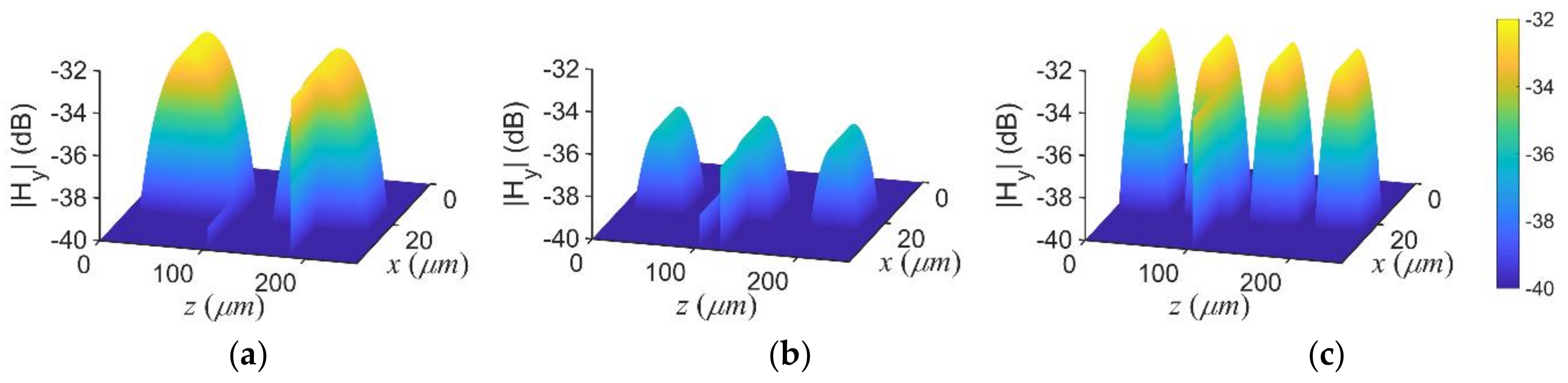
3.2. Demultiplexer Formed by the MIM Waveguide with Multiple Output Channels

With a bias voltage capable of tuning the transmission spectrum of an LC-infiltrated MIM waveguide, it is feasible to design a reconfigurable demultiplexer based on the MIM waveguide as long as its multiple output channels are properly designed. To achieve this, we need to make use of the variation of resonant frequencies of the LC-infiltrated waveguide owing to the change of the bias electric field of the LC. In Section 3.1, we concluded that under different bias electric fields of the LC, the field distributions of the mode m can be the same given that the operating frequency satisfies Equation (8). Therefore, the location of the output channel corresponding to the m-th mode can be chosen to be the location where the mode m has a peak field distribution. By allocating the output channel at this location, the maximum field will exist here when the operating frequency of the MIM waveguide satisfies Equation (8). Thus, the spectrum of the output channel set at this location will have a peak at the frequency fFP,m corresponding to the resonant frequency of the m-th mode. Moreover, by adjusting the bias electric field, the frequency of the spectral peak of the output channel can be changed. Therefore, the passband of the output channel can be tuned by the bias electric field of the LC. Following the same principle, multiple output channels on the MIM waveguide can be set. Their passbands can be controlled simultaneously by adjusting the bias electric field of the LC, ultimately forming a tunable demultiplexer with multiple output channels.
According to the above analysis, the output-channel location should be set at the positions where the maximum field of the mode m occurs. It is worth noting that the number of output channels is set to three to avoid too small intervals between them and prevent unwanted mutual couplings. Figure 6 shows the allocation of the output channels of the MIM waveguide whose dimension is the same as that shown in Figure 2. With three output channels etched on the upper copper plate, the voltage is applied between the four segments of the upper copper plate and the lower copper plate.
Here, three output channels corresponding to modes 2, 3 and 4 are deployed. Their coordinates along the z axis are set to 179 µm, 120 µm and 99 µm, respectively. According to the resonant frequencies from low to high, the ports at 179 µm, 120 µm and 99 µm are named channels 1, 2 and 3, respectively. In order to minimize the cross talk between these output channels, the locations of output channels have been chosen delicately. In this way, the amplitude of transmission spectrum obtained by one output channel can be maximized at its resonant frequency while those of other output channels are minimized as much as possible. Following this criterion, the values of n in Equation (9) are all set to 1 for channel 1, 2 and 3 (or mode 2, 3 and 4). Then, the locations of the channels are meticulously tuned according to multiple simulations. Finally, the coordinates of the output channels 1, 2 and 3 along the z axis were optimized to be 179 µm, 120 µm and 99 µm, respectively. For the output channels, they have the same width D that equals 0.25 µm, which is much smaller than the width of the main channel. It should be noted that the voltage across the sidewalls of all output channels are zero. However, since the output channels are much narrower compared to the main channel, those channels infiltrated with the zero-biased LC have little effect on the field distribution of the main channel.
By numerical simulation of the field distribution in the demultiplexer, the spectra of the three output channels are obtained and shown in Figure 7. With the bias electric field applied, the LC with changed refractive index in the channels in the MIM waveguide shifts the resonant frequencies of all output channels obviously. Figure 7 shows the effects of the bias electric field on the spectra of the output channels. In Figure 7a, for example, the resonant frequency of channel 1 is successfully shifted from 0.7315 THz to 0.6414 THz when the bias electric field changes from 0 kV/m to 7 kV/m. The elaborated effects of the bias electric field of the LC on the spectra of the output channels are listed in Table 1. It can be concluded that the larger bias electric field of the LC shifts the resonant frequencies of all output channels to the lower resonant frequencies, resulting in a tunable demultiplexer. This is because, when a higher bias electric field is applied, the effective refractive index, neff, of the MIM waveguide is larger, which can be deduced from kz = ω/c neff and Figure 3. Consequently, the resonant frequencies governed by Equation (8) can be shifted to lower values due to the larger neff. It should be noted that, although the dimensions of the main and output channels of the demultiplexer are well below the wavelength of the terahertz wave, a fraction of signals can still be transmitted and demultiplexed. Previous research on the LC-infiltrated FP resonator-based filter experimentally showed that around 20% of terahertz signals could be filtered and outputted, where the channel dimension was well below the operating wavelength [40].
Figure 8 shows the |Hy| distributions of the output channels as well as the main channel in dB scale. For the sake of intuitive and clarity, the intensity of |Hy| field in Figure 8 is represented by height as well as color. The demultiplexing effect can be observed from Figure 8. Taking channel 1 at the z coordinate of 179 µm as an example, the field amplitude in the output channel 1 is higher at 0.7315 THz, as shown in Figure 8a, compared to those at 1.068 THz and 1.429 THz, as shown in Figure 8b,c respectively. Other output channels can also have a peak amplitude of fields at its corresponding resonant frequencies, thus rendering a good demultiplexing effect. Because different bias electric fields of the LC still lead to the identical peak location of the m-th resonant mode, Figure 8 just reflects the field distribution with zero-biased electric field of the LC. It should be noted that the absolute amplitude of Hy field at 1.068 THz is relatively smaller than those at other frequencies in Figure 8. This is because the actual field response of the MIM waveguide at different frequencies may vary.

4. Conclusions

This paper has presented a demultiplexer tunable in the terahertz range with three output channels designed on an MIM waveguide incorporating the LC. Based on the FP resonance of the MIM waveguide and the field distribution under different resonant modes, the operating modes as well as the locations of the three channels can be determined. By applying an external electric field across the copper plates of the MIM waveguide, the dielectric property of the LC infiltrated in the main channel of the MIM waveguide can be changed, and thus the demultiplexer can be tunable. Numerical simulations demonstrate that channels 1, 2 and 3 can demultiplex signals from the main channel at frequencies of 0.7315 THz, 1.068 THz and 1.429 THz, respectively. By applying electric field from 0 kV/cm to 7 kV/cm on the MIM waveguide, the operating frequencies of the output channels 1, 2 and 3 can be shifted relatively as large as 12.3%, 9.6% and 9.7%, respectively. Such an LC-infiltrated MIM waveguide with output channels can achieve desired demultiplexing results in the terahertz range. The demultiplexer presented here is also a meaningful reference for demultiplexing signals in the optical and microwave ranges, because the tunability of the LC material is still valid in those frequency ranges.

Author Contributions

X.-S.L. conceived the idea, analyzed the data, and wrote the paper. N.F. revised the manuscript and supervised the whole work. Y.-M.X. analyzed the simulations and revised the manuscript. L.-L.C. and Q.H.L. provided suggestions and revised the manuscript.

Funding

This work was supported by the National Natural Science Foundation of China (61505035, 11734012, 11574218), the China Scholarship Council, the National Key Research and Development Plan (2016YFB1200402-019), and the Guangdong Science and Technology Plan (2015B090923004).

Conflicts of Interest

The authors declare no conflict of interest.

Appendix A

Table A1. Polynomial fitting of the refractive index of E7.
ParametersE = 0 kV/mE = 3 kV/mE = 5 kV/mE = 7 kV/m
k0,01.611.641.671.69
k1,01.51 × 10−13.48 × 10−21.18 × 10−22.35 × 10⁻²
k2,0−3.66 × 10⁻¹−8.00 × 10⁻²−2.48 × 10⁻²−7.55 × 10⁻³
k3,03.05 × 10−13.85 × 10−25.59 × 10−3−2.53 × 10⁻²
k4,0−1.06 × 10⁻¹−1.54 × 10−35.00 × 10−31.93 × 10⁻²
k5,01.34 × 10−2−1.45 × 10⁻³−1.66 × 10⁻³−3.73 × 10⁻³
Table A2. Polynomial fitting of the absorption coefficient of E7.
ParametersE = 0 kV/mE = 3 kV/mE = 5 kV/mE = 7 kV/m
h0,07.50 × 1013.51 × 1022.11 × 102−2.38 × 101
h1,0−2.29 × 10³−8.81 × 10³−5.41 × 1033.37 × 102
h2,02.92 × 1049.56 × 1045.96 × 104−1.29 × 10³
h3,0−2.09 × 10⁵−5.96 × 10⁵−3.75 × 10⁵−4.85 × 10³
h4,09.38 × 1052.39 × 1061.52 × 1066.04 × 104
h5,0−2.83 × 10⁶−6.59 × 10⁶−4.17 × 10⁶−2.46 × 10⁵
h6,05.98 × 1061.29 × 1078.12 × 1065.79 × 105
h7,0−9.10 × 10⁶−1.84 × 10⁷−1.15 × 10⁷−8.94 × 10⁵
h8,01.02 × 1071.94 × 1071.19 × 1079.62 × 105
h9,0−8.43 × 10⁶−1.54 × 10⁷−9.25 × 10⁶−7.42 × 10⁵
h10,05.20 × 1069.09 × 1065.34 × 1064.16 × 105
h11,0−2.38 × 10⁶−4.00 × 10⁶−2.28 × 10⁶−1.69 × 10⁵
h12,07.95 × 1051.29 × 1067.09 × 1054.94 × 104
h13,0−1.88 × 10⁵−2.96 × 10⁵−1.55 × 10⁵−1.01 × 10⁴
h14,03.00 × 1044.56 × 1042.27 × 1041.35 × 103
h15,0−2.87 × 10³−4.24 × 10³−1.97 × 10³−1.07 × 10²
h16,01.25 × 1021.79 × 1027.68 × 1013.74

References

  1. Ma, J.J.; Karl, N.J.; Bretin, S.; Ducournau, G.; Mittleman, D.M. Frequency-division multiplexer and demultiplexer for terahertz wireless links. Nat. Commun. 2017, 8, 729. [Google Scholar] [CrossRef] [PubMed] [Green Version]
  2. Li, S.P.; Liu, H.J.; Sun, Q.B.; Huang, N. Multi-channel terahertz wavelength division demultiplexer with defects-coupled photonic crystal waveguide. J. Mod. Opt. 2016, 63, 955–960. [Google Scholar] [CrossRef]
  3. Zhang, X.L.; Wang, X.B.; Chan, C.T. Switching terahertz waves using exceptional points. Phys. Rev. Appl. 2018, 10, 034045. [Google Scholar] [CrossRef]
  4. Li, S.H.; Li, J.S. Terahertz modulator a using CsPbBr3 perovskite quantum dots heterostructure. Appl. Phys. B Lasers Opt. 2018, 124, 224. [Google Scholar]
  5. Tang, P.R.; Li, J.; Du, L.H.; Liu, Q.; Peng, Q.X.; Zhao, J.H.; Zhu, B.; Li, Z.R.; Zhu, L.G. Ultrasensitive specific terahertz sensor based on tunable plasmon induced transparency of a graphene micro-ribbon array structure. Opt. Express 2018, 26, 30655–30666. [Google Scholar] [CrossRef]
  6. Biabanifard, S.; Biabanifard, M.; Asgari, S.; Asadi, S.; Yagoub, M.C.E. Tunable ultra-wideband terahertz absorber based on graphene disks and ribbons. Opt. Commun. 2018, 427, 418–425. [Google Scholar] [CrossRef]
  7. Wang, W.; Yang, D.X.; Qian, Z.H.; Xu, C.S.; Wang, C. Tunable terahertz band-stop filter based on self-gated graphene monolayers with antidot arrays. Opt. Commun. 2018, 427, 21–26. [Google Scholar] [CrossRef]
  8. Wang, J.G.; Lin, W.H.; Xu, X.F.; Ma, F.C.; Sun, M.T. Plasmon-exciton coupling interaction for surface catalytic reactions. Chem. Rec. 2018, 18, 481–490. [Google Scholar] [CrossRef]
  9. Lai, W.E.; Abdulmunem, O.M.; del Pino, P.; Pelaz, B.; Parak, W.J.; Zhang, Q.; Zhang, H.W. Enhanced terahertz radiation generation of photoconductive antennas based on manganese ferrite nanoparticles. Sci. Rep. 2017, 7, 46261. [Google Scholar] [CrossRef]
  10. Hou, Y.; Fan, F.; Wang, X.H.; Chang, S.J. Terahertz power splitter based on ferrite photonic crystal. Optik 2013, 124, 5285–5288. [Google Scholar] [CrossRef]
  11. Xu, Y.M.; Zhang, H.Y.; Li, X.S.; Wu, Q.B.; Wang, W.G.; Li, Z.H.; Li, J.L. Investigation of the improved performance with ferrites in TiO2 dye-sensitized solar cell. Appl. Surf. Sci. 2017, 424, 245–250. [Google Scholar] [CrossRef]
  12. Armand, H.; Ardakani, M.D. Theoretical study of liquid crystal dielectric-loaded plasmonic waveguide. Int. J. Microw. Wirel. Technol. 2017, 9, 275–280. [Google Scholar] [CrossRef]
  13. Zhao, M.J.; Zhang, Y. Compact wearable 5-GHz flexible filter. Electron. Lett. 2017, 53, 661–662. [Google Scholar] [CrossRef]
  14. Tiwari, A.K.; Pattelli, L.; Torre, R.; Wiersma, D.S. Remote control of liquid crystal elastomer random laser using external stimuli. Appl. Phys. Lett. 2018, 113, 013701. [Google Scholar] [CrossRef]
  15. Fernandez, R.; Gallego, S.; Marquez, A.; Frances, J.; Martinez, F.J.; Pascual, I.; Belendez, A. Analysis of holographic polymer-dispersed liquid crystals (HPDLCs) for tunable low frequency diffractive optical elements recording. Opt. Mater. 2018, 76, 295–301. [Google Scholar] [CrossRef]
  16. Li, X.; Jiang, D.; Yu, H.F. Electrical biasing substrate integrated waveguide tunable band-pass filter with liquid crystal technology. Optik 2017, 140, 718–723. [Google Scholar] [CrossRef]
  17. Chlieh, O.L.; Papapolymerou, J. Hybrid integrated microfluidic channels on multilayer organic substrate and on copper for tuning and cooling an RF reconfigurable S-/C-Band GaN-Based power amplifier. IEEE Trans. Microw. Theory Tech. 2017, 65, 156–164. [Google Scholar] [CrossRef]
  18. Fan, D.; Wang, C.; Zhang, B.; Tong, Q.; Lei, Y.; Xin, Z.W.; Wei, D.; Zhang, X.Y.; Xie, C.S. Arrayed optical switches based on integrated liquid-crystal microlens arrays driven and adjusted electrically. Appl. Opt. 2017, 56, 1788–1794. [Google Scholar] [CrossRef] [PubMed]
  19. Ahmadian, D.; Ghobadi, C.; Nourinia, J. Tunable plasmonic sensor with metal-liquid crystal-metal structure. IEEE Photonics J. 2015, 7, 4800310. [Google Scholar] [CrossRef]
  20. Yang, C.S.; Kuo, C.; Tang, C.C.; Chen, J.C.; Pan, R.P.; Pan, C.L. Liquid-crystal terahertz quarter-wave plate using chemical-vapor-deposited graphene electrodes. IEEE Photonics J. 2015, 7, 2200808. [Google Scholar] [CrossRef]
  21. Wang, L.; Ge, S.J.; Hu, W.; Nakajima, M.; Lu, Y.Q. Tunable reflective liquid crystal terahertz waveplates. Opt. Mater. Express 2017, 7, 2023–2029. [Google Scholar] [CrossRef]
  22. Vasic, B.; Zografopoulos, D.C.; Isic, G.; Beccherelli, R.; Gajic, R. Electrically tunable terahertz polarization converter based on overcoupled metal-isolator-metal metamaterials infiltrated with liquid crystals. Nanotechnology 2017, 28, 124002. [Google Scholar] [CrossRef] [PubMed]
  23. Zhang, L.; Fan, Y.X.; Liu, H.; Xu, L.L.; Xue, J.L.; Tao, Z.Y. Hypersensitive and tunable terahertz wave switch based on non-Bragg structures filled with liquid crystals. J. Lightwave Technol. 2017, 35, 3092–3098. [Google Scholar] [CrossRef]
  24. Hameed, M.F.O.; Hussain, F.F.K.; Obayya, S.S.A. Ultracompact polarization rotator based on liquid crystal channel on silicon. J. Lightwave Technol. 2017, 35, 2190–2199. [Google Scholar] [CrossRef]
  25. Dai, J.; Zhang, M.M.; Zhou, F.Y.; Liu, D.M. Highly efficient tunable optical filter based on liquid crystal micro-ring resonator with large free spectral range. Front. Optoelectron. 2016, 9, 112–120. [Google Scholar] [CrossRef]
  26. Yang, L.; Fan, F.; Chen, M.; Zhang, X.Z.; Bai, J.J.; Chang, S.J. Magnetically induced birefringence of randomly aligned liquid crystals in the terahertz regime under a weak magnetic field. Opt. Mater. Express 2016, 6, 2803–2811. [Google Scholar] [CrossRef]
  27. Prasetiadi, A.E.; Karabey, O.H.; Weickhmann, C.; Franke, T.; Hu, W.; Jost, M.; Nickel, M.; Jakoby, R. Continuously tunable substrate integrated waveguide bandpass filter in liquid crystal technology with magnetic biasing. Electron. Lett. 2015, 51, 1584–1585. [Google Scholar] [CrossRef]
  28. Sautter, J.; Staude, I.; Decker, M.; Rusak, E.; Neshev, D.N.; Brener, I.; Kivshar, Y.S. Active tuning of all-dielectric metasurfaces. ACS Nano 2015, 9, 4308–4315. [Google Scholar] [CrossRef]
  29. Chodorow, U.; Parka, J.; Garbat, K. Spectral and photorefractive properties of nematic liquid crystals from the CHBT family in the terahertz range. Liq. Cryst. 2013, 40, 1089–1094. [Google Scholar] [CrossRef]
  30. Zografopoulos, D.C.; Beccherelli, R. Liquid-crystal-tunable metal-insulator-metal plasmonic waveguides and Bragg resonators. J. Opt. 2013, 15, 055009. [Google Scholar] [CrossRef]
  31. Zhu, J.H.; Huang, X.G.; Tao, J.; Jin, X.P.; Mei, X.A.; Zhu, Y.J. Integrated liquid crystal optical switch based on double teeth-shaped structure at telecom wavelengths. J. Mod. Opt. 2011, 58, 32–37. [Google Scholar] [CrossRef]
  32. Tong, K.; Wang, J.; Zhou, C.L.; Wang, M.T. IMI long-range surface plasmon Bragg micro-cavity. Mod. Phys. Lett. B 2016, 30, 1650355. [Google Scholar] [CrossRef]
  33. Lee, D.H.; Lee, M.H. Gapped surface plasmon polariton waveguide device based on a liquid crystal. J. Nanosci. Nanotechnol. 2015, 15, 7711–7716. [Google Scholar] [CrossRef] [PubMed]
  34. Chikhi, N.; Lisitskiy, M.; Papari, G.; Tkachenko, V.; Andreone, A. A hybrid tunable THz metadevice using a high birefringence liquid crystal. Sci. Rep. 2016, 6, 34536. [Google Scholar] [CrossRef] [PubMed] [Green Version]
  35. Yang, L.; Fan, F.; Chen, M.; Zhang, X.Z.; Chang, S.J. Active terahertz metamaterials based on liquid-crystal induced transparency and absorption. Opt. Commun. 2017, 382, 42–48. [Google Scholar] [CrossRef]
  36. Yang, C.S.; Lin, C.J.; Pan, R.P.; Que, C.T.; Yamamoto, K.; Tani, M.; Pan, C.L. The complex refractive indices of the liquid crystal mixture E7 in the terahertz frequency range. J. Opt. Soc. Am. B Opt. Phys. 2010, 27, 1866–1873. [Google Scholar] [CrossRef]
  37. Maier, S.A. Plasmonics: Metal nanostructures for subwavelength photonic devices. IEEE J. Sel. Top. Quantum Electron. 2006, 12, 1214–1220. [Google Scholar] [CrossRef]
  38. Mou, Y.; Wu, Z.S.; Zhang, G.; Gao, Y.Q.; Yang, Z.Q. Establishment of THz dispersion model of metals based on Kramers-Kronig relation. Acta Phys. Sin. 2017, 66, 120202. [Google Scholar]
  39. Wen, K.H.; Yan, L.S.; Pan, W.; Luo, B.; Guo, Z.; Guo, Y.H. Transmission characteristics and applications of plasmonic slit waveguide based on metal-insulator-metal structure. Opt. Eng. 2012, 51, 104601. [Google Scholar] [CrossRef]
  40. Ge, S.J.; Liu, J.C.; Chen, P.; Hu, W.; Lu, Y.Q. Tunable terahertz filter based on alternative liquid crystal layers and metallic slats. Chin. Opt. Lett. 2015, 13, 120401. [Google Scholar]
Figure 1. Fitted dielectric parameters of E7 in terahertz frequency range: (a) Refractive index; (b) Absorption coefficient. The fitted data are in good agreement with those in reference [35].
Applsci 09 00644 g001
Figure 2. Geometry of the metal-insulator-metal (MIM) waveguide with the infiltration of the liquid crystal (LC).
Applsci 09 00644 g002
Figure 3. Dispersion curves of the LC-infiltrated MIM waveguide for different bias electric fields of LC; kz is normalized in terms of kunit = 2π/L.
Applsci 09 00644 g003
Figure 4. Transmission spectrum of the LC-infiltrated MIM waveguide.
Applsci 09 00644 g004
Figure 5. Normalized |Hy| distributions in the MIM waveguide with zero-biased electrical field of the LC: (a) Mode 1; (b) Mode 2; (c) Mode 3; (d) Mode 4.
Applsci 09 00644 g005
Figure 6. Schematic of the LC-infiltrated demultiplexer tuned by the bias voltage.
Applsci 09 00644 g006
Figure 7. Output spectra of the demultiplexer corresponding to channels: (a) 1; (b) 2; (c) 3.
Applsci 09 00644 g007
Figure 8. |Hy| fields in the demultiplexer with zero-biased electrical field of the LC at the resonant frequencies: (a) 0.7315 THz; (b) 1.068 THz; (c) 1.429 THz.
Applsci 09 00644 g008
Table 1. Shifts of spectra of the output channels due to different bias electric fields of LC.
Bias E Field (kV/m)Channel 1Channel 2Channel 3
Original Reson. f. (THz)Shift (THz)Rela. Shift (%)Original Reson. f. (THz)Shift (THz)Rela. Shift (%)Original Reson. f. (THz)Shift (THz)Rela. Shift (%)
00.7315--1.068--1.429--
30.68950.0425.71.0380.0302.81.3870.0422.9
50.66540.0669.00.9960.0726.71.3330.0966.7
70.64140.09012.30.9660.1029.61.2910.1389.7

