Article

Dynamic Responses of Asphalt Concrete Waterproofing Layer in Ballastless Track

1
School of Transportation, Southeast University, Nanjing 211189, China
2
Railway Engineering Research Institute, China Academy of Railway Sciences Co. Ltd., Beijing 100081, China
*
Author to whom correspondence should be addressed.
Appl. Sci. 2019, 9(3), 375; https://doi.org/10.3390/app9030375
Submission received: 27 December 2018 / Revised: 20 January 2019 / Accepted: 21 January 2019 / Published: 22 January 2019
(This article belongs to the Special Issue Asphalt Materials)

Abstract

:
The application of asphalt concrete waterproofing layer (ACWL) for the subgrade has been a trend in Chinese high-speed railway. The purpose of this research is to discuss the dynamic characteristics of full cross-section ACWL in the ballastless track structure under the train loads. The laboratory tests were conducted to evaluate the performance of the asphalt mixtures for the ACWL and a test section of ACWL was constructed on the high-speed railway in north China. The linear viscoelastic behavior of the asphalt concrete obtained from the test section was characterized by the generalized Maxwell model according to the results of dynamic modulus test. Then a 3D finite element model for the interaction system of vehicle and ballastless track structure was presented and validated by field measured data. The results indicated that the tensile strain at the bottom of the ACWL was at a relatively low level and the vertical dynamic responses of each structural layer are obviously reduced due to the application of ACWL. Therefore, the full cross-section ACWL helps to reduce the vibration of the track structure and maintain the long-term stability of the subgrade.

1. Introduction

The waterproofing layer, as an important part in railway substructure, is usually set on the surface of subgrade to prevent the infiltration of water from the surface into the body of the subgrade. The infiltration of water will lead to a decrease of soil strength and cause various engineering issues under the dynamic load of the train, such as mud pumping and subgrade settlement [1]. The application of the waterproofing layer for the seasonally frozen regions is also essential for controlling the frost heave of subgrade [2]. The traditional materials used for the waterproofing layer on the high-speed railway in China is cement concrete. The related field investigations show that the early constructed concrete waterproofing layer in north China is prone to cracking due to the brittleness of concrete materials and because maintenance is relatively difficult [3].
In this case, the asphalt concrete, as a viscoelastic material with both mechanical strength and flexibility, has been applied to the waterproofing layer for the railway subgrade. In recent years, the asphalt concrete was used to replace the traditional granular materials in the subballast layer of ballast railway in the USA, Japan, Italy, Spain and France [4,5,6]. Many test sections of asphalt concrete subballast layer were constructed on the railway in these countries and the long-term monitoring results show that asphalt concrete has a good performance of water resistance and crack resistance and can reduce the subgrade deformation; the latter is beneficial for reducing the life cycle cost of railway engineering [7,8]. In addition, the asphalt concrete was also applied as the track bed for the ballastless track and the full-scale test results indicated that the tensile strains at the bottom of the asphalt layer with the thickness of 30 cm are less than 100 με, which guarantees a long service life [9]. The application of asphalt concrete for the subgrade in high-speed railway was also carried out in China, but the results of early attempts were not satisfactory, due to the insufficient compaction in the field [10]. Then the mastic asphalt concrete was developed to deal with the field construction problem in cold regions and paved in the test section on the Harbin–Qiqihar high-speed railway in 2014 [11,12]. The later monitoring results proved the good durability and stability of asphalt concrete waterproofing layer (ACWL) compared to the traditional concrete waterproofing layer [13]. The aforementioned ACWL was paved in the middle and shoulder area of the roadbed, which is not convenient for rapid construction of large machinery and does not bear the load from the superstructure. The full cross-section ACWL was also proposed in China to further improve the function of the waterproofing layer. So, it is necessary to investigate the mechanical behaviors of full cross-section ACWL under the train load considering the load bearing function.
The dynamic behavior of asphalt subballast layer has been analyzed by both field tests and numerical simulation. The related research results show that the asphalt subballast layer is helpful to reduce the vibration of the track structure and extend the service life of the whole structure [14,15]. Moreover, the dynamic response of asphalt concrete for the subballast layer was tested by complex modulus test and the 2S2P1D (2 springs, 2 parabolic creep elements and 1 dashpot) model was used to describe the linear viscoelastic behavior over a wide range of frequencies and temperatures [16]. The excellent waterproofing function of ACWL has been confirmed by many studies, but the research on dynamic responses of full cross-section ACWL is still limited, especially for the ballastless track in China. It is expected that the application range of ACWL will continue to expand with the large-scale construction of high-speed railways and the CRTS III ballastless slab track structure is most promising in China. Therefore, it is essential to evaluate the influence of the introduction of ACWL as a structural load bearing layer on the dynamic responses of CRTS III ballastless track structure.
The main objective of this study is to investigate the dynamic responses of full cross-section asphalt concrete waterproofing layer in ballastless track. Firstly, the asphalt mixtures for the ACWL were assessed by the laboratory tests to ensure the service performance of ACWL. Secondly, the construction process of a test section of ACWL in north China was introduced and field tests were conducted to evaluate the construction quality. Then, the viscoelastic behavior of asphalt concrete extracted from the test section was characterized by the generalized Maxwell model. Finally, a 3D finite element model of vehicle and CRTS III track structure was developed to discuss the dynamic characteristics of ACWL, and the model was also validated by the field test data.

2. Materials and Laboratory Evaluation

2.1. Materials

In this research, the ACWL is a mixture composed of modified asphalt, basalt aggregates, and mineral powder. A PG 82-28 asphalt binder modified by crumb rubber and Styrene–Butadiene–Styrene (SBS) was provided by Jiangsu Baoli International Investment Co., Ltd. and the aggregates were provided by the mixing station at Zhangjiakou. The materials used in the lab were the same as that used in the test section. The basic properties of the modified asphalt were listed in Table 1. The modified asphalt was tested based on the test methods specified by the “Standard Test Methods of Bitumen and Bituminous Mixtures for Highway Engineering” (JTG E20-2011 in China) [17].
Then the mix design was followed by the Marshall design procedure in the “Technical Specifications for Construction of Highway Asphalt Pavements” (JTG F40-2004 in China) [18]. The mixture gradation was determined based on the dense gradation and the nominal maximum aggregate size was 16 mm, as illustrated in Figure 1. The asphalt-aggregate ratio determined by Marshall design procedure was 5.2% and the target void ratio was controlled at about 3%.

2.2. Laboratory Performance Tests

The ACWL is placed under the cement concrete base plate and protected by the upper track structure. The main functions of ACWL in the railway structure include waterproof, load transfer, and vibration absorption. Laboratory tests of asphalt mixtures were conducted to ensure that the asphalt concrete can meet the following requirements in the field:
  • High temperature stability
  • Anti-fatigue cracking performance
  • Low-temperature crack resistance
  • Water damage resistance

2.2.1. Rutting Test

In order to ensure the smoothness and safe operation of high-speed railway, the rutting test was carried out to evaluate the ability of asphalt mixtures to resist permanent deformation at high temperatures. The test specimen was a square slab compacted by the wheel rolling with the dimension of 300 mm × 300 mm × 50 mm. The specimen was tested under the pressure of 0.7 MPa at 60 °C. The test result, dynamic stability, is the number of times for every 1 mm deformation of asphalt mixture under the repeated load. So, the larger value of dynamic stability means better high temperature stability.

2.2.2. Fatigue Test

The ACWL should have a good fatigue performance and a long service life under the long-term repeated traffic loads. The four-point bending fatigue test was adopted to evaluate the fatigue performance of ACWL. It is generally believed that the strain control mode is suitable for the thin asphalt layer which is not the main bearing layer. Considering that the design speed of high-speed railway is 350 km/h and the dynamic stress wavelength is 10 m, it can be estimated that the load frequency is about 9.7 Hz. Therefore, the specimen is tested under 500 με strain level with a 10 Hz load frequency at 15 °C by the universal test machine (UTM). The test specimens were cut from a compacted square slab specimen to a prismatic shape with the dimension of 380 mm × 50 mm × 63.5 mm. When the bending stiffness reduces to 50% of the initial value, the corresponding number of loading cycles is the fatigue life of the asphalt concrete.

2.2.3. Low Temperature Bending Test

The thermal stress will generate in the asphalt concrete layer due to the external constraints at low temperatures, which will lead to the thermal cracks in cold regions. The low temperature crack resistance of ACWL is critical to the waterproof function of structural layer and durability of the subgrade. The specimens for the low temperature bending test were cut from the slab for the rutting test to a prismatic shape with the dimension of 250 mm × 30 mm × 35 mm. The test was conducted by the UTM with the loading rate 50 mm/min at −10 °C and the failure strain was selected as the evaluation index.

2.2.4. Water Stability Test

The basic function of ACWL is to prevent the surface water from seeping into the subgrade and ensure the long-term stability of the subgrade. This requires that the ACWL not only maintain good water resistance at high temperatures, but also maintain sufficient strength under freezing and thawing at low temperatures. The immersion Marshall test and freeze–thaw split tests were adopted to evaluate the water damage resistance of ACWL.
There were two groups of Marshall specimens for the immersion Marshall test. The reference group was kept at the room temperature after molding, and the experimental group was kept in the 60 °C water for 48 h. Then the Marshall test was conducted for the two groups of specimens to obtain the residual stability after the water immersion. The residual stability is defined as the ratio of Marshall stability before and after immersion.
The specimens were divided into two groups (Group A and B) after molding for the freeze–thaw split test. The Group A was kept at the room temperature. The Group B was first saturated with water in a vacuum, then frozen in a thermostatic chamber at – 18 °C for 16 h, and then kept in a water bath at 60 °C for 24 h. Finally, the specimens of Group A and B were kept in a water bath at 25 °C for 2 h before the indirect tensile test. The indirect tensile test was conducted by UTM with the loading rate of 50 mm/min. The tensile strength ratio (TSR) of the two groups was used to evaluate the freezing and thawing resistance of asphalt mixtures.

2.2.5. Test Results of Performance Tests

The related test process is shown in Figure 2 and the results of the performance tests are summarized in Table 2. The values of technical requirements for the test section were adjusted based on the previous engineering experience, many laboratory tests and climate conditions of the test section, as listed in Table 2 [19]. The test results of the laboratory tests fully meet the proposed technical requirements, which ensure that ACWL can satisfy the functional requirements during the service life. The stress condition and working environment of ACWL are better than that of asphalt pavement, so the aforementioned test methods are stricter for ACWL in the railway structure. However, this is necessary because the design life of ACWL is 60 years that is much longer than the asphalt pavement.

3. Construction of Test Section

After the mix ratio of ACWL and the optimal geometric dimension of the cross-section were determined, an about 1 km test section of railway structure with ACWL was constructed on the Beijing–Zhangjiakou high-speed railway in July 2018. The cross-section of ballastless track structure with ACWL was illustrated in Figure 3. The ACWL was used to replace part of the graded gravel in the surface layer of roadbed with the average thickness of 80 mm to ensure that the overall elevation of the track structure remained unchanged. The Beijing–Zhangjiakou high-speed railway is located in north China and the design speed of the test section is 350 km/h. It is estimated that the Beijing–Zhangjiakou high-speed railway will be put into operation by the end of 2019 and will play an important role in the 2022 Beijing Winter Olympics. The full cross-section ACWL on the Beijing–Zhangjiakou high-speed railway was a second trial in China after the first 70 m test section on the Zhengzhou–Xuzhou high-speed railway in July 2015. Therefore, the application scale of full cross-section ACWL in Chinese railway is gradually expanding.

3.1. Field Construction of Asphalt Concrete Waterproofing Layer (ACWL)

The production mix design of ACWL was conducted in the mixing station according to the results of laboratory tests. The construction of ACWL included the following steps:
  • The emulsified asphalt was evenly spread on the surface layer of roadbed, namely the graded gravel one day before paving the asphalt mixtures, as shown in Figure 4a.
  • The modified asphalt and aggregates were fully mixed in the mixing station and the asphalt mixtures were transported to the construction site by the dump truck, as shown in Figure 4b.
  • The asphalt mixtures were paved by the automatic paver and the paver was equipped with the automatic elevation control system to ensure the slope of the ACWL, as shown in Figure 4c.
  • The steel-wheel vibratory roller and the rubber-wheel roller were alternately used to compact the paved asphalt concrete, as shown in Figure 4d.
  • The traffic, such as the trucks that transported the construction equipment and materials for the adjacent construction sections, was closed after the compacting was completed. The on-site tests were carried out one day later for evaluating the construction quality.
The temperature of the asphalt mixtures was monitored by the plug-in thermometer and high-precision infrared thermal imager during the construction process to guarantee construction quality. The area near the structures where the roller was difficult to work was compacted with the plate tamper, as is shown in Figure 5. After sufficient preparatory work in the early stage, the construction of the test section progressed smoothly, which laid a foundation for large-scale engineering application in the Chinese railway system in the future.

3.2. Field Tests

After the maintenance of ACWL was completed, various field tests were conducted to assess the construction quality. The permeability test was used to verify the waterproofing effect of the ACWL, as shown in Figure 6a, and the test results of water permeability coefficient in Figure 7a proved that the ACWL had a good impermeability effect. The compaction effect of the ACWL was evaluated by the pavement quality indicator (PQI 380), as shown in Figure 6b, and test results in Figure 7b indicated that the compactness could meet the design requirement. In addition, the cross slope of the ACWL was tested to ensure the lateral drainage performance on the surface. The cylindrical samples with the diameter of 150mm were also cored from the test section to detect the paving thickness and conduct the related laboratory tests later, as shown in Figure 6c.

4. Viscoelastic Model of Asphalt Concrete

It is very common to use elasticity theory to model the structures with asphalt concrete. However, the asphalt concrete is a typical viscoelastic material and its behavior depends on the temperature and loading time. Considering the structural layer position and stress state of ACWL, the linear viscoelastic behavior of ACWL within a wide range of frequencies and temperatures were analyzed before the numerical simulation in this research.

4.1. Dynamic Modulus Test and Construction of Master Curve

The samples extracted from the ACWL in the test section (Figure 6) were cored to conduct the dynamic modulus test. The dynamic modulus tests were performed at four different temperatures (10, 20, 30, and 40 °C) and nine frequencies (0.1, 0.2, 0.5, 1, 2, 5, 10, 20, and 25 Hz) by the UTM. The dynamic modulus and phase angle of asphalt concrete were obtained from the test.
Based on the time–temperature superposition principle (TTSP), the master curves of dynamic modulus and phase angle can be constructed. The TTSP points out that the temperature effect is equivalent to time effect for viscoelastic materials: the high temperature state corresponds to a longer loading time, and the low temperature state corresponds to a shorter loading time. The time-temperature shift factor is defined as the translation distance between the test data and master curve along the logarithmic time or frequency axis. The shift factor a T is expressed as:
log f r = log f + log ( a T )
where fr is the reduced frequency and f is the test frequency.
The Williams–Landel–Ferry (WLF) equation for the shift factor is widely used and is presented as [20]:
log ( a T ) = C 1 ( T T r ) C 2 + ( T T r )
in which C1 and C2 are positive constants dependent on the properties of asphalt mixture, and Tr is the reference temperature.
The sigmodal function is adopted in this paper to fit the master curve of dynamic modulus and the function is shown as:
log | E * | = m 1 + m 2 1 + e m 3 + m 4 log ( f r )
where | E * | is the dynamic modulus, m1 the is minimum dynamic modulus value, m1 + m2 is the maximum dynamic modulus value, m3 and m4 are the parameters that control the curve shape.
The master curve of the phase angle is fitted by a mathematical function with a bell-shaped curve and the function is presented as [21]:
φ = φ m { 1 + [ log ( f m / f r ) R d ] } m d / 2
where φ is the phase angle, φm is the maximum value of phase angle, fm is the frequency when φm occurs, md and Rd are the fitting parameters.
The master curves of dynamic modulus and phase angle were constructed following the TTSP at the reference temperature of 20 °C, as shown in Figure 8. Figure 8 indicates that the Equations (3) and (4) can well predict the dynamic modulus and phase angle in a wide range.

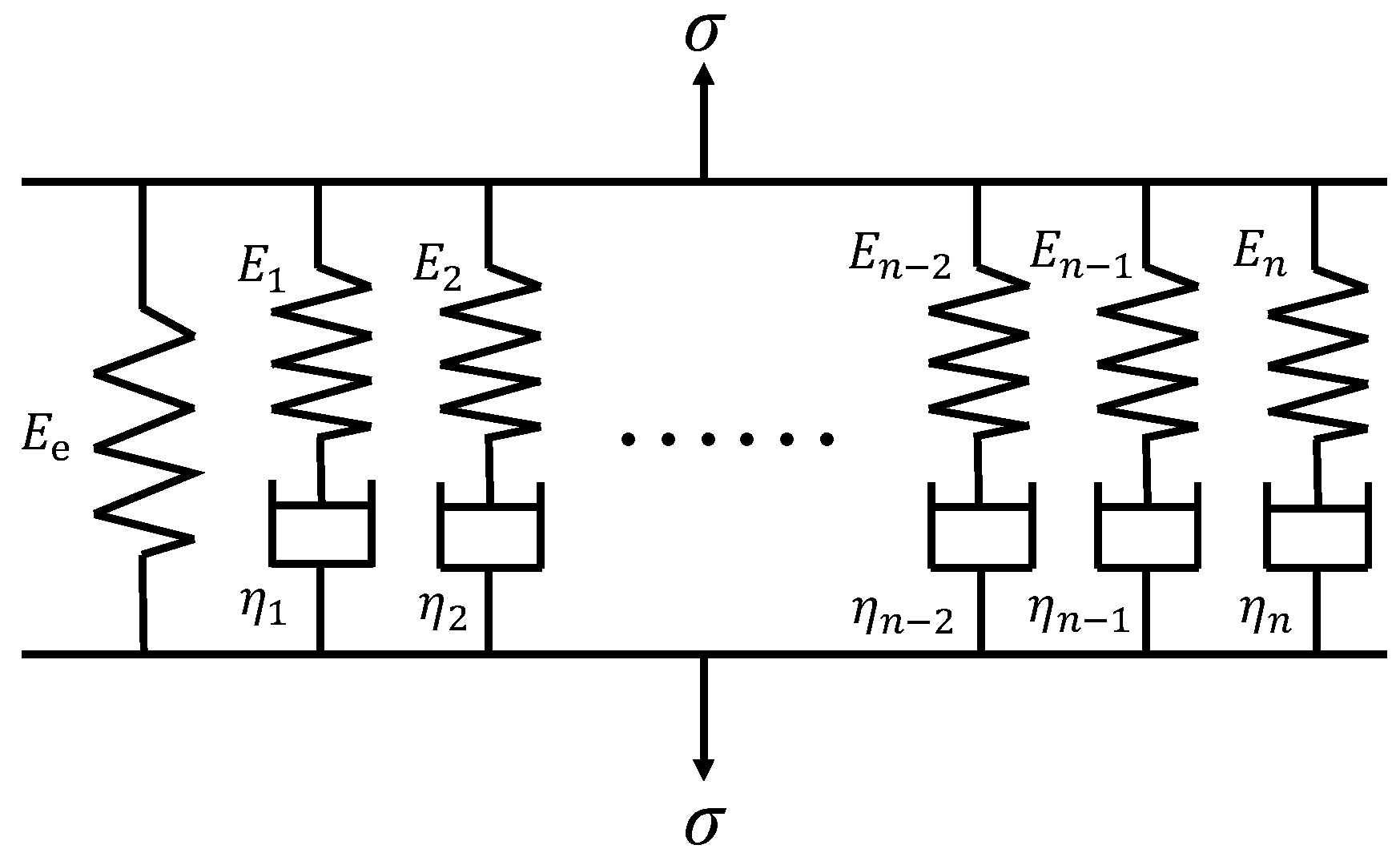
4.2. Determination of Viscoelastic Parameters Based on Generalized Maxwell Model

The generalized Maxwell model, as shown in Figure 9, is widely used to describe the linear viscoelastic behavior in the finite element software because the relaxation modulus can be expressed by Prony series in the following equation [22]:
E ( t ) = E e + i = 1 n E i e t / τ i
where E(t) is the relaxation modulus, Ee is the long-term equilibrium modulus, Ei is the spring modulus in the ith Maxwell model, ηi is the dashpot viscosity in the ith Maxwell model, and τi = ηi/Ei is the relaxation time.
Through Fourier transform, the storage modulus and loss modulus of Generalized Maxwell Model can be derived as:
E ( ω ) = E e + i = 1 n E i ω 2 τ i 2 1 + ω 2 τ i 2
E ( ω ) = i = 1 n E i ω τ i 1 + ω 2 τ i 2
in which E ( ω ) is the storage modulus, E ( ω ) is the loss modulus, and ω = 2πf is the angular frequency (rad/s).
According to the relationship between dynamic modulus, phase angle, storage modulus and loss modulus:
| E * ( ω ) | = [ E ( ω ) ] 2 + [ E ( ω ) ] 2
tan φ ( ω ) = E ( ω ) E ( ω )
then the related parameters in the generalized Maxwell model can be determined by the optimization method through the following objective function:
minmize e r r o r = 1 N { i = 1 N [ 1 | E * ( ω i ) | Modelled | E * ( ω i ) | Mastercurve ] 2 + i = 1 N [ 1 φ ( ω i ) Modelled φ ( ω i ) Mastercurve ] 2 }
where N is the total number of sample data obtained from the master curve, the subscript modelled means the data is predicted by the generalized Maxwell model, and the subscript Mastercurve means the data is obtained from the master curve.
Both the dynamic modulus and phase angle are considered in Equation (10) because the overall viscoelastic properties of the material cannot be accurately reflected by only one component, such as dynamic modulus or phase angle [23]. In order to facilitate the solution of the optimization problem, the relaxation time τi is specified in this study, varying from 10−6 to 104 s. The viscoelastic parameters from the results of dynamic modulus at the reference temperature of 20 °C in Figure 8 are listed in Table 3 and can be used as the input parameters of material property for the later finite element analysis.

5. Numerical Model

In terms of full cross-section ACWL, it also plays an important role in load transfer in addition to the waterproof function. So, it is necessary to study the dynamic behavior of railway structure with ACWL through the finite element analysis method to ensure that the structure can meet the requirements of long-term stability and deformation control of the line. In this section, the standard 3D model of CRTS III ballastless track structure, which is widely used in China, was established using ABAQUS software to investigate the influence of ACWL on the dynamic response of the track structure. The vehicle-track interaction behavior was also taken into consideration in the model.

5.1. Vehicle Model

The high-speed train in the model is considered as a multiple rigid body with a double suspension system, as is illustrated in Figure 10. The single-carriage vehicle system consists of the vehicle body, two bogies and four wheelsets. The vehicle body and the bogie each have five degrees of freedom, namely, lateral, vertical, rolling, yawing and pitching movements. The wheelsets have four degrees of freedom, including lateral, vertical, yawing and pitching movements. The suspension system of the vehicle model is realized by using the connector element in the software. In this paper, the vehicle parameters of CRH3 high-speed train are used for analysis and the relevant parameters can be found in reference [24].

5.2. Wheel–Rail Contact Model

The contact relationship between wheel and rail is the key to study the coupled effect of vehicle-track structure interacted system. The contact properties between wheel and rail include the normal behavior and the tangential behavior between the contact faces. The nonlinear Hertz contact model is used to wheel–rail normal contact force P(t) in the following equation:
P ( t ) = [ 1 G Δ Z ( t ) ] 3 / 2
where G is the wheel–rail contact constant (m/N3/2) and ΔZ(t) is the value of elastic compression at the contact surface between the wheel and rail (m).
For the LM wheel tread adopted in this research, G can be calculated as follows:
G = 3.86 R 0.115 × 10 8
where R = 0.43 m is the rolling radius of the wheel.
The coulomb friction model is used to describe the tangential behavior of wheel–rail contact and the friction force F is expressed as:
F = μ P ( t )
where μ is the friction coefficient between wheel and rail and can be calculated using the exponential decay model:
μ = μ k + ( μ s μ k ) e β v
in which μk is the dynamic friction coefficient, μs is the static friction coefficient, β is the exponential decay coefficient and v is the relative sliding speed of the contact surface. The wheel–rail contact model developed in ABAQUS is illustrated in Figure 11.

5.3. Track Structure Model

The geometric parameters track structure model was obtained from the “Code for Design of High Speed Railway” in China (TB 10621-2014) [25]. The CRTS III track structure system consists of rail, fastener, track slab, self-compacting concrete (SCC), base plate, ACWL, roadbed, subgrade and soil foundation from top to bottom. The Chinese 60 kg/m rail with a standard gauge of 1.435 m and WJ-8B fastener with a spacing of 0.63 m were adopted in the model. The standard CRTS III P5600 track slab has a length of 5.6 m, a width of 2.5 m and a thickness of 0.2 m. The SCC has the same length and width as the track slab and the thickness is 0.1 m. The length, width and thickness of base plate is 16.99 m, 3.1 m, 0.3 m, respectively. The expansion joints are taken into consideration in the model and the width of the expansion joint for the track slab and base plate is 70 mm and 20 mm, respectively. So, there are three track slabs on a base plate. The double line subgrade with a surface width of 13.6 m for the ballastless track structure is used in the model and the gradient of subgrade slope is 1:1.5. The standard thickness of surface layer and bottom layer of roadbed is 0.4 m and 2.3 m, respectively. The thickness of ACWL is included in the surface layer of roadbed. The thickness of subgrade and soil base is set as 3 m and 5 m, respectively, to reduce the influence of the bottom boundary condition on the analysis results.
The linear elastic constitutive relationship is used to simulate the track structure model except the ACWL and the material parameters are listed in Table 4. The ACWL is considered as a linear viscoelastic material in the model according to the results in Table 3. The Rayleigh damping determined by modal analysis is also considered in the model [26]. The eight-node hexahedral solid element is used to mesh the track structure model. The Cartesian connector element is used to simulate the fasteners. The elastic stiffness and damping coefficient of fasteners is 30 kN/mm and 60 kN·s/m. The structural layers in the track structure system are considered to be completely continuous. The encastre boundary condition is set at the bottom of model and the symmetry boundary condition is set at both the longitudinal and lateral ends. To eliminate the influence of boundary conditions, especially the dynamic wave, on the calculation results, the distance of five base plates along the driving direction is used in the model. The calculated results of dynamic responses are obtained from the region at the middle base plate. Finally, the entire finite element model for the CRTS III ballastless railway with ACWL is illustrated in Figure 12.

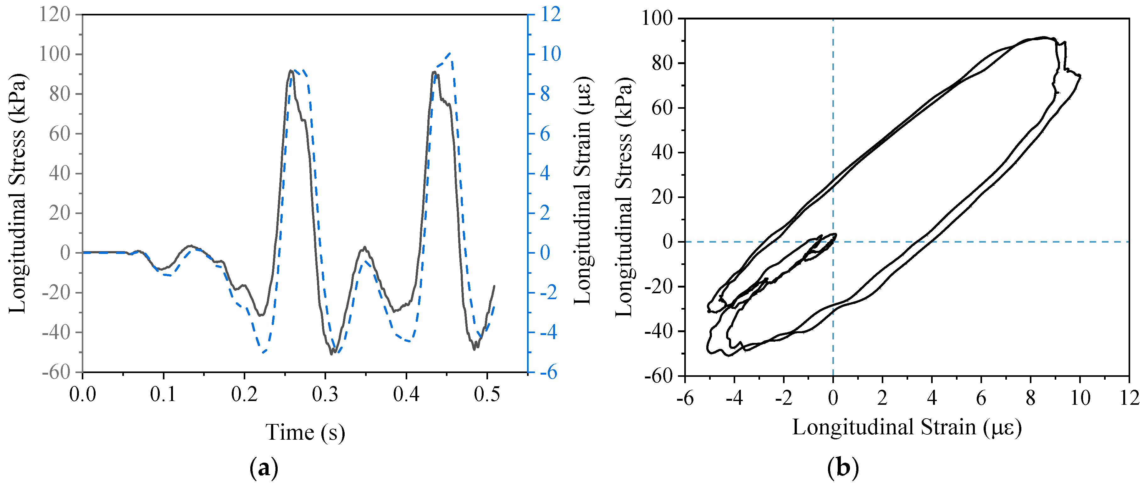
5.4. Model Verification

To verify the reliability of the model, the calculated results are compared with the field test data. A dynamic performance test system was set in the ACWL test section on the Zhengzhou–Xuzhou high-speed railway at 2016. The sensors to monitor the acceleration and dynamic displacement were embedded in the ACWL and the buried position was below the rail. The monitor sections were selected at the center line and the joint of the base plate, respectively. The measured data showed that the vertical displacement was about 0.01~0.5 mm, and the vertical acceleration is about 1.6~3.2 m/s2 [27]. The related parameters in the model is adjusted according to the structural conditions of the test section on the Zhengzhou–Xuzhou high-speed railway. The dynamic responses of ACWL below the center line of the base plate are calculated by the model when the train speed is 350 km/h, as shown in Figure 13. It can be observed from Figure 13a,b that the peaks of acceleration and displacement are basically within the range of test data, which proves the reliability of the model. It is indicated that the dynamic loading effect of the two wheelsets under a single bogie is superimposed in the ACWL because the curves in Figure 13 have two peaks instead of four peaks.

6. Result Analysis and Discussion

6.1. Analysis of Critical Loading Position

The train load at different positions along the driving direction causes different stress distributions in the ACWL, so it is necessary to determine the critical loading position when designing the structural layer of ACWL. The critical loading position is the wheelset position where the dynamic responses of ACWL are maximum. Considering the load superposition effect, the rear wheelset of the second bogie is selected as the research target. Three load cases are compared when the train speed is 350 km/h, including the joint of base plates (Load case 1), the joint of track slabs (Load case 2) and the center of base plate (Load case 3), as is illustrated in Figure 14. The vertical stress, vertical displacement, vertical acceleration and the tensile strain at the bottom of ACWL under different load cases are calculated by the model, as summarized in Table 5.
Table 5 shows that the order of magnitude of the dynamic responses in the three cases is as follows: Load case 1 > Load case 2 > Load case 3. It is indicated that it is more unfavorable for the dynamic responses of ACWL when the wheelset is located in the structural joint, especially at the expansion joint of base plates. In terms of the tensile strain at the bottom of the ACWL, the longitudinal strain is much greater than the lateral strain, as is shown in Figure 15. It should be noted that there is a significant area of tensile strain concentration below the wheelsets in Figure 15. Overall, the tensile strain level at the bottom of ACWL is relatively low, which guarantees a long service life considering the fatigue performance.
The lateral distribution of vertical stress and displacement of ACWL under Load Case 1 is shown in Figure 16 to further investigate the unfavorable position for the ACWL in the lateral direction. The position when x = 0 m in Figure 16 denotes the center of double-line railway while x = 6.8 m denotes the outer edge near the shoulder of the roadbed. It can be observed in Figure 16a that the vertical displacement shows a large value over the width range of the base plate and reaches the maximum value near the outer edge of the base plate. In terms of the vertical stress in Figure 16b, it is obvious that the maximum value of vertical stress appears just below the two rails. Therefore, it is necessary to pay more attention to the area of ACWL near the edges of base plate and directly below the rail when designing the structural layer.

6.2. Comparison of Dynamic Responses of Track Structure with and without ACWL

The dynamic responses of track structure with and without ACWL are compared based on the numerical model in this section to discuss the mechanical function of ACWL except waterproofing. The track structure with ACWL means the surface layer of roadbed consists of 80 mm ACWL and 160 mm graded gravel layer in thickness. The thickness of the surface layer of roadbed in the traditional track structure without ACWL is also 240 mm and it is all made of graded gravel. The cement concrete waterproofing layer is used at the shoulders and between two lines in the traditional track structure. The vertical displacement and acceleration at the bottom of each layer in the track structure with and without ACWL when the train speed is 350 km/h are shown in Figure 17. It can be seen from Figure 17 that the introduction of the ACWL reduces the vertical acceleration and displacement of each layer in the track structure compared to the traditional track structure. The average decrease in vertical acceleration and displacement of track structure with the introduction of ACWL is about 13% and 9%, respectively. In terms of the vertical acceleration, ACWL has a greater influence on the adjacent structural layers, base plate and roadbed. It is also seen that ACWL is helpful for improving the settlement of the subgrade, which is a major advantage for the track structure.
The vertical displacement and stress at the bottom of roadbed in the track structure with and without ACWL are further compared in Figure 18. The peak values of the vertical displacement and stress in Figure 18 decreased by 14.5% and 20.3%, respectively, when the ACWL is included in the roadbed. The reason for the decrease in the dynamic responses at the bottom of roadbed is due to the viscoelastic characteristics of asphalt concrete. The viscous component in the asphalt concrete is capable of hysteresis recovery and energy dissipation. The asphalt concrete can convert part of the kinetic energy transmitted by the superstructure into heat energy and dissipate it in the surrounding environment, which can reduce the vibration of the track structure. To better describe the damping mechanism of ACWL, the time history of the longitudinal stress and strain at the bottom of ACWL is shown in Figure 19a. It is obvious from the Figure 19a that the strain curve lags behind the stress curve due to the viscous components of asphalt concrete. The stress–strain curve is also shown in Figure 19b. The stress–strain curves of elastic materials during the loading and unloading process are straight lines. However, the stress–strain curve at the bottom of ACWL in Figure 19b is a loop, which indicates that energy loss occurs during the loading and unloading process because of the energy dissipation effect of viscous components. Therefore, ACWL is beneficial for improving the stress of the whole track structure and can also reduce the settlement deformation of the subgrade.

7. Conclusions

According to the laboratory test results, construction of test section and numerical simulation for the ACWL in the ballastless track, the main conclusions of this research are summarized as follows:
  • The main technical requirements of asphalt mixture for the ACWL were proposed based on the laboratory tests, including rutting test, fatigue test, low temperature bending test, immersion Marshall test and freeze–thaw split test. A test section of ACWL for the ballastless railway was constructed in north China and the field test results prove that the proposed requirements are reasonable and reliable.
  • The viscoelastic properties of asphalt concrete obtained from the ACWL in the test section were investigated based on the dynamic modulus test. The Prony series for the generalized Maxwell is an effective tool to convert dynamic modulus to relaxation modulus in the linear viscoelastic domain, which contributes to the implementation of viscoelastic constitutive relationship in the finite element model.
  • The reliability of the developed 3D finite element model was proved by the field measured data. The results indicate that it is unfavorable for the dynamic responses of ACWL when the wheelset is located at the expansion joint of base plates. The tensile strain at the bottom of ACWL is generally at a relatively low level, which means the long service life of ACWL is guaranteed. Additionally, the vertical displacement and vertical stress of each structural layer are obviously reduced due to the application of ACWL in the ballastless track structure.
  • The validated 3D finite element model could be the basis for the future studies, such as the parameter sensitivity analysis and the long-term performance of the ACWL in the test section will be continuously monitored.

Author Contributions

Formal analysis, J.Z.; Funding acquisition, X.C.; Investigation, Q.F. and G.X.; Methodology, J.Z.; Resources, D.C.; Supervision, X.C.; Writing—original draft, J.Z.; Writing—review and editing, X.C.

Funding

This research was funded by National Natural Science Foundation of China (grant number 51778136).

Conflicts of Interest

The authors declare no conflict of interest.

References

  1. Fang, R.; Lu, Z.; Yao, H.; Luo, X.; Yang, M. Study on dynamic responses of unsaturated railway subgrade subjected to moving train load. Soil Dyn. Earthq. Eng. 2018, 115, 319–323. [Google Scholar] [CrossRef]
  2. Lin, Z.; Niu, F.; Li, X.; Li, A.; Liu, M.; Luo, J.; Shao, Z. Characteristics and controlling factors of frost heave in high-speed railway subgrade, Northwest China. Cold Reg. Sci. Technol. 2018, 153, 33–44. [Google Scholar] [CrossRef]
  3. Chen, X.; Tao, T.; Yang, G.; Yan, H.; Yang, J. Long-Lasting Waterproofing Solution for the Subgrade of High-Speed Railway in Cold Region. J. Test. Eval. 2019, 47, 20180046. [Google Scholar] [CrossRef]
  4. Momoya, Y.; Sekine, E. Performance-Based Design Method for Railway Asphalt Roadbed. Doboku Gakkai Ronbunshuu E 2007, 63, 608–619. [Google Scholar] [CrossRef]
  5. Teixeira, P.F.; Ferreira, P.A.; Pita, A.L.; Casas, C.; Bachiller, A. The Use of Bituminous Subballast on Future High-Speed Lines in Spain. Int. J. Railw. 2009, 2, 1–7. [Google Scholar]
  6. Rose, J.G.; Teixeira, P.F.; Veit, P. International design practices, applications, and performances of asphalt/bituminous railway trackbeds. In Proceedings of the GEORAIL 2011-International Symposium, Paris, France, 19–20 May 2011. [Google Scholar]
  7. Rose, J.G. Selected In-Track Applications and Performances of Hot-Mix Asphalt Trackbeds. In Proceedings of the 2013 Joint Rail Conference, Knoxville, TN, USA, 15–18 April 2013. V001T01A017. [Google Scholar] [CrossRef]
  8. Teixeira, P.F.; López Pita, A.; Ferreira, P.A. New possibilities to reduce track costs on high-speed lines using a bituminous sub-ballast layer. Int. J. Pavement Eng. 2010, 11, 301–307. [Google Scholar] [CrossRef]
  9. Lee, S.-H.; Choi, Y.-T.; Lee, H.-M.; Park, D.-W. Performance evaluation of directly fastened asphalt track using a full-scale test. Constr. Build. Mater. 2016, 113, 404–414. [Google Scholar] [CrossRef]
  10. Fang, M. Structural Behavior and Mix Design for Asphalt Concrete Substructures in High-speed Rail. Ph.D. Thesis, Southwest Jiaotong University, Chengdu, China, 2012. (In Chinese). [Google Scholar]
  11. Wang, Z.; Yang, J.; Chen, X. Mastic Asphalt Concrete Waterproof Layer on High-Speed Railway Subgrade in Cold Regions. In Proceedings of the Transportation Research Board 94th Annual Meeting, Washington, DC, USA, 11–15 January 2015; Transportation Research Board: Washington, DC, USA, 2015. (In Chinese). [Google Scholar]
  12. Liu, S.; Yang, J.; Chen, X.; Wang, M.; Zhou, W. Design of Asphalt Waterproofing Layer for High-Speed Railway Subgrade: A Case Study in Heilongjiang Province, China. In Proceedings of the Transportation Research Board 96th Annual Meeting, Washington, DC, USA, 8–12 January 2017; Transportation Research Board: Washington, DC, USA, 2017. [Google Scholar]
  13. Liu, S.; Yang, J.; Chen, X.; Yang, G.; Cai, D. Application of Mastic Asphalt Waterproofing Layer in High-Speed Railway Track in Cold Regions. Appl. Sci. 2018, 8, 667. [Google Scholar] [CrossRef]
  14. Di Mino, G.; Di Liberto, M.; Maggiore, C.; Noto, S. A Dynamic Model of Ballasted Rail Track with Bituminous Sub-Ballast Layer. Procedia Soc. Behav. Sci. 2012, 53, 366–378. [Google Scholar] [CrossRef] [Green Version]
  15. Ferreira, T.M.; Teixeira, P.F. Rail Track Performance with Different Subballast Solutions: Traffic and Environmental Effects on Subgrade Service Life. J. Transp. Eng. 2012, 138, 1541–1550. [Google Scholar] [CrossRef]
  16. Ramirez Cardona, D.; Di Benedetto, H.; Sauzeat, C.; Calon, N.; Saussine, G. Use of a bituminous mixture layer in high-speed line trackbeds. Constr. Build. Mater. 2016, 125, 398–407. [Google Scholar] [CrossRef]
  17. Research Institute of Highway Ministry of Transport. Standard Test Methods of Bitumen and Bituminous Mixtures for Highway Engineering; JTG E20-2011; China Communications Press: Beijing, China, 2011. (In Chinese) [Google Scholar]
  18. Research Institute of Highway Ministry of Transport. Technical Specifications for Construction of Highway Asphalt Pavements; JTG F40-2004; China Communications Press: Beijing, China, 2004. (In Chinese) [Google Scholar]
  19. Zhou, W. Study on Railway Asphalt Concrete Substructure under CRTS III Type Ballastless Track. Master’s Thesis, Southeast University, Nanjing, China, 2017. (In Chinese). [Google Scholar]
  20. Williams, M.L.; Landel, R.F.; Ferry, J.D. The Temperature Dependence of Relaxation Mechanisms in Amorphous Polymers and Other Glass-forming Liquids. J. Am. Chem. Soc. 1955, 77, 3701–3707. [Google Scholar] [CrossRef]
  21. Luo, R.; Lytton, R.L. Characterization of the Tensile Viscoelastic Properties of an Undamaged Asphalt Mixture. J. Transp. Eng. 2010, 136, 173–180. [Google Scholar] [CrossRef]
  22. Park, S.W.; Schapery, R.A. Methods of interconversion between linear viscoelastic material functions. Part I—A numerical method based on Prony series. Int. J. Solids Struct. 1999, 36, 1653–1675. [Google Scholar] [CrossRef]
  23. Zhang, Y.; Birgisson, B.; Lytton, R.L. Weak Form Equation–Based Finite-Element Modeling of Viscoelastic Asphalt Mixtures. J. Mater. Civ. Eng. 2016, 28, 04015115. [Google Scholar] [CrossRef]
  24. Lei, X.; Wu, S.; Zhang, B. Dynamic Analysis of the High Speed Train and Slab Track Nonlinear Coupling System with the Cross Iteration Algorithm. J. Nonlinear Dyn. 2016, 2016, 1–17. [Google Scholar] [CrossRef] [Green Version]
  25. National Railway Administration of the People’s Republic of China. Code for Design of High Speed Railway; TB 10621-2014; China Railway Press: Beijing, China, 2014. (In Chinese)
  26. Chen, J.; Zhou, Y. Dynamic responses of subgrade under double-line high-speed railway. Soil Dyn. Earthq. Eng. 2018, 110, 1–12. [Google Scholar] [CrossRef]
  27. Wang, M. Study on Dynamic Characteristics of Asphalt Concrete Substructures under CRTS III Type Ballastless Track. Master’s Thesis, Southeast University, Nanjing, China, 2017. (In Chinese). [Google Scholar]
Figure 1. Gradation curve of asphalt mixture.
Applsci 09 00375 g001
Figure 2. Laboratory performance tests (a) The specimen after rutting test; (b) Fatigue Test; (c) Low temperature bending test; (d) Marshall Test; (e) Indirect tensile test.
Applsci 09 00375 g002aApplsci 09 00375 g002b
Figure 3. The cross section of ballastless track structure with asphalt concrete waterproofing layer (ACWL).
Applsci 09 00375 g003
Figure 4. Construction of ACWL in the test section (a) The spread of emulsified asphalt; (b) The mixing and transportation of asphalt mixtures; (c) Paving; (d) Rolling.
Applsci 09 00375 g004
Figure 5. The compaction by the plate tamper near the structural edge.
Applsci 09 00375 g005
Figure 6. Field tests after the construction of ACWL (a) Permeability test; (b) Compactness test; (c) The sample cored from the test section.
Applsci 09 00375 g006
Figure 7. Field test results (a) Compactness; (b) Water permeability coefficient.
Applsci 09 00375 g007
Figure 8. Master curve (a) Dynamic modulus; (b) Phase angle.
Applsci 09 00375 g008
Figure 9. Generalized Maxwell Model.
Applsci 09 00375 g009
Figure 10. Vehicle system model.
Applsci 09 00375 g010
Figure 11. Wheel–rail contact model.
Applsci 09 00375 g011
Figure 12. Finite element model of China Railway Track System (CRTS) III ballasteless track structure with ACWL (a) Overall view; (b) Side view.
Applsci 09 00375 g012
Figure 13. Time history curve for the dynamic responses of ACWL (a) Vertical acceleration; (b) Vertical displacement.
Applsci 09 00375 g013
Figure 14. Three load cases to determine the critical loading position.
Applsci 09 00375 g014
Figure 15. The strain contour at the bottom of ACWL (Load case 1) (a) Lateral strain; (b) Longitudinal strain.
Applsci 09 00375 g015
Figure 16. Lateral distribution of dynamic responses of ACWL (a) Vertical displacement; (b) Vertical stress.
Applsci 09 00375 g016
Figure 17. The dynamic responses of components in the track structure with and without ACWL (a) Vertical acceleration; (b) Vertical displacement.
Applsci 09 00375 g017
Figure 18. The time history curves of dynamic responses at the bottom of roadbed in the track structure with and without ACWL (a) Vertical displacement; (b) Vertical stress.
Applsci 09 00375 g018
Figure 19. The damping mechanism of ACWL (a) Time history curve; (b) Stress–strain curve.
Applsci 09 00375 g019
Table 1. Basic properties of modified asphalt.
PropertiesTest ResultsTechnical RequirementsTest Method
Penetration (25 °C, 100 g, 5 s) (0.1 mm)71.460–80T0604
Penetration index1.6≥0.5T0604
Ductility at 5 °C (cm)41≥30T0605
Softening Point (°C)90.2≥80T0606
Dynamic viscosity at 175 °C, Pa·s1.245≤1.5T0625
Table 2. Results and technical requirements of laboratory tests.
TestTest Result (Unit)Measured ValueTechnical Requirement
Rutting testDynamic stability (cycle/mm)3231≥2400
Fatigue TestFatigue life (×104 Cycle)122.5≥20
Low temperature bending testFailure strain (με)3356≥3000
Water Stability TestResidual stability (%)92.9≥85
TSR (%)91.9≥80
Table 3. Viscoelastic parameters of the ACWL sample cored from the test section.
i1234567891011
τi(s)10−610−510−410−310−210−11101102103104
Ei(MPa)3547.03599.54204.24526.44414.13405.51825.8685.8264.977.184.0
Ee(MPa)75.3
Table 4. Material parameters of the model.
Track ComponentsModulus (MPa)Poisson RatioDensity (kg/m3)
Rail2100000.37800
Track slab360000.22500
SCC325000.22500
Base plate325000.22500
ACWLTable 3 (20 °C)0.32500
Surface layer of roadbed2000.32000
Bottom layer of roadbed1400.251800
Subgrade1100.251700
Subsoil800.251600
Table 5. Dynamic responses of ACWL under three load cases.
Dynamic Response IndexesLoad Case 1Load Case 2Load Case 3
Vertical stress (kPa)20.1819.9414.28
Vertical displacement (mm)0.370.330.26
Vertical acceleration (m/s2)3.873.503.03
Tensile strain (με)Lateral9.536.815.00
Longitudinal16.1814.3910.63

