Article

Simulation Study of Two Torque Optimization Methods for Direct Torque-Controlled Induction Motors

1
Electrical Engineering Department, Faculty of Engineering, University of Tabuk, Tabuk 47913, Saudi Arabia
2
Department of Electrical Power, Faculty of Engineering, Cairo University, Cairo 12613, Egypt
3
Department of Electrical and Electronic Engineering, Faculty of Engineering, University Malaysia Sarawak, Kota Samarahan 94300, Malaysia
*
Author to whom correspondence should be addressed.
Appl. Sci. 2019, 9(24), 5547; https://doi.org/10.3390/app9245547
Submission received: 19 August 2019 / Revised: 10 December 2019 / Accepted: 12 December 2019 / Published: 16 December 2019

Abstract

:
The simplicity and excellent dynamic performance of Direct Torque Control (DTC) make Induction Motor (IM) drives attractive for many applications that require precise torque control. The traditional version of DTC uses hysteresis controllers. Unfortunately, the nature of these controllers prevents the optimization of the inverter voltage vectors inside the flux hysteresis band. The inverter voltage vector optimization can produce fast torque response of the IM drive. This research proposes two torque optimization methods for IM systems utilizing DTC. Analysis and Matlab simulations for the proposed optimization methods prove that the torque and, consequently, the speed responses, are greatly improved. The performances of the drive system controlled by the proposed optimization methods and the traditional DTC are compared. Conversely, the effects of the parameters on the proposed optimization methods are introduced. The proposed methods greatly improve the torque and speed dynamic performances against the traditional DTC technique. However, one of the proposed optimization methods is more sensitive to IM parameter variations than the other.

1. Introduction

There are many applications that require high-performance Induction Motor (IM) drives such as electric vehicles, mine winders, high-speed elevators, machine tools, and other more sophisticated machines. These applications usually need speed–accuracy ≤0.5%, no less than 20:1 of wide-range speed control, and a speed transient response ≥50 rad/s [1,2,3,4]. Fast, transient response and accurate torque control are key to achieving a high-performance drive.
Three decades ago, direct torque control (DTC) was deemed the simplest, most accurate, and fastest torque control method for IM drives [5]. Additionally, the DTC algorithm does not depend on motor parameter variations [6,7]. Nevertheless, conventional DTC has the main disadvantage of having a wide band of inverter switching frequency, despite constant torque and flux [8]. The nature of hysteresis controllers has caused this wide inverter switching frequency to occur when being used for flux and torque. The introduction of techniques using constant sampling helped to lead to the advancement of the DTC concept. Therefore, these techniques have replaced conventional analog hysteresis controllers. Accordingly, the inverter upper switching frequency is restricted. Different additions and changes to the concept and theory of DTC regarding constant sampling frequency have been proposed by many authors [9,10,11,12,13]. The fast torque response was not considered by these researchers Kumar and Zaid [14,15].
There have been recent efforts to support the torque response of DTC in IM drives. Lascu [16] introduces a direct-torque-controlled (DTC) induction motor (IM) drive that employs feedback linearization and sliding-mode control (SMC). It is a useful and simple methodology, but has many disadvantages such as torque vibrations, huge chattering, and sonic noise Ammar [17] obtains an enhancement of SVM–DTC algorithm performance. This occurs when the super twisting, sliding mode speed controller is used rather than the PI speed controller. The optimal design selection of voltage vectors based on a fuzzy controller is introduced by Sudheer [18]. Nevertheless, the algorithm shows a 43% decrease in torque ripple compared to discrete SVM–DTC [19]. An optimized dynamic over-modulation approach is suggested by Jidin [20] to achieve a fast torque response, which decreases the response time. The downside of this approach is a poor flux response and increased harmonic content due to the use of the over-modulation procedure. The model predictive control approach has been applied to IM drives with the help of DTC principles [21,22,23]. The basic concept of a model predictive control is to calculate the suitable inverter voltage vector by utilizing a predefined cost function. Though this approach successfully reduces the ripples in flux and torque, as well as the switching losses of the inverter, it requires a high computation time [24]. Moreover, it shows a negligible improvement in the system dynamics and an increase in the motor parameter’s dependency. Artificial intelligence approaches have been applied to the DTC of IM drive systems [25,26,27] and adjusted hysteresis band techniques have been implemented for the DTC of IM drives [28].
It is well known that the optimal selection of the voltage vector has proven to provide a fast torque response for the IM drive [29]. Here, two optimization methods that modify the variable frequency DTC are introduced and compared. The proposed methods greatly improve the torque and speed dynamic performance against the traditional DTC technique. The methods involve constant sampling of the DTC and optimization for a fast torque response. Finally, the two proposed methods are derived, simulated using Matlab, and compared to the conventional DTC method. A new control algorithm is established to deliver a fast torque response and the effects of the motor parameter variations on the optimization processes are studied. The results prove that the torque optimization Method (2) does not depend on any parameters of the IM. The drive system gives typical performances and simulation results as Method (1) as those obtained with Method (2). It is concluded from the simulations that the speed responses of the proposed methods are better than the traditional due to lower settling time (12% improvement in some situations).
The paper is prepared as follows: Section 2 describes the IM torque response optimization. The torque optimization Method (1) and Method (2) are presented in Section 2.1 and Section 2.2, respectively. Section 2.3 discusses IM parameter uncertainty effects on the torque optimization Method (1). The system controllers are explained in Section 2.4. Section 3 provides a detailed discussion of the simulation results and Section 4 shows the net conclusions of the paper.

2. IM Torque Response Optimization

Both motor torque and stator flux are controlled by a hysteresis controller in traditional DTC to guarantee and secure proper operation under the hysteresis band, as seen in Figure 1. Although it is a simple controller, it has many disadvantages such as variable frequency switching and low efficiency. Another disadvantage is the lack of voltage vector optimization within the hysteresis band. The origin of this problem comes from the hysteresis controller’s nature. The hysteresis controller always chooses the previous selection within the hysteresis band [30], as indicated in Figure 1. This performance causes a weak point for the hysteresis controller when operating in discrete systems. To improve hysteresis controller performance, an optimization technique must be employed to elevate the drawback. To get a fast torque response of the IM, the optimization technique must focus on selecting the voltage vector that provides a maximum torque rate. The first step in the optimization procedure is the generation of the torque rate equation as a function of the stator voltage vectors. The second step is the optimization of the stator voltage vectors to produce the maximum rate of torque. However, the optimization process can be performed using the two methods discussed in the following sections.

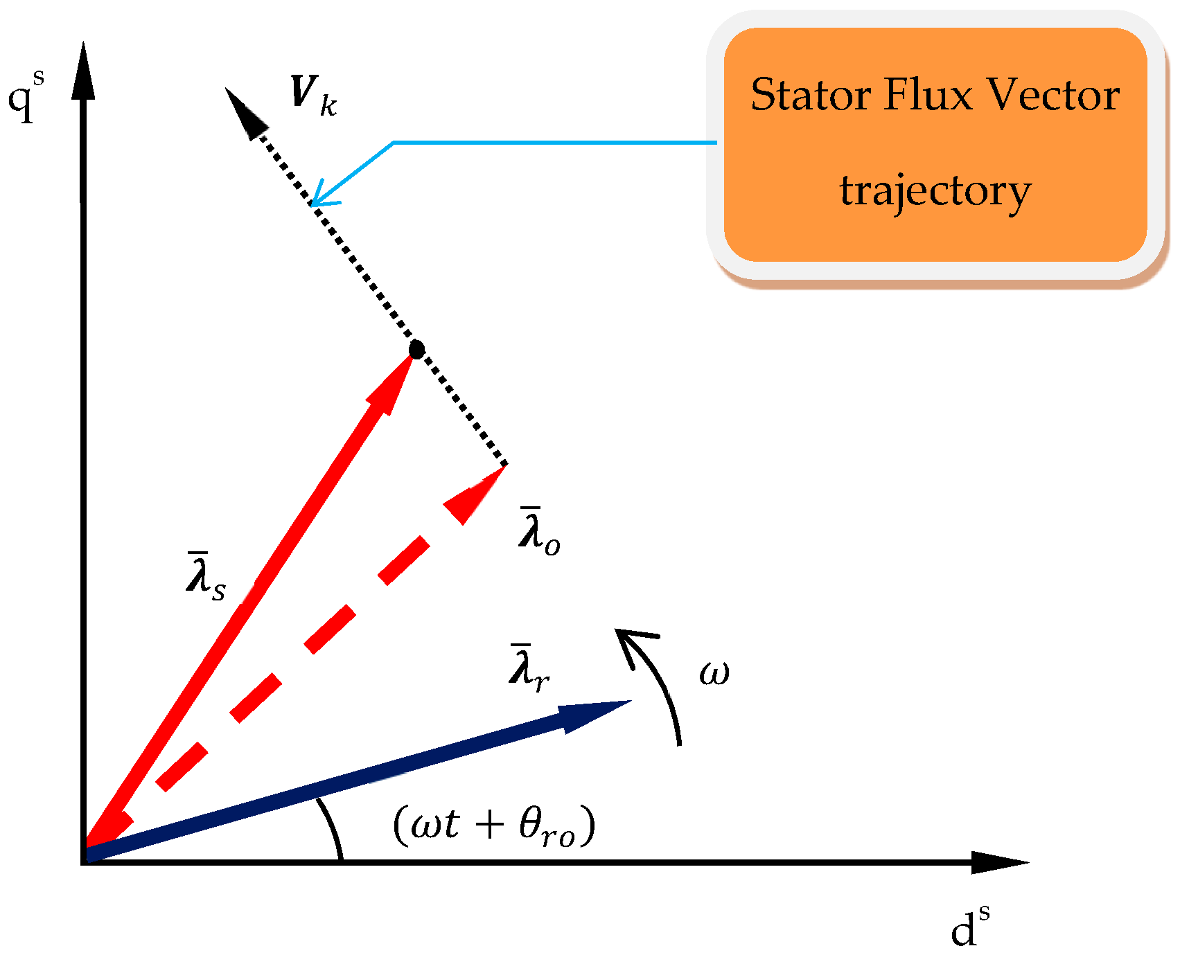
2.1. Torque Optimization Method (1)

Considering Figure 2, the IM flux vectors, stator (λs) and rotor (λr), are indicated. The applied stator voltage vector (Vk) is defined as follows:
V k = V < θ k
where ( θ k) is the angle of the voltage vector, ( k ) is the order of the voltage vector, and ( V ) is the inverter DC link voltage. Typically, the rotor time constant of IM is relatively large compared to the stator time constant [31]. Hence, the rotor flux vector is supposed to revolve with constant amplitude and speed through the changes of the stator variables [8]. The equation of the flux vector of the rotor may be represented by:
λ ¯ r = λ r ( ω t + θ r o )
where ( ω ) is the rotor flux angular speed. Suppose that the stator flux vector initial value ( λ ¯ o ) is given by:
λ ¯ s | t = 0 = λ ¯ o = λ o θ o
Assuming that the stator resistance is neglected, the stator voltage is related to the stator flux by:
V k = d λ ¯ s d t
Solving Equation (4) for the stator flux, we get:
λ ¯ s = V k t + λ ¯ o
According to Equation (5), the stator flux vector tip moves in a direction parallel to the selected voltage vector. Hence, the trajectory of the stator flux can be directed by the selected voltage vector, as shown in Figure 1. The torque equation of the IM is specified by the following:
T = k c · I m { λ ¯ s λ ¯ r * }
where (kc) is the torque constant. The time rate differentiation of Equation (6) is:
d T d t = k c · I m { d λ ¯ s d t λ ¯ r * + λ ¯ s d λ ¯ r * d t }
Incorporating Equations (2) and (5) provides the following:
{ d λ ¯ r * d t = j ω λ ¯ r * d λ ¯ s d t = V k
Therefore, substituting Equation (8) into Equation (7), the equation is as follows:
d T d t = k c · I m { V k λ ¯ r * j ω λ ¯ s λ ¯ r * }
when substituting Equation (5) into Equation (9), the equation is as follows:
d T d t = k c · I m { ( V k j ω ( V k t + λ ¯ o ) ) λ ¯ r * }
Solving for the imaginary part and substitute with t = 0 (the time of checking for the optimum voltage vector) to obtain the following:
d T d t = k c λ r [ V s i n ( θ k θ r o ) ω λ o c o s ( θ k θ r o ) ]
Using math operations and assuming that V , λ o , and ω are considered constants during the optimization process, Equation (11) can be reduced to:
d T d t = k * s i n ( θ k θ r o θ x )
where k* and ϴx are constants. Finally, the voltage vectors selection will be governed by Equation (12), which will optimize the selection to the vector that gives quick torque response. The optimization function ( f ) may be written as:
f = max k [ s i n ( θ k θ r o θ x ) ]
The main disadvantage of this method is the requirement to determine the rotor flux angle ( θ r o ). A rotor flux observer must be adapted to determine θ r o . Unfortunately, this requirement utilizes some parameters of the IM that may change with the operating conditions. A discussion of the parameter variations’ effects on this method of optimization is found in the following section.

2.2. Torque Optimization Method (2)

Since optimization Method (1) depends somewhat on motor parameters, it is better to improve it by omitting the dependence on motor parameters. The torque rate relationship in Equation (12) will be re-derived and adapted to be parameter independent. The derivation is as follows:
The IM torque equation may be written as:
T = C 1 I m { λ ¯ s * I ¯ s }
where ( C 1 ) is a constant and ( I ¯ s ) is the stator current vector. Hence, the time rate differentiation of Equation (14) is:
d T d t = C 1 · I m { d I ¯ s d t λ ¯ s * + I ¯ s d λ ¯ s * d t }
But, if:
λ ¯ s = 0 t ( V k R s I ¯ s ) d t + λ ¯ o
then:
d T d t = C 1 · I m { d I ¯ s d t ( 0 t ( V k R s I ¯ s ) d t + λ ¯ o ) * + I ¯ s ( V k R s I ¯ s ) * }
Substitute with t = 0 (the time of checking for the optimum voltage vector) to obtain the following:
d T d t = C 1 · I m { d I ¯ s d t | t = 0 λ ¯ o * + V k *   I ¯ s | t = 0 }
The right part of Equation (18) has two added terms. The first term is constant for all voltage vectors and can be neglected. To optimize, Equation (18) can be reduced to:
d T d t = C 1 · I m { V k *   I ¯ s | t = 0 }
Solving for the imaginary part and substituting with t   = 0 (the time of checking for the optimum voltage vector) will obtain the following:
d T d t = C 2 s i n ( θ i s θ k )
where θ i s is the stator current vector angle and C 2   is a constant.
The optimization function ( f ) may be written as:
f = max k [ s i n ( θ i s θ k ) ]
Through measuring the stator currents, the angle of the stator current vector can be determined. Hence, the optimization in Equation (21) does not require any parameter of the IM. Therefore, the optimization is careful, simple, and robust.

2.3. IM Parameter Uncertainty Effects on the Torque Optimization Method (1)

To discuss the effects of the uncertainty of the IM parameters on torque optimization Method (1) that is based on Equation (13), assume that the factor ( L ) is given by:
L = d T d t | k + 1 d T d t | k
The factor ( L ) is a measure for the optimization between the two adjacent voltage vectors ( k , k + 1 ) of each sector. When the sign of ( L ) is positive, then the ( k + 1 )th voltage vector is optimum and vice versa. Now, the sign of ( L ) will be checked against the IM parameter uncertainty.
Substitute Equation (12) into Equation (22) to obtain the following:
L = k * [ s i n ( θ k + 1 θ r o θ x ) s i n ( θ k θ r o θ x ) ]
Taken from the space vector relations of the inverter states, we have that ( θ k + θ k + 1 = π/3) and, using trigonometric relations:
L = k * [ c o s ( θ k + θ k + 1 2 θ r o θ x ) ]
This means that the sign of ( L ) may have an error when the cosine angle becomes near the 90° angle and its odd multipliers. Hence, we have:
θ k + θ k + 1 2 θ r o θ x = 2 n + 1 2 π
where ( n ) is an integer.
Accordingly, the value of the factor ( L ) is around zero. Hence, the torque rates of the vectors are nearly the same. Consequently, the optimization process is not valuable at these points. Typically, the rotor angle estimation error is less than ±9%. The corresponding uncertainty change in ( L ) is less than 30%. However, the optimization is considered valuable when the value of ( L ) is larger than 50% [8]. The optimization process of Method (1) is less sensitive to the uncertainty of the IM parameters.

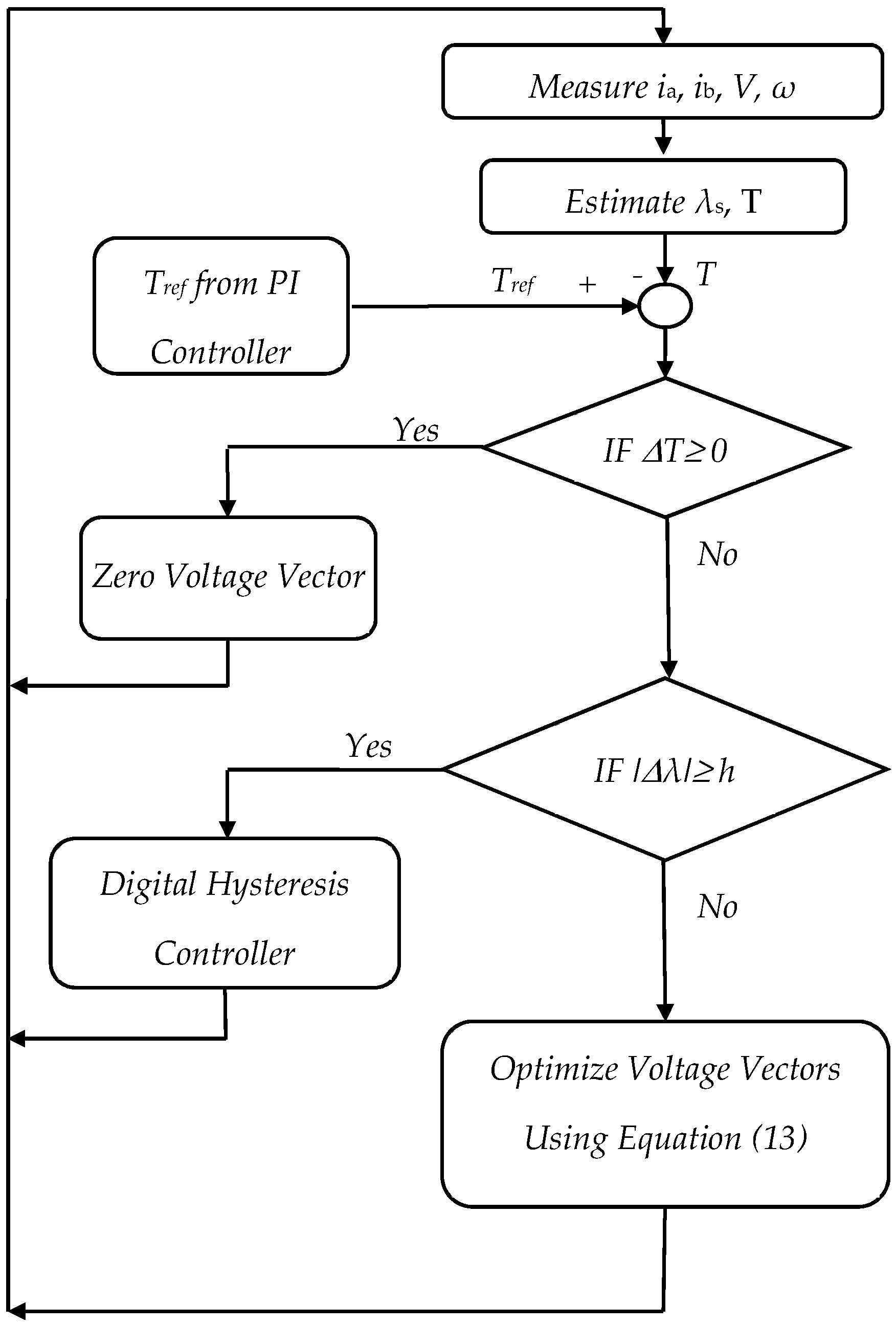
2.4. System Controller

A block diagram of the control system of Method (2) is shown in Figure 3. It is the same as that of Method (1) except there is no rotor flux observer and the optimization Equation (13) is replaced by Equation (21). The whole control system is working with digital signals and given sampling time. The controller inputs are the measured currents and DC link voltage. Simple estimators are implemented for the stator flux and torque. However, another estimator for the rotor flux angle is required for Method (1). A detailed flow chart for the control algorithm of optimization Method (2) is shown in Figure 4. The block diagram in Figure 3 represents proposed control Method (1) with the dashed arrow for the rotor angle ( θ r o ). Additionally, the control flow chart of Figure 4 is typical for Method (1) except for the estimator of ( θ r o ) and the optimization Equation (21).

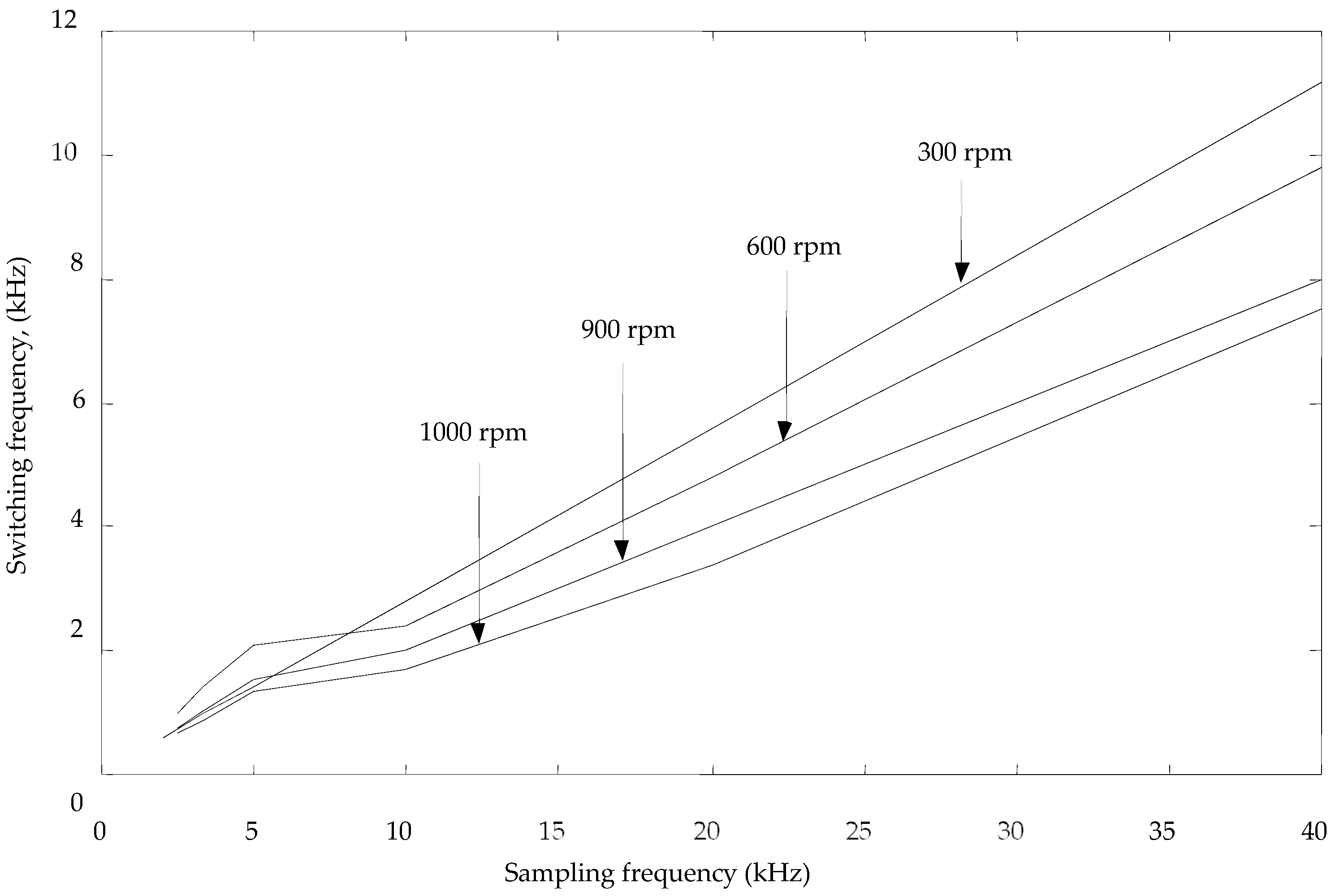
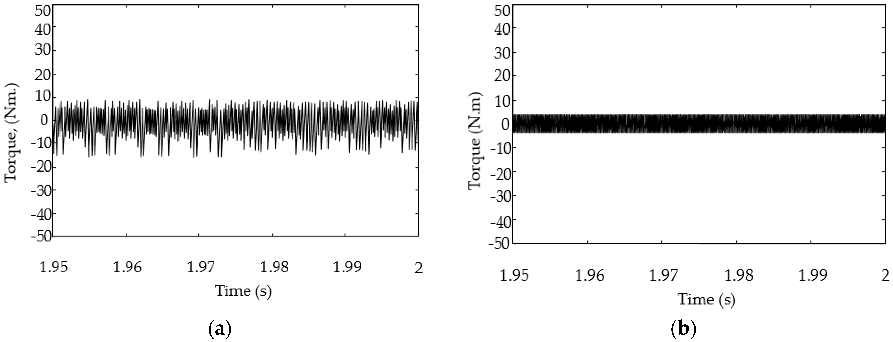
3. Simulation Results and Discussion

A Matlab/Simulink simulation package is utilized to simulate the IM speed-controlled drive with the conventional DTC and the two proposed methods. The drive system has an IM of a nameplate and circuit parameters shown in Table 1. Usually, the reference stator flux is the rated value of the IM, which is pre-calculated from the IM parameters. The speed controller is a simple Proportional Integral (PI) that is tuned using Nicola–Ziglar methodology. Figure 3 shows how the speed controller produces the reference torque for the system according to the speed error—as the reference values of the stator flux and torque are determined, the DTC algorithm starts. During this research, we compare three DTC algorithms, the conventional DTC, the proposed optimization Method (1), and the proposed optimization Method (2). The hysteresis tolerances of the flux and torque are 5% and 8%, respectively.
A simulation for proposed system with optimization Method (2) was conducted to compare with the results of optimization Method (1). The simulation results indicate the same improvement in the transient performance as that of Method (1), but with perfect identification of the motor parameters. The simulation was conducted assuming that the motor parameters were constants during operation. When there was incorrect identification or parameter changes, Method (1) performance deteriorated while the performance of Method (2), which did not have parameters, remained unchanged. The torque step response of Method (2) and Method (1) compared to the conventional DTC is shown in Figure 5. It is noted that the response of Method (2) is similar to that of Method (1), except near the full load torque. This may be due to the approximations made in Equation (13). Method (2) possesses a significant advantage over Method (1) since Method (2) does not have any motor parameters except for Rs. The drive system gives the same performance and simulation results with Method (1) as with Method (2). The simulation results for Method (2) are typically the same as the results obtained with Method (1). These results have been omitted to avoid repetition.
The speed step responses of the conventional DTC compared to proposed Method (1), are shown in Figure 6. The reference speed is 25% of the rated speed at full load conditions. It is concluded from Figure 6 that the speed response of Method (1) is better than the traditional response due to a lower settling time (12% improvement). Figure 7 compares the tip trace of the stator flux vector of the traditional DTC and that of proposed optimization Method (1). The stator flux trace of Method (1) is better than the trace of the traditional DTC. Using the method of the least squares, the error in the stator flux value for the traditional DTC is greater than the error with Method (1) by 9%. Hence, proposed Method (1) has a better stator flux response, at steady-state, than the conventional DTC.
Figure 8 shows the effect of changing the controller sampling period on the inverter switching frequency of proposed Method (1) at different operating speeds and full load conditions. It is clear that, as the sampling frequency increases, the switching frequency increases. However, the traditional DTC has a variable frequency. Its average value at full load conditions was nearly 200% of proposed Method (1). Hence, the switching losses and system efficiency of the proposed systems are better than the traditional DTC. The relationship between the IM torque error and the sampling frequency is shown in Figure 9. The figure indicates that the torque error can be reduced by increasing the sampling frequency. Conversely, the switching frequency will increase if the sampling is increased.
Figure 10 presents the torque steady-state error for proposed Method (1) and the traditional DTC. The torque error of the traditional DTC is a constant compared to proposed Method (1), which is relatively greater than that of the traditional.
Figure 11 shows the comparison of the speed response of proposed Method (2) and the traditional DTC at different set speed values and torque loads. Changing the set value with the PI controller gives an unacceptable system response [32]. Hence, the PI controller is replaced by an adaptive PI controller in this situation. Seen at all set points, there were no overshoots and no steady-state errors. The settling time differs according to the set value. The step changes of the load torque barely affect the IM speed due to the high performance of the adaptive controller. Figure 11 shows the response of the system using proposed Method (2) and how the response is faster than the traditional DTC response. It is noted that the responses may be typical at some set points. The cause of this phenomenon is that the optimization of the voltage vector is always performed between two vectors inside the hysteresis band. Sometimes the result of the optimization is similar to that given by the traditional DTC. This produces the same speed response in random situations. However, the proposed methods give a response that is equal to or faster than that of the traditional DTC.

4. Conclusions

Two torque optimization techniques for DTC IM drives were proposed. The techniques greatly improved the torque and speed dynamic performances against the traditional DTC technique. Detailed discussions, comparisons, and simulations for the two proposed methods were presented. Alternately, the uncertainty study of the IM parameters on proposed optimization Method (1) was introduced. The results prove that the torque optimization Method (2) does not depend on any parameters of the IM. The drive system gave typical performances and simulation results with Method (1) as those obtained with Method (2). It is noted that the speed responses of the proposed methods and the traditional DTC may be typical at some set points. The cause of this phenomenon is that the optimization of the voltage vector is always performed between two vectors inside the hysteresis band. Sometimes the result of the optimization is typical to that given by the traditional DTC. This produces the same speed response in random situations. However, the proposed methods either gave a faster response or were equal to the traditional DTC.

Author Contributions

S.A.Z. conceived and designed the system model. S.A.Z. and H.A. discussed the results. Y.M.B. reviewed the paper. All authors have read and agreed to the published version of the manuscript.

Funding

This research received no external funding.

Conflicts of Interest

The authors declare no conflict of interest.

References

  1. Vas, P. Sensorless Vector and Direct Torque Control; Oxford Univ. Press: New York, NY, USA, 1998. [Google Scholar]
  2. Kazmierkowski, M.P.; Franquelo, L.G.; Rodriguez, J.; Perez, M.A.; Leon, J.I. High-Performance Motor Drive. IEEE Ind. Electron. Mag. 2011, 27, 6–26. [Google Scholar] [CrossRef] [Green Version]
  3. Lascu, C.; Boldea, I.; Blaabjerg, F. A modified direct torque control for induction motor sensorless drive. IEEE Trans. Ind. Appl. 2000, 36, 122–130. [Google Scholar] [CrossRef]
  4. Buja, G.S.; Kazmierkowski, M.P. Direct torque control of PWM inverter—Fed AC motors. IEEE Trans. Ind. Electron. 2004, 51, 744–757. [Google Scholar] [CrossRef]
  5. Tiitinen, P.; Pohjalianen, P.; Lalu, J. The next generation motor control method DTC. Revue ABB 1995, 3, 19–24. [Google Scholar]
  6. Takahashi, I.; Noguchi, T. A New Quick Response and High-Efficiency Control Strategy of an Induction Motor. IEEE Trans. Ind. Appl. 1986, 22, 820–827. [Google Scholar] [CrossRef]
  7. Alsofyani, I.M.; Bak, Y.; Lee, K. Fast Torque Control and Minimized Sector-Flux Droop for Constant Frequency Torque Controller based-DTC of Induction Machines. IEEE Trans. Power Electron. 2019, 34, 12141–12153. [Google Scholar] [CrossRef]
  8. Zaid, S.A.; Mahgoub, O.A.; El-Metwally, K.A. Implementation of a New Fast Direct Torque Control Algorithm for Induction Motor Drives. IET Electr. Power Appl. 2010, 4, 305–313. [Google Scholar] [CrossRef]
  9. Patil, U.V.; Suryawanshi, H.M.; Renge, M.M. Closed-loop hybrid direct torque control for medium voltage induction motor drive for performance improvement. IET Power Electron. 2014, 7, 31–40. [Google Scholar] [CrossRef]
  10. Rosic, M.M.; Bebic, M.Z. Analysis of torque ripple reduction in induction motor DTC drive with multiple voltage vectors. Adv. Electr. Comput. Eng. 2015, 15, 105–114. [Google Scholar] [CrossRef]
  11. Carmeli, M.S.; Mauri, M. Direct Torque Control as a variable Structure control: Existence Conditions Verification and Analysis. Electr. Power Syst. Res. 2011, 81, 1188–1196. [Google Scholar] [CrossRef]
  12. Zhang, Z.; Tang, R.; Bai, B.; Xie, D. Novel Direct Torque Control Based on Space Vector Modulation with Adaptive Stator Flux Observer for Induction Motors. IEEE Trans. Magn. 2010, 46, 3133–3136. [Google Scholar] [CrossRef]
  13. Shyu, K.-K.; Lin, J.-K.; Pham, V.-T.; Yang, M.-J.; Wang, T.-W. Global Minimum Torque Ripple Design for Direct Torque Control of Induction Motor Drives. IEEE Trans. Ind. Electron. 2010, 57, 3148–3156. [Google Scholar] [CrossRef]
  14. Kumar, R.H.; Iqbal, A.; Lenin, N.C. Review of recent advancements of direct torque control in induction motor drives – a decade of progress. IET Power Electron. 2018, 11, 1–15. [Google Scholar] [CrossRef]
  15. Mohamed, E.; El-Shimy, S.A. Zaid 2 Fuzzy PID Controller for Fast Direct Torque Control of Induction Motor Drives. JES J. Electr. Syst. 2016, 12, 687–700. [Google Scholar]
  16. Lascu, C.; Jafarzadeh, S.; Fadali, M.S.; Blaabjerg, F. Direct Torque Control with Feedback Linearization for Induction Motor Drives. IEEE Trans. Power Electron. 2017, 32, 2072–2080. [Google Scholar] [CrossRef]
  17. Ammar, A.; Benakcha, A.; Bourek, A. Closed-loop torque SVM-DTC based on robust super twisting speed controller for induction motor drive with efficiency optimization. Int. J. Hydrogen Energy 2017, 42, 17940–17952. [Google Scholar] [CrossRef]
  18. Sudheer, H.; Kodad, S.F.; Sarvesh, B. Improvements in direct torque control of induction motor for a wide range of speed operation using fuzzy logic. J. Electr. Syst. Inf. Technol. 2017. accepted. [Google Scholar] [CrossRef]
  19. Casadei, D.; Serra, G.; Tani, A. Implementation of a direct torque control algorithm for induction motors based on discrete space vector modulation. IEEE Trans. Power Electron. 2000, 15, 769–777. [Google Scholar] [CrossRef]
  20. Jidin, A.; Idris, N.R.; Yatim, A.H.M.; Sutikno, T.; Elbuluk, M.E. Simple Dynamic Over modulation Strategy for Fast Torque Control in DTC of Induction Machines With Constant-Switching-Frequency Controller. IEEE Trans. Ind. Appl. 2012, 47, 2283–2291. [Google Scholar] [CrossRef]
  21. Wang, F.; Li, S.; Mei, X.; Xie, W.; Rodriguez, J.; Kennel, R.M. Model-based predictive direct control strategies for electrical drives: An experimental evaluation of PTC and PCC methods. IEEE Trans. Ind. Inform. 2015, 11, 671–681. [Google Scholar] [CrossRef]
  22. Ouhrouche, M.; Errouissi, R.; Trzynadlowski, A.M.; Tehrani, K.A. A novel predictive direct torque controller for induction motor drives. IEEE Trans. Ind. Electron. 2016, 63, 5221–5230. [Google Scholar] [CrossRef]
  23. Habibullah, M.; Lu, D.D.C.; Xiao, D.; Rahman, M.F. A simplified finite-state predictive direct torque control for induction motor drive. IEEE Trans. Ind. Electron. 2016, 63, 3964–3975. [Google Scholar] [CrossRef] [Green Version]
  24. Alsofyani, I.M.; Idris, N.R.N. Torque ripple reduction and fast torque control in DTC of induction machine using overlapping triangular-based constant frequency torque controller. In Proceedings of the 2016 IEEE International Conference on Power and Energy (PECon), Melaka, Malaysia, 28–29 November 2016; pp. 194–198. [Google Scholar] [CrossRef]
  25. Sung, G.-M.; Wang, W.-Y.; Lin, W.-S.; Yu, C.-P. Predictive Direct Torque Control Application-Specific Integrated Circuit of an Induction Motor Drive with a Fuzzy Controller. J. Low Power Electron. Appl. 2017, 7, 15. [Google Scholar] [CrossRef] [Green Version]
  26. Pimkumwong, N.; Wang, M.-S. Online Speed Estimation Using Artificial Neural Network for Speed Sensorless Direct Torque Control of Induction Motor Based on Constant V/F Control Technique. Energies 2018, 11, 2176. [Google Scholar] [CrossRef] [Green Version]
  27. Casadei, D.; Serra, G.; Tani, A.; Zarri, L. Direct Torque Control for Induction Machines: A technology status review. In Proceedings of the 2013 IEEE Workshop on Electrical Machines Design, Control, and Diagnosis (WEMDCD), Paris, France, 11–12 March 2013; pp. 117–129. [Google Scholar] [CrossRef]
  28. Jun-Koo, K.; Dae-Woong, C.; Seung-Ki, S. Direct torque control of induction machine with variable amplitude control of flux and torque hysteresis bands. In Proceedings of the IEEE International Electric Machines and Drives Conference. IEMDC’99. Proceedings (Cat. No.99EX272), Seattle, WA, USA, 9–12 May 1999; pp. 640–642. [Google Scholar] [CrossRef]
  29. Alsofyani, I.M.; Idris, N.R.N.; Lee, K. Dynamic Hysteresis Torque Band for Improving the Performance of Lookup-Table-Based DTC of Induction Machines. IEEE Trans. Power Electron. 2018, 33, 7959–7970. [Google Scholar] [CrossRef]
  30. Berzoy, A.; Rengifo, J.; Mohammed, O. Fuzzy Predictive DTC of Induction Machines with Reduced Torque Ripple and High-Performance Operation. IEEE Power Electron. 2018, 33, 2580–2587. [Google Scholar] [CrossRef]
  31. Shukla, S.; Singh, B. Reduced-Sensor-Based PV Array-Fed Direct Torque Control Induction Motor Drive for Water Pumping. IEEE Trans. Power Electron. 2019, 34, 5400–5415. [Google Scholar] [CrossRef]
  32. Kazemian, H.B. Comparative study of a learning fuzzy PID controller and a self-tuning controller. ISA Trans. 2001, 40, 245–253. [Google Scholar] [CrossRef]
Figure 1. The effect of voltage vector selection on the flux vector trajectory in the hysteresis band region.
Applsci 09 05547 g001
Figure 2. The trajectory of the rotor and stator flux vectors.
Applsci 09 05547 g002
Figure 3. The block diagram of the proposed DTC utilizing optimization Method (2).
Applsci 09 05547 g003
Figure 4. The flow chart of the Control algorithm for Method (2).
Applsci 09 05547 g004
Figure 5. The step torque response of the proposed methods with the conventional DTC; at no load.
Applsci 09 05547 g005
Figure 6. The speed responses of the conventional and proposed Method (1); at rated load.
Applsci 09 05547 g006
Figure 7. The stator flux trace of (a) Method (1) (b) traditional DTC.
Applsci 09 05547 g007
Figure 8. The relationship between the inverter switching frequency and the sampling frequency at different speeds and full load conditions.
Applsci 09 05547 g008
Figure 9. The relation between the IM torque error and the inverter sampling frequency.
Applsci 09 05547 g009
Figure 10. The torque steady-state error of (a) Method (1) and (b) the traditional DTC.
Applsci 09 05547 g010
Figure 11. The speed response comparison of proposed Method (2) and the traditional DTC, at different speed set values and load torque changes.
Applsci 09 05547 g011
Table 1. System Parameters.
IM RatingIM Equivalent Circuit Parameters
10 KW, 6 pole, 220V, 60 HzRs = 0.294 ΩLm = 0.041 HLs = 0.0424 Hλs = 0.454 Wb
Rr = 0.156 ΩLr = 0.0417 HJ = 0.4 kgm2

