Abstract
Conventional navigation systems used in transsphenoidal pituitary surgery have limitations that may lead to organ damage, including long image registration time, absence of alarms when approaching vital organs and lack of 3-D model information. To resolve the problems of conventional navigation systems, this study proposes a U-Net-based, automatic segmentation algorithm for optical nerves and internal carotid arteries, by training patient computed tomography angiography images. The authors have also developed a bendable endoscope and surgical tool to eliminate blind regions that occur when using straight, rigid, conventional endoscopes and surgical tools during transsphenoidal pituitary surgery. In this study, the effectiveness of a U-Net-based navigation system integrated with bendable surgical tools and a bendable endoscope has been demonstrated through phantom-based experiments. In order to measure the U-net performance, the Jaccard similarity, recall and precision were calculated. In addition, the fiducial and target registration errors of the navigation system and the accuracy of the alarm warning functions were measured in the phantom-based environment.
1. Introduction
Recently, surgeons have applied a transsphenoidal approach (TSA) to remove pituitary tumors, using an endoscope, as shown in Figure 1. This method of operation involves approaching the pituitary tumor through the shortest path—by incising the nasal septum and removing the rostrum bone. The actual clinical workflow for this procedure is shown in Figure 2. TSA surgery has evolved from surgery using a microscope to surgery using an endoscope. There are several reasons for this change. The main reason is to secure the surgeon′s field of view. When a microscope is used, no obstacle can intrude between the surgical space and the microscope. This meant that it was necessary to remove more of the body structure than was necessary. To secure the surgical space view, TSA surgery using an endoscope has been developed [1,2,3].
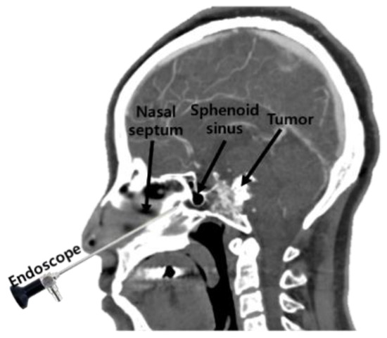
Figure 1.
The concept behind the transsphenoidal approach to pituitary surgery.
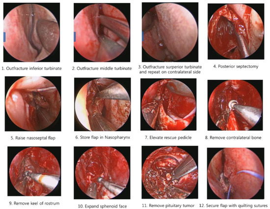
Figure 2.
Procedures in the transsphenoidal approach to pituitary surgery.
It is also difficult to identify the presence of residual tumor during tumor removal surgery. Minimally invasive surgery has become possible since the introduction of the endoscope, as it enables a minimal incision; however, there are still problems such as the difficulty in identifying residual tumors remaining after surgery and the possibility of occurrence of complications in TSA surgery. For example, a tumor in the blind region, as shown in Figure 3, is difficult to remove by relying on the endoscopic view; moreover, in minimally invasive surgery, there is always a blind region that cannot be examined using a conventional straight endoscope. Removal of tumors in this region requires a surgical navigation system, a flexible (bendable) endoscope and a bendable surgical tool [4,5,6,7,8,9,10,11].
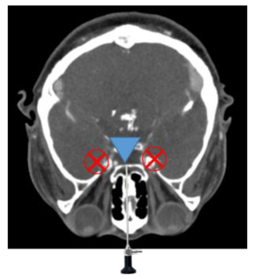
Figure 3.
Endoscope blind regions.
Previous research on bendable devices has focused on active types—with motors—using robots mounted around the surgical site, rather than the use of hand-held instruments. The issue here has been that it is difficult for a mounted type, bendable robot to respond quickly when the camera lens becomes obscured with blood, which often occurs in an actual surgical environment.
Another problem with TSA surgery is the potential for complications during tumor removal, which can include vision loss due to optic nerve damage, meningitis caused by leaking cerebrospinal fluid and stroke caused by damage to internal carotid arteries (ICAs) that are close to the sphenoidal sinus [12]. In order to avoid these complications, navigation systems have recently been introduced into the operating room [13,14]. In such a system, patient information—obtained using magnetic resonance (MR), computed tomography (CT), computed tomography angiography (CTA) and so forth, in preoperative procedures—can be used to construct three-dimensional (3-D) patient models.
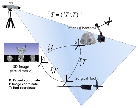
The navigation system consists of 3-D models, a registration algorithm and tracking tools. Its aim is to provide information that is difficult to identify on the endoscopic screen, such as the locations of important patient organs and the target tumor. Other advantages of a surgical navigation system are that it provides as much information as possible to the surgeon, to reduce the need for reoperations and to provide patients with the opportunity for good postoperative progress. For example, the navigation system can indicate the location of optic nerves, thus reducing the possibility of complications arising that involve loss of vision caused by invasion of the patient′s optic nerve and can also provide internal carotid artery (ICA) location information, preventing operation delays or reoperations caused by bleeding.
The last decade has seen the genesis of research into computer-assisted surgery [15,16]. Recently, future trends in computer-assisted surgery were predicted by van Oosterom et al. [17], while Chen et al. [18] investigated navigation systems for implant placement and a CT-guided, osteotomy navigation system was applied to maxilla surgery, by Hasan et al. [19].
Limitations do nonetheless exist in conventional surgical navigation systems. Firstly, the conventional surgical navigation system only provides three medical image planes of the patient and a 3-D model, without detailed information. Unless very careful segmentations are performed, it does not provide the surgeon with accurate 3-D information about vital organs, such as optic nerves or ICAs, which can be damaged during surgery. Secondly, there is no form of appropriate warning system, designed to advise the surgeon when a surgical instrument approaches a patient′s organs. Thirdly, conventional navigation systems take a long time to register the medical image, making it difficult to coordinate actions with the imagery in real time.
The use of deep learning in computer-assisted surgery has evolved quicker than expected. Deep learning is good for solving long registration times—which has been one of the problems of conventional navigation systems. Deep learning algorithms have mostly been applied to image segmentation [20,21,22], as most deep learning investigations focus on imaging, with very few cases applied to real robots or other systems. Marco et al. [23] applied deep learning for real time depth estimation from single monocular frames to the bronchoscopy field but its accuracy was limited to 1.5 mm. A navigation system with 1.5 mm accuracy would be suitable for bronchoscopy but not suitable for spinal surgery or TSA surgery that requires accuracy within 1 mm, while Laina et al. [24] proposed tracked surgical instruments using concurrent segmentation and localization architecture. Their model overcomes the specular reflections and motion blur problem using heatmap regression. Thus, it is recognized as the state-of-the-art performance in Endovis challenge. However, they have a limitation in that deep learning was applied only to image segmentation field. Esfandiari et al. [25] performed pose estimation of the pedicle screw using two networks opaque-trained network and gradient trained network simultaneously. Nevertheless, their pose estimate error was within 1.92 ± 0.55 mm.
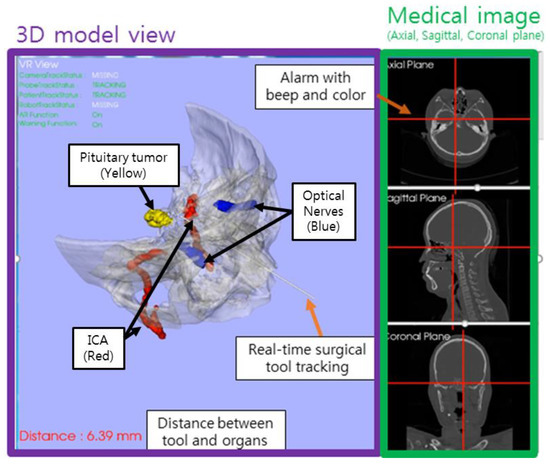
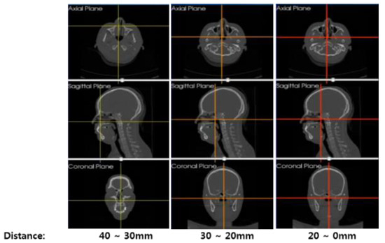
In this study, we firstly propose a U-Net-based navigation system, which provides a 3-D model of optical nerves and ICAs—which are not available in current commercial surgical navigation systems. One benefit of this proposed system is that it provides automatic segmentation of important organs, such as optical nerves and ICAs, quickly and also provides 3-D models and multi-planar imagery, giving surgeons a better understanding of individual patient anatomical structure. It also incorporates an alarm, which alerts the surgeon as the surgical tool approaches vital organs, allowing the operator to approach the surgical target cautiously. Finally, a phantom experiment was conducted to demonstrate the effectiveness of the U-Net-based surgical navigation system and the bendable endoscope and surgical tool. In addition, through the phantom experiment, the proposed U-Net based navigation system confirmed the accuracy of fiducial registration error (FRE) and target registration error (TRE) within 0.5 mm. This research was conducted with the approval of the Institutional Review Board of Yonsei University Gangnam Severance Hospital (3-2019-0343). Experiments conducted in this research can be seen in Supplementary Materials video.
2. Automatic Segmentation Using U-Net
2.1. U-Net
U-Net [26], as shown in Figure 4, is a neural network architecture proposed in deep learning; it is currently being studied in the field of medical segmentation. The U-Net structure used in this study is shown in Figure 4. The medical imaging modality used in this study is CTA and the CTA images were obtained from SOMATOM Definition AS + SIEMENS. The image obtained from the CT instrument had a size of 512 × 512 pixels and in this study, the patient CTA image dataset was provided to our U-Net model, which, according to previous research [23,24], has surpassed the performance of conventional segmentation methods when applied to medical image segmentation.
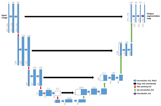
Figure 4.
U-Net neural network architecture.
U-Net architecture has two different paths—the contracting path and the symmetric expanding path. U-Net′s contracting path captures context, whereas its expanding path facilitates precise localization, enabling U-Net to overcome the trade-off relationship between context and localization observed in conventional neural networks. During up-sampling in the expanding path, image data are copied and cropped into the contracting path and are then concatenated for precise localization. This method of copying and concatenation into the contracting path was employed in our study, as shown in Figure 4. U-Net has high learning speed as there is no fully connected layer and the patch overlap rate is low. As reported in Reference [26], U-Net can also achieve good segmentation performance when trained using augmentation data. It was selected for use in this study because of its suitability for the single-graphics processing unit (GPU) environment and its ability to overcome limitations caused by the number of patient images.
In the neural network learning stage, each label data should further inform the neural network, according to the nature of supervised learning. Therefore, we needed to prepare CTA images and ground truth (label) the learning targets of this study when creating the dataset. The preparation of the dataset is explained in the next section.
2.2. Preparation of Training Data
Before image acquisition, a contrast agent is administered to patient′s blood vessels, enabling the vessels to be clearly seen in the obtained medical image, that is, the CTA. In this study, grayscale inverted CTA images were used as training data and we prepared label data via the manual segmentation of optic nerves and ICAs in a 3D slicer environment, with the labeling procedure conducted manually by surgeon Chang-Ki Hong, one of the authors of this paper. Data label was conducted using wand effect (tolerance: 10, max pixels per click: 150, fill volume mode). Our dataset included the upper part of the head, based on cervical spine 4 and did not use images below the cervical spine 4. The grayscale inverted CTA images and label data were used as a pair of inputs for training, with each single input dataset having paired CTA images and labels, as shown in Figure 5.

Figure 5.
Example of input data image and label.
Training data were collected from 1218 slices of six patients. Because there were limited patient data, 11 augmentation data elements were generated for every piece of patient data, giving a total of 13,398 data. Data augmentation applied in this study included rotation ranges of between −0.2° and 0.2°, width shift changes ranging between −25 and +25 pixels, height shift changes ranging between −25 and 25 pixels, shear angle changes (shear angle changes counter-clockwise, in degrees) ranging between 0–5° and zoom changes ranging between −5% and 5% of the image size.
2.3. U-Net Training Phase
The training phase involves a two-step learning process. The first step involves learning the patient′s image and label data and the second step involves learning the augmentation data produced from the image and label data of the first step. The reason for dividing the process into two-steps was related to the large amount of learning time needed: Learning speed was slow, making it difficult to reduce the value of the loss function. Thus, the first-step was intended to reduce the loss function, by learning 1218 slices from six patients, which aided in make learning the augmentation data in the second step faster. Another advantage was that the second-step learning result—capture of the augmentation data—improved the outcome of the first-step learning result, as U-Net learned more data during in the process of learning augmentation data. In the second learning process, not all the augmentation data were used for learning, with approximately 20% retained for use in process validation.
In the first step of the learning process, 1218 training data was trained 2000 times, which corresponded to one epoch and there were progressed 10 epochs. The dice loss function, which has become popular in medical image segmentation, was used [27]. The concept underlying its use was discussed by Fausto, et al. [28]. The dice coefficient D is expressed as shown in Equation (1):
where Y is the predicted segmentation of the neural network and X is the ground truth value. This equation indicates that if the dice coefficient was close to 1, the prediction result would be close to the ground truth value. Dice loss was defined as shown in Equation (2):
In the first step of learning, the tendency for dice loss with respect to the training epoch was calculated, giving the results shown in Figure 6.
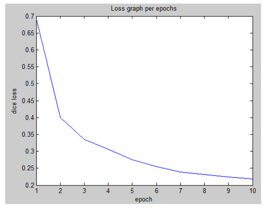
Figure 6.
First-step learning graph for dice loss per training epoch.
To achieve a more accurate prediction, the second step of the learning process was performed using the generated augmentation data. For this purpose, 10,718 samples of 13,398 data were used for re-training, with 2680 samples retained for validation and a total of 15 training epochs were performed. In the second step, the dice loss was 0.0691 and the validation loss was 0.1767. These results were extremely low in comparison with those of the first step.
The total learning time was 485 min. An NVIDIA Quadro M4000 GPU was used for the learning process, with code implemented using Tensorflow (Version 1.8.0) equipped with Keras libraries. New patient data (note: new patient data not included in the training data set) were applied to U-Net as test data and the results of U-Net for the automatic segmentation of ICAs and optic nerves are shown in Figure 7a,b respectively. The U-Net 3-D model of the segmented ICAs and optic nerves was shown in Figure 13. The times required for ICA segmentation by U-Net and by humans (manually), for 232 image slices, are presented in Table 1. U-Net-based segmentation significantly reduced the amount of time required in comparison with manual segmentation.
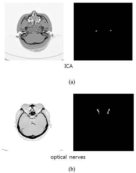
Figure 7.
Prediction results by U-Net: (a) ICAs; (b) optic nerves.

Table 1.
Time spent in ICA segmentation (232 image slices).
Jaccard similarity, precision and recall were used to quantitatively measure the accuracy of U-Net segmentation. Jaccard similarity is defined as follows:
where X represents the ground truth and Y represents the predicted U-Net result. As shown in (3), a Jaccard similarity closer to 1 indicates that X and Y are more similar. Label data produced by Chang-Ki Hong were assumed to be the ground truth values and the Jaccard similarity was calculated for each pixel between X and Y images. Precision is defined as:
Here, TP represents cases where U-Net correctly predicted ICA or optic nerve locations, while, FP represents cases where what U-Net predicted as true was actually false. Recall was defined in our study as shown in Equation (5):
FN represents cases where what U-Net predicted as false was actually true. Overall, a precision and recall close to 1 indicated that the U-Net prediction result was similar to that for the ground-truth images.
The segmentation similarity of ICAs and optic nerves using U-Net is shown in Figure 8. As shown, the Jaccard similarity for the optic nerves was relatively high in comparison with that for the ICAs, indicating that the U-Net-based learning produced relatively accurate automatic segmentation for the optic nerves. This was because the distribution of optic nerve in the CTA images was narrower than that of ICAs. Although a different trend was observed for precision and recall, indicating that while overall performance was satisfactory, based on precision and recall results, trade-offs between precision and recall existed, as can be seen in Figure 9.
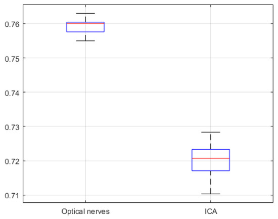
Figure 8.
U-Net network based Jaccard similarity (20 CTA image slices).
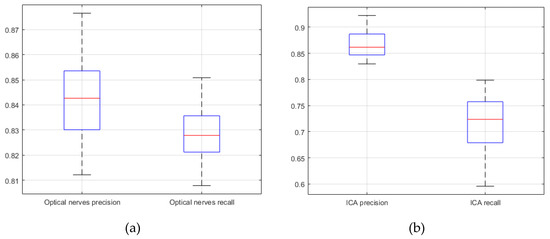
Figure 9.
U-Net network based precision and recall (20 CTA image slices). (a) optical nerves precision and recall; (b) internal carotid arteries precision and recall.
In order to compare the performance of U-Net-based learning in this study, we applied the network structures of V-Net [28] and SegNet [29]. Only the neural network structure was changed but all training conditions were identical. The V-Net has a 3D convolution layers. V-Net has a characteristic of using 3-D volume directly as input/output because of using 3D convolution layer. However, U-Net performance is better than V-Net performance because the interval of patient data in this study is not the same. SegNet is different from U-Net. SegNet has pooling indices instead of concatenation. SegNet trains faster than U-Net because there was no concatenation but the learning performance was lower than that of U-Net. The total learning time was 576 min and 281 min for V-Net and SegNet, respectively.
Comparing the results of U-Net learning with those of V-Net and SegNet revealed that U-Net exhibited the best performance as shown in Figure 8, Figure 9, Figure 10, Figure 11 and Figure 12.
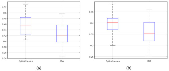
Figure 10.
Jaccard similarity; (a) V-Net (b) SegNet (20 CTA image slices).
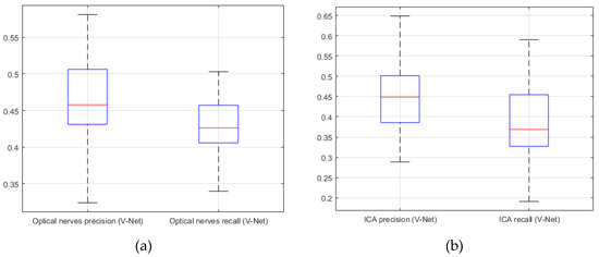
Figure 11.
V-Net. (a) precision; (b) recall (20 CTA image slices).
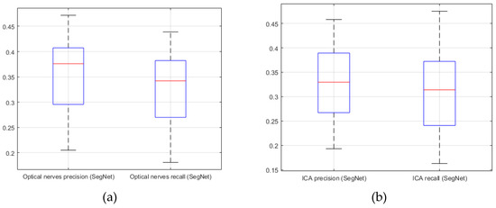
Figure 12.
SegNet. (a) precision; (b) recall (20 CTA image slices).
4. Design of the Bendable Endoscope, Surgical Tool and Phantom Design
4.1. Design of Bendable Endoscope and Surgical Tool
In contrast to previously developed devices [4,5,6,7,8,9,10,11], we developed a bendable device for pituitary surgery which did not use motors, instead employing a passive, hand-held mechanism incorporating an end-effector designed to be bent through 90° by turning a lever. The bendable device pulls two wires through a pulley to cause bending and as shown Figure 17, a worm wheel was installed in the middle of the rotary shaft of the pulley, with a worm gear installed on the same axis as the lever.
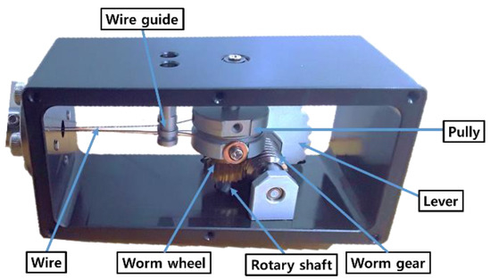
Figure 17.
Mechanism of proposed passive, hand-held bendable device.
We had previously [4] conducted a workspace analysis for TSA surgery. In the TSA, preprocessing was performed to remove some tissue and bone, thereby opening a pathway to the pituitary gland, as shown in Figure 18. Based on 3-D patient model, we have conducted to analyze the bendable device motion, as shown in Figure 19.
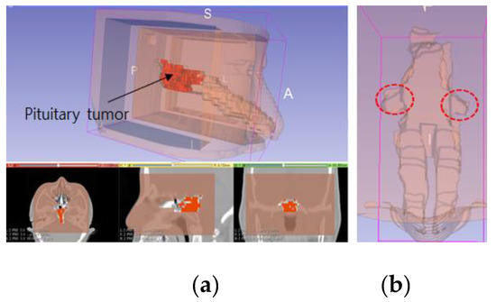
Figure 18.
Patient 3-D model, showing: (a) reconstruction of a patient model created using CT imagery; (b) blind spots which occur when using a rigid endoscope.
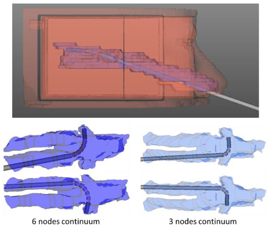
Figure 19.
Simulation used to determine bendable end-effector design parameters.
The position of the lever was decided by considering the surgeon′s posture when grasping the endoscope, as shown Figure 20. The reason for developing a hand-held type was that an endoscope needs to be frequently washed during surgery. To remove blood from the endoscope lens, the endoscope is taken out of the patient′s body and wiped with alcohol cotton or gauze—this is more easily done with a hand-held instrument.
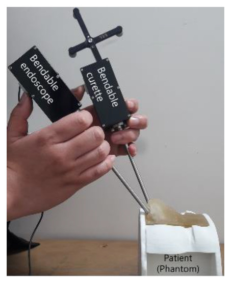
Figure 20.
Posture used for holding bendable devices.
The bending motion of the endoscope was achieved by turning the lever, as shown in Figure 21. A camera, with a 3.8 mm external diameter, capable of achieving high-definition (HD, 1080 × 720 pixels) image quality, was installed at the distal end of the mechanism. To achieve bending, a spring backbone was employed and the radius of curvature, bending angle, radius of cylinder and the length of the continuum module were designed according to the task-dependent requirements of TSA surgery. In our design, we fixed cylinder length at 1.1 mm and after analyzing the anatomical structure of the pathway from the nostril to the pituitary gland, the radius of curvature and bending angle were settled as 9.5 mm and 90°, respectively. Then, taking the geometry of the pathway and the diameter of the HD camera into account, the bendable device diameter was fixed at 5 mm. The length of the continuum mechanism was then obtained from the radius of curvature and bending angle.

Figure 21.
Proposed passive, hand-held type, bendable endoscope end-effector.
Then, for these given values, the number of nodes and the length of the spring were determined by using the design parameter determining method [6]. Figure 22 shows the flexible device structure, which was created by connecting several hollow cylinders, a spring backbone and wires inserted into the cylinders. The design parameters for the bendable endoscope are presented in Table 2 and the process used to measure the bending angle and radius of curvature have been depicted in Figure 23.
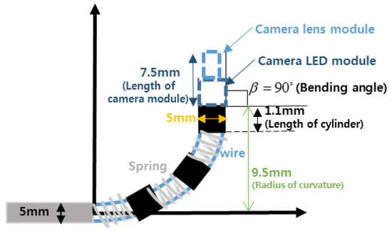
Figure 22.
Structure of the bendable device.

Table 2.
Bendable endoscope design parameters.
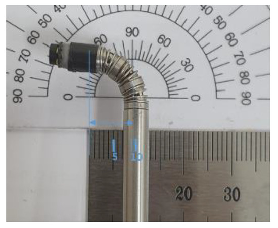
Figure 23.
Measurement of proposed bendable device bending angle and radius of curvature.
The tool used in transsphenoidal pituitary tumor removal surgery is called a “curette.” The proposed bendable surgical tool was built with a bending motion of 90°, as shown in Figure 24 and employed a ring curette as its end-effector. An optical marker was attached to the bendable surgical tool to enable real-time surgical tool tracking by the navigation system.

Figure 24.
Proposed passive, hand-held, bendable surgical tool curette end-effector.
4.2. Design of the Phantom
A phantom was constructed for use in our experiments. As the pathway between the nasal cavity and the pituitary is important in transsphenoidal pituitary surgery, a phantom was designed by considering the ICA and optic nerve positions, as shown in Figure 25 and was constructed using images of an actual patient with pituitary tumor (note: patient data used to make the phantom were not included in the training data). The phantom 3-D model was designed using the 3D slicer and then created with photosensitive resin, which was used because it does not deform even when a strong force is applied.
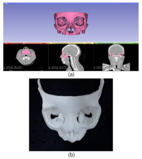
Figure 25.
3-D design and prototype of the phantom used for experiments: (a) phantom design using patient CTA data; (b) phantom TSA for surgery experiments.
5. Experimental Results
We conducted phantom experiments to test navigation system performance and to confirm both the accuracy of the U-Net-based segmentation and the feasibility of the developed bendable endoscope and surgical tool.
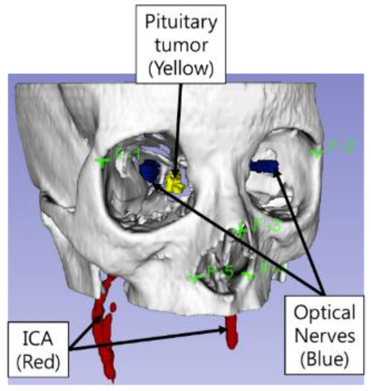
Measurement of fiducial registration error (FRE) and target registration error (TRE) has been accepted as an important procedure for checking registration accuracy [31]. Initially, using the phantom model, we measured the FRE and TRE of the surgical navigation system. The FRE measurement identifies errors by matching five image coordinate points to five phantom points, as shown in Figure 15. In our study, the TRE measurement was performed in relation to the F-6 point, which was selected as the point nearest the ICA, as shown in Figure 26. Automatic segmentation of the ICA was performed using U-net and the experimental environment for FRE and TRE measurement is shown in Figure 27.
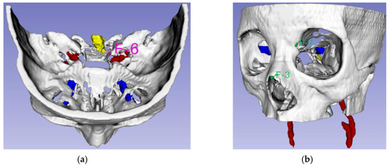
Figure 26.
Landmark points: (a) TRE experiment using landmark F-6 (Pink); (b) alarm warning system accuracy measurement experiment, using landmarks F-3 and F-7 (Green).
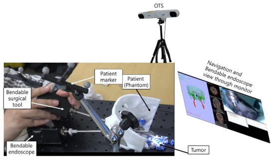
Figure 27.
Experimental setup used to test navigation system performance.
We performed a second experiment to quantify the similarity between the U-Net-based prediction and the manual segmentation of the ICAs and optical nerves. In this experiment, we employed the Jaccard index to find the similarity. The Jaccard index is a way to measure similarity between two datasets; it has a value between zero and one, showing one if the sets are identical and zero if there are no common elements between them.
Finally, the developed phantom was used to test whether the bendable surgical devices were appropriate for visualization of the target lesion and for specific tasks deep inside the brain.
Results from the navigation system FRE and TRE measurement experiments may be seen in Figure 28. As shown in the results of Figure 28, if the navigation system provided FRE and TRE within 0.5 mm, this would indicate precise surgery and would reduce the possibility of surgical instruments invading the ICAs or optic nerves during TSA surgery. Based on these guidelines, it can be seen, from Figure 28, that the use of the proposed navigation system with its alarm function would significantly reduce the risk of complications in patients undergoing TSA surgery.
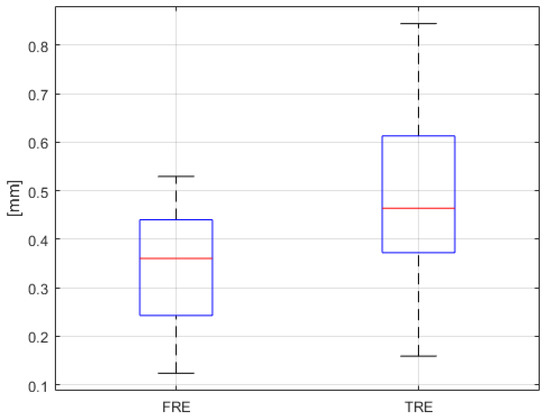
Figure 28.
FRE and TRE results (n = 25).
We were also able to conclude that the proposed surgical navigation system in this study was as or more accurate than conventional surgical navigation systems [32,33,34,35].
A warning system quantitative evaluation experiment was also conducted. As shown in Figure 29, distances between the bendable surgical tool and fiducial markers F-3 and F-7 were calculated by both the navigation system and as measured by the electromagnetic (EM) sensor (NDI Aurora). In this experiment, three EM sensors were attached—to the F-3 and F-7 fiducial markers in the phantom and to the distal end of the bendable surgical tool—with the surgical tool mounted on a motorized XYZ stage, to eliminate handshake errors during the experiment. In order to measure surgical navigation system alarm function error, the XYZ stage was moved at 1 mm intervals on each axis. Alarm function errors were measured for a total of 27 points. According to the experimental results depicted in Figure 30, we were able to confirm that the warning system had reasonable accuracy.
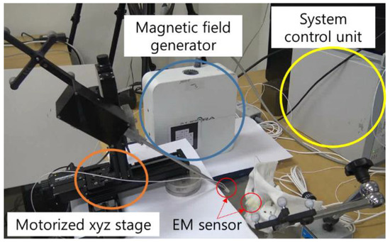
Figure 29.
EM sensors installed on the landmark F-3 marker and the bendable surgical tool end tip.
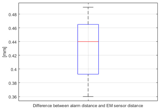
Figure 30.
Differences between the distances calculated by the navigation system alarm warning function and the actual distance as measured by the EM sensor (n = 27, for both F-3 and F-7).
The developed bendable endoscope and the surgical tool were inserted into the phantom′s nasal area, as shown in Figure 31. It was confirmed that all areas were identifiable by the endoscope and reachable using the surgical tool, which would not have been possible using a rigid endoscope.
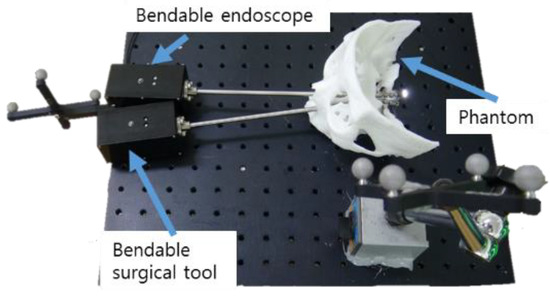
Figure 31.
Phantom experimental environment for the proposed bendable endoscope and bendable surgical tool.
In order to compare the rigid, straight-type endoscope and curette used in conventional TSA operations with the proposed bendable endoscope and surgical tool, a phantom-based mock tumor removal experiment was conducted. Figure 32 shows the experiment as conducted using rigid type endoscope and curette. The endoscope shown in Figure 32a was a Sinuscope Nasal Endoscope, with 0° and dimensions of 4 mm × 175 mm. The curette had an outer diameter of 4 mm and was manufactured by SHANZA. Tumors in the observation region could be removed, while those in its blind region could not be accessed, as they were not visible.
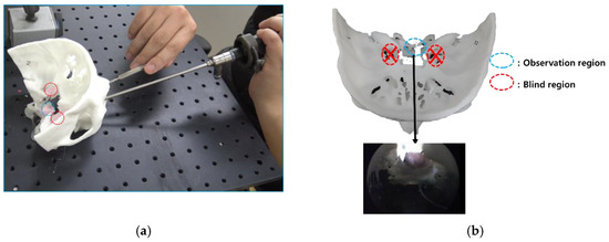
Figure 32.
Results of using conventional rigid endoscope and curette in phantom experiment. (a) experiment on the use of conventional straight endoscope and surgical tool.; (b) blind region caused by using a conventional straight endoscope and surgical tool.
The proposed bendable endoscope and bendable surgical tool, as well as the available observation region, are shown in Figure 33b. Here, tumors in the previously blind region could be seen and removed.
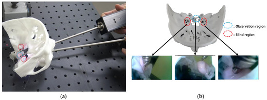
Figure 33.
Results for the proposed bendable endoscope and curette in phantom experiment. (a) experiment on the use of proposed bendable endoscope and bendable surgical tool.; (b) blind region removal using bendable endoscope and bendable surgical tool.
Finally, a phantom experiment using the surgical navigation system was conducted. Figure 34a illustrates the situation just before the surgical tool entered a nostril. At the same time, the end tip position of the surgical tool is shown by the red circle on the screen of the surgical navigation system in Figure 34b. We were able to confirm that there was very good synchronization between the navigation system and tool being operated, throughout serial surgical tool manipulations. The attached video clip demonstrates the performance of the navigation system, including its warning and tool tracking functions.

Figure 34.
Phantom experiment testing the surgical navigation system: (a) hardware setup; (b) navigation software.
6. Discussion
We examined the effectiveness of a surgical navigation system for transsphenoidal pituitary surgery developed by applying U-Net and bendable devices. Experimental results indicated that U-Net was useful for ICA and optical nerve segmentation by training CTA images. It was also noted that U-Net training results were not only applied to segmentation but also to the surgical navigation system for transsphenoidal pituitary surgery. By performing experiments, we demonstrated that applying the U-Net training results to surgical navigation, we could reduce the possibility of the surgical tool approaches vital organs. Reducing the possibility of surgical instruments accessing vital organs would reduce the complications during TSA surgery. We also showed that using our proposed bendable endoscope and bendable surgical tool, we could assist surgeons in easily checking previously blind regions. We had conducted experiments with other patients’ phantoms. The results for other patients’ phantom experiments are given in Appendix A.
However, there are more technical challenges to be overcome. The degree of bending in the proposed bendable device was not updated in the navigation system. To enhance this challenge, future work will involve incorporating a fiber Bragg grating sensor to measure the bending angle of the proposed bendable device, enabling the bending angle to be updated in the navigation system [36]. We also plan to apply the proposed navigation system and bendable devices to actual patient after receiving approval from Korean FDA.
Improving the quality of the camera in the bendable endoscope is another technical challenge. In this research, while a camera with HD resolution was used in the bendable endoscope, a higher quality bendable camera would make operations easier for the surgeon, through having better visibility.
In additional future work, we plan to apply a point cloud registration method, to avoid unnecessary contact between the patient and the matching tool, by using a 3-D scanner instead of PPR. In addition, we will add an augmented reality function to the navigation system, to overlay important organ locations on the camera view of the bendable endoscope.
Finally, in order to improve vital organ automatic segmentation performance, other neural networks—such as Nifty Net [37] or Deep Lab v3 [38]—will be tested in an effort to provide improved neural network prediction performance.
7. Conclusions
The objective of this study was to develop a U-Net-based segmentation algorithm for improved detection of patient vital organs in real-time. We believe that our results, which were achieved by combining U-Net with a surgical navigation system, will lead to reduced complications in TSA tumor removal surgery.
By performing phantom experiments, we demonstrated that the surgical robotic system developed by integrating the new, bendable surgical instruments with the U-Net-based surgical navigation system was useful for overcoming limitations of conventional TSA surgery.
Supplementary Materials
The following are available online at https://www.mdpi.com/2076-3417/9/24/5540/s1, Video S1: Surgical Navigation System for Transsphenoidal Pituitary Surgery Applying U-Net-Based Automatic Segmentation and Bendable Devices.
Author Contributions
H.-S.S., H.-S.Y. and S.L. contributed to the software and experiments, acquired the data, analyzed the data and wrote the paper; C.-K.H. contributed to paper review and editing; and B.-J.Y. provided supervision, project administration and review and editing support. All authors contributed to the paper. All authors have read and agreed to the published version of the manuscript.
Funding
This work was supported by the Technology Innovation Program (or the Industrial Strategic Technology Development Program—Artificial intelligence bio-robot medical convergence project), through Program 20001257 (Artificial intelligence algorithm-based vascular intervention robot system for reducing radiation exposure and achieving 0.5 mm accuracy). This Program is funded by the Ministry of Trade, Industry & Energy (MOTIE, Korea), the Ministry of Health & Welfare (MOHW), Ministry of Science and ICT (MSIT), Korea Evaluation Institute of Industrial Technology (KEIT). The work was performed by the ICT-based Medical Robotic Systems Team of Hanyang University, Department of Electronic Systems Engineering, which was supported by the BK21 Plus Program, funded by National Research Foundation of Korea (NRF).
Conflicts of Interest
The authors declare no conflict of interest.
Appendix A
The other patient′s phantom shown in Figure A1 was created with the image data of the different patient. This patient images were not included in U-Net training data. Based on the previous phantom experiments, we also conducted TRE, FRE, recall and precision measurement the same way. The results using the previous phantom came out similar to the experiment results conducted in the manuscript as shown in Figure A2, Figure A3 and Figure A4.
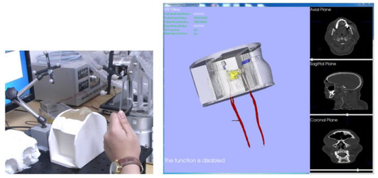
Figure A1.
Previous phantom experiment.
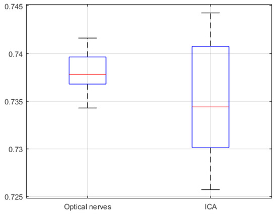
Figure A2.
Previous phantom experiment jaccard similarity of U-Net network (20 CTA image slices).
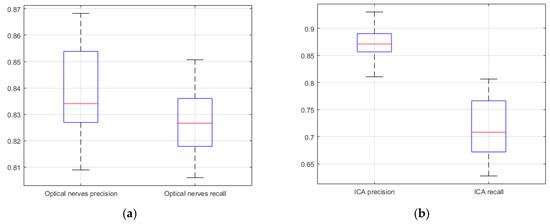
Figure A3.
Previous phantom experiment precision and recall of U-Net network (20 CTA image slices). (a) optical nerves precision and recall; (b) ICA precision and recall.
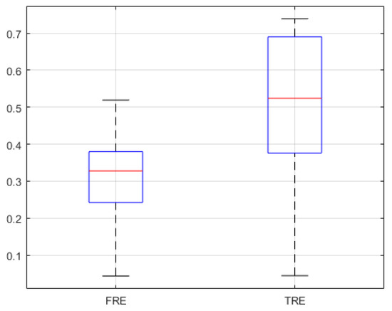
Figure A4.
FRE and TRE of previous phantom experiment (n = 25).
References
- Su, H.; Sandoval, J.; Vieyres, P.; Poisson, G.; Ferrigno, G.; De Momi, E. Safety-enhanced collaborative framework for tele-operated minimally invasive surgery using a 7-DOF torque-controlled robot. Int. J. Control. Autom. Syst. 2018, 16, 2915–2923. [Google Scholar] [CrossRef]
- Rotenberg, B.; Tam, S.; Ryu, W.H.A.; Duggal, N. Microscopic versus endoscopic pituitary surgery: A systematic review. Laryngoscope 2010, 120, 1292–1297. [Google Scholar] [CrossRef] [PubMed]
- Jaydeep, P.H. Robotic assisted minimally invasive surgery. J. Minimal Access Surg. 2009, 5, 1–7. [Google Scholar]
- Yoon, H.-S.; Song, H.-S. Preliminary study for Transsphenoidal pituitary surgery. In Proceedings of the Asian Conference on Computer Aided Surgery (ACCAS2017), Changhua, Taiwan, 26–28 November 2017. [Google Scholar]
- Velasquez, C.A.; Kim, Y.S.; Lendvay, T.S.; Hannaford, B.; Yoon, W.J. RAVEN Eyes Around the Instrument from Modular Axis Sharing. Int. J. Control. Autom. 2019, 17, 454–464. [Google Scholar] [CrossRef]
- Yoon, H.; Jeong, J.H.; Yi, B.-J. Image-guided dual master–slave robotic system for Maxillary sinus surgery. IEEE Trans. Robot. 2018, 34, 1098–1111. [Google Scholar] [CrossRef]
- Kwon, S.; Choi, W.; Ryu, G.; Kang, S.; Kim, K. Endoscopic Endonasal Skull Based Surgery System. In Proceedings of the 14th International Conference on Ubiquitous Robots and Ambient Intelligence, Jeju, Korea, 28 June–1 July 2017; pp. 544–545. [Google Scholar]
- Burgner, J.; Rucker, D.C.; Gilbert, H.B.; Swaney, P.J.; Russell, P.T.; Weaver, K.D.; Webster, R.J. A telerobotic system for Transnasal surgery. IEEE-ASME Trans. Mechatron. 2014, 19, 996–1006. [Google Scholar] [CrossRef]
- Jin, S.; Lee, S.K.; Lee, J.; Han, S. Kinematic Model and Real-Time Path Generator for a Wire-Driven Surgical Robot Arm with Articulated Joint Structure. Appl. Sci. 2019, 9, 4114. [Google Scholar] [CrossRef]
- He, Y.; Hu, Y.; Zhang, P.; Zhao, B.; Qi, X.; Zhang, J. Human–Robot Cooperative Control Based on Virtual Fixture in Robot-Assisted Endoscopic Sinus Surgery. Appl. Sci. 2019, 9, 1659. [Google Scholar] [CrossRef]
- Yoon, H.; Oh, S.M.; Jeong, J.H.; Lee, S.H.; Tae, K.; Koh, K.; Yi, B. Active Bending Endoscope Robot System for Navigation through Sinus Area. In Proceedings of the 2011 IEEE/RSJ International Conference on Intelligent Robots and Systems, San Francisco, CA, USA, 25–30 September 2011; pp. 967–972. [Google Scholar]
- Mark, M.; Levine, H.L.; Mester, S.J.; Schaitkin, B. Complications of endoscopic sinus surgery: Analysis of 2108 patients—Incidence and prevention. Laryngoscope 1994, 104, 1080–1083. [Google Scholar]
- Kong, X.; Duan, X.; Wang, Y. An integrated system for planning navigation and robotic assistance for mandible reconstruction surgery. Intell. Serv. Robot. 2016, 9, 113–121. [Google Scholar] [CrossRef]
- Lee, S.; Kim, J.Y.; Hong, J.; Baek, S.H.; Kim, S.Y. CT-based navigation system using a patient-specific instrument for Femoral component positioning: An experimental in vitro study with a Sawbone model. Yonsei Med. J. 2018, 59, 769–780. [Google Scholar] [CrossRef] [PubMed]
- Chung, G.B.; Kim, S.; Lee, S.G.; Yi, B.-J.; Kim, W.; Oh, S.M.; Kim, Y.S.; So, B.R.; Park, J.I.; Oh, S.H. An image-guided robotic surgery system for spinal fusion. Int. J. Control. Autom. Syst. 2006, 4, 30–41. [Google Scholar]
- Chung, J.; Kim, S.; Yi, B.-J.; Kim, Y.S. Cadaver study for spinal fusion surgery using an image-guided surgical robot system. Int. J. Control. Autom. Syst. 2010, 8, 564–573. [Google Scholar] [CrossRef]
- van Oosterom, M.N.; van der Poel, H.G.; Navab, N.; van de Velde, C.J.; van Leeuwen, F.W. Computer-assisted surgery: Virtual-and augmented-reality displays for navigation during urological interventions. Curr. Opin. Urol. 2018, 31, 205–213. [Google Scholar] [CrossRef]
- Chen, X.; Xu, L.; Wang, H.; Wang, F.; Wang, Q.; Kikinis, R. Development of a surgical navigation system based on 3D Slicer for intraoperative implant placement surgery. Med. Eng. Phys. 2017, 41, 81–89. [Google Scholar] [CrossRef]
- Hasan, W.; Daly, M.J.; Chan, H.H.L.; Qiu, J.; Irish, J.C. Intraoperative cone-beam CT-guided osteotomy navigation in mandible and maxilla surgery. Laryngoscope 2019, 1–7. [Google Scholar] [CrossRef]
- Forbes, K.; Karis, J.; White, W.L. Imaging of the pituitary gland. Barrow Q. 2002, 18, 9–19. [Google Scholar]
- Wang, C.; Zhao, Z.; Ren, Q.; Xu, Y.; Yu, Y. Dense U-net Based on Patch-Based Learning for Retinal Vessel Segmentation. Entropy 2019, 21, 168. [Google Scholar] [CrossRef]
- Xu, Y.; Mo, T.; Feng, Q.W.; Zhong, P.L.; Lai, M.D.; Chang, E.I.-C. Deep learning of feature representation with multiple instance learning for medical image analysis. In Proceedings of the 2014 IEEE International Conference on Acoustics, Speech and Signal Processing (ICASSP), Florence, Italy, 4–9 May 2014; pp. 1626–1630. [Google Scholar]
- Visentini-Scarzanella, M.; Sugiura, T.; Kaneko, T.; Koto, S. Deep monocular 3d reconstruction for assisted navigation in bronchoscopy. Int. J. Comput. Assist. Radiol. Surg. 2017, 12, 1089–1099. [Google Scholar] [CrossRef]
- Laina, I.; Rieke, N.; Rupprecht, C.; Vizcaíno, J.P.; Eslami, A.; Tombari, F.; Navab, N. Concurrent segmentation and localization for tracking of surgical instruments. In Medical Image Computing and Computer-Assisted Intervention—MICCAI 2017; Springer: Cham, Switzerland, 2017. [Google Scholar]
- Esfandiari, H.; Newell, R.; Anglin, C.; Street, J.; Hodgson, A.J. A deep learning framework for segmentation and pose estimation of pedicle screw implants based on C-arm fluoroscopy. Int. J. Comput. Assist. Radiol. Surg. 2018, 13, 1269–1282. [Google Scholar] [CrossRef]
- Ronneberger, O.; Fischer, P.; Brox, T. U-net: Convolutional networks for biomedical image segmentation. In Medical Image Computing and Computer-Assisted Intervention—MICCAI 2015; Springer: Cham, Switzerland, 2015; pp. 234–241. [Google Scholar]
- Litjens, G.; Kooi, T.; Bejnordi, B.E.; Setio, A.A.A.; Ciompi, F.; Ghafoorian, M.; Van Der Laak, J.A.; Van Ginneken, B.; Sánchez, C.I. A survey on deep learning in medical image analysis. arXiv 2017, arXiv:1702.05747. [Google Scholar] [CrossRef] [PubMed]
- Fausto, M.; Nassir, N.; Ahmad, S. V-net: Fully convolutional neural networks for volumetric medical image segmentation. In Proceedings of the 2016 Fourth International Conference on 3D Vision (3DV), Stanford, CA, USA, 25–28 October 2016; pp. 565–571. [Google Scholar]
- Badrinarayanan, V.; Kendall, A.; Cipolla, B. Segnet: A deep convolutional encoder-decoder architecture for image segmentation. IEEE Trans. Pattern Anal. Mach. Intell. 2017, 39, 2481–2495. [Google Scholar] [CrossRef]
- Knott, P.D.; Batra, P.S.; Butler, R.S.; Citardi, M.J. Contour and paired-point registration in a model for image-guided surgery. Laryngoscope 2006, 116, 1877–1881. [Google Scholar] [CrossRef] [PubMed]
- Fitzpatrick, J.M. Fiducial registration error and target registration error are uncorrelated. SPIE Med. Imaging Vis. Image Guided Proced. Model 2009, 7261. [Google Scholar] [CrossRef]
- Azarmehr, I.; Stokbro, K.; Bell, R.B.; Thygesen, T. Surgical navigation: A systematic review of indications, treatments, and outcomes in oral and maxillofacial surgery. J. Oral Maxillofac. Surg. 2017, 75, 1987–2005. [Google Scholar] [CrossRef] [PubMed]
- Shamir, R.R.; Joskowicz, L.; Shoshan, Y. Fiducial optimization for minimal target registration error in image-guided neurosurgery. IEEE Trans. Med. Imaging 2012, 31, 725–737. [Google Scholar] [CrossRef] [PubMed]
- West, J.B.; Fitzpatrick, J.M. The distribution of target registration error in rigid-body point-based registration. IEEE Trans. Med. Imaging 2001, 20, 917–927. [Google Scholar]
- Qin, C.; Cao, Z.; Fan, S.; Wu, Y.; Sun, Y.; Politis, C.; Wang, C.; Chen, X. An oral and maxillofacial navigation system for implant placement with automatic identification of fiducial points. Int. J. Comput. Assist. Radiol. Surg. 2019, 14, 281–289. [Google Scholar] [CrossRef]
- Xue, R.; Ren, B.; Huang, J.; Yan, Z.; Du, Z. Design and Evaluation of FBG-Based Tension Sensor in Laparoscope Surgical Robots. Sensors 2018, 18, 2067. [Google Scholar] [CrossRef]
- Gibson, E.; Li, W.; Sudre, C.; Fidon, L.; Shakir, D.I.; Wang, G.; Eaton-Rosen, Z.; Gray, R.; Doel, T.; Hu, Y.; et al. Niftynet: A deep-learning platform for medical imaging. Comput. Methods Programs Biomed. 2018, 158, 113–122. [Google Scholar] [CrossRef]
- Chen, L.C.; Papandreou, G.; Schro, F.; Adam, H. Rethinking Atrous Convolution for Semantic Image Segmentation. arXiv 2017, arXiv:1706.05587. [Google Scholar]
© 2019 by the authors. Licensee MDPI, Basel, Switzerland. This article is an open access article distributed under the terms and conditions of the Creative Commons Attribution (CC BY) license (http://creativecommons.org/licenses/by/4.0/).
