Whole-Body Motion Planning for a Six-Legged Robot Walking on Rugged Terrain

1
School of Mechanical Engineering and Automation, Northeastern University, Shenyang 110819, China
2
State Key Laboratory of Robotics and System, Harbin Institute of Technology, Harbin 150001, China
*
Author to whom correspondence should be addressed.
Appl. Sci. 2019, 9(24), 5284; https://doi.org/10.3390/app9245284
Submission received: 23 October 2019
/
Revised: 24 November 2019
/
Accepted: 29 November 2019
/
Published: 4 December 2019
(This article belongs to the Special Issue Optimization of Motion Planning and Control for Automatic Machines, Robots and Multibody Systems)
Abstract
:Whole-body motion planning is a key ability for legged robots, which allows for the generation of terrain adaptive behaviors and thereby improved mobility in complex environment. To this end, this paper addresses the issue of terrain geometry based whole-body motion planning for a six-legged robot over a rugged terrain. The whole-body planning is decomposed into two sub-tasks: leg support and swing. For leg support planning, the target pose of the robot torso in a walking step is first found by maximizing the stability margin at the moment of support-swing transition and matching the orientation of the support polygon formed by target footholds. Then, the torso and thereby the leg support trajectories are generated using cubic spline interpolation and transferred into joint space through inverse kinematics. In terms of leg swing planning, the trajectories in a walking step are generated by solving an optimal problem that satisfies three constraints and a bioinspired objective function. The proposed whole-body motion planning strategies are implemented with a simulation and a real-world six-legged robot, and the results show that stable and collision-free motions can be produced for the robot over rugged terrains.
1. Introduction
Over the last few decades, six-legged robots seem to have received much attention for several reasons. First, six-legged robots are useful scientific tools that can be employed to investigate complicated biological mechanisms such as biomechanics and neuroscience, on the side of biology, and planning and control algorithms, on the side of robotics [1,2,3,4,5]. Second, six-legged robots can be used in many application scenarios like search and rescue [6,7]. As a result, to date a variety of six-legged robotic platforms have been constructed.
Locomotion in complex terrain is one of the fundamental topics for legged robotic research. Broadly, various strategies adopted in the literature may be categorized into different approaches. The first is an executing-reacting approach which means the robot executes its predefined motions first then adapts to terrain changes through reactive behaviors. An example in this approach is the RHex-like robots which employ special-designed curved legs to achieve robust locomotion in rugged terrains [8,9]. Such designs are simple, reliable and able to mechanically adapt to a certain degree of terrain roughness. Further, a number of legged robots integrate various control strategies to actively adapt to rugged terrain. Impedance control and posture control are two commonly used strategies in this line [6,10,11]. A number of six-legged robots also integrate different reflexes, including stretch reflex, searching reflex, stepping reflex, and elevator reflex, to react to obstacles or holes during stepping motions, thereby increasing the robot mobility on unstructured terrain [6,11,12,13]. An alternate approach is a planning–reacting paradigm, which means reasonable motion would be deliberately planned before robot executing and additional terrain uncertainty would be overcome by reactive motion control. For example, Lee and Song propose a Bezier curves based path planning method, which enables a quadruped robot to generate a feasible path in an obstacle-strewn environment [13]. Likewise, in [14], the authors label the obstacles as accessible or inaccessible regions and then plan path for a legged robot by employing the potential field algorithm. A recent example is the BigDog quadruped robot, in which an optimal path was found using 2D cost map and A ∗ algorithm [15]. On this basis, the planned path is commanded to be followed using robustly reactive motion controllers. With these approaches, robotic legged locomotion can be accomplished over moderately rugged terrains.
Similar to human rock-climbing, whereby the climber has to carefully plan his/her foot/hand motions according to the rock wall and his/her capability, over severe rugged terrains, deliberate whole-body motion planning has to be conducted for legged robots. In addition, careful whole-body motion planning is also helpful for legged robots to address the limitations of its own kinematics, for example, a better kinematic margin for subsequent robot movements. In this line, Belter et al. proposes two-layered whole-body motion planning for the six-legged robot Messor according to surrounding environment models. The authors use a higher-level planner, which uses A ∗ algorithm to plan a path, and a lower-level planner, in which the guided-RRT is applied to find feasible motion trajectories of 18-dimensional joint space [7]. Kalakrishnan et al. employs a combination method of planning and optimization for a quadruped robot walking dynamically over rugged terrains [16,17]. The trajectory of the robot CoG is generated by a series of quintic spline curves. The trajectory of the robot torso is given by optimizing squared accelerations along the trajectory based on the zero-moment point (ZMP) stability criterion. The foot trajectories are initially generated according to the convex hull of the terrain from the start location and the target location using piece-wise quintic splines, and then subsequently optimized to eliminate potential shin or knee collisions. Vernaza et al. decompose the planning problem of a quadrupedal robot into two main phases, namely an initial global planning phase, which searches for feasible footstep trajectories by the use of the R* search algorithm, and an execution phase, which dynamically generates complete joint trajectories according to the planned footstep trajectories [18]. All these attempts have demonstrated the effectiveness of appropriately generating whole-body motions for legged robots and thereby increased the robot mobility on unstructured terrain.
In this paper, we focus on the issue of terrain geometry based whole-body motion planning for a six-legged robot walking on rugged terrain. In our method, leg support and swing are planned respectively. For leg support, maximizing the stability margin of support-swing transition is mainly considered, which is distinct from the existing method. In terms of leg swing planning, the problem was formulated as an optimal control procedure that satisfies a series of locomotion task terms while minimizing a biologically-based objective function. To better concentrate on the motion planning problem, it is assumed that the terrain has been already obtained in advance and described by a 2.5D grid-type digital elevation model (DEM). DEM provides a compact representation, allows for efficient processing, and avoids the complexity of using full three-dimensional maps. The remainder of the paper is organized as follows: Section 2 presents a whole-body motion planning method for six-legged robots, including support and swing planning. Then, the results of both the simulation and experiment are presented and analyzed in Section 3, followed by a necessary interpretation of the observed behaviors. Finally, Section 4 concludes with a brief summary of the paper.
2. Methods
Whole-body motion planning is crucial to achieve mobile and robust robot walking. For a six-legged robot, the whole-body motion can be divided into two parts: one is that some of the six legs support and propel the torso to achieve corresponding movements on the ground; the other is that the rest legs take the torso as a floating base and perform swing movements in the air. This section first analyzes the stability of six-legged robotic walking, then introduces the motion planning methods of support and swing, respectively.
2.1. Stability Analysis of Six-Legged Robotic Walking
Stability is the premise of effective motion of a robot. It is necessary to ensure sufficient stability margin in the whole process of six-legged robotic walking [19]. That is to say, the center of gravity (CoG) of the robot should be always in the horizontal projection of the supporting polygon formed by supporting legs at the beginning, during moving and at the end of each waking step. Figure 1 illustrates an example of tripod gait with a duty cycle of 0.5. In this example, a, b, and c are the supporting points of current supporting legs, Δabc is the formed supporting triangle; d, e, and f are the target supporting points for the following step of the robot, Δdef is the supporting triangle for the following step; the shaded area is the overlap of Δabc and Δdef; O1, O2, and O3 are the centers of the maximum inner circle of Δabc, Δdef and the overlap, respectively. Without loss of generality, it is assumed that, at the beginning, the horizontal projection of the robot CoG is at the incenter O1 of Δabc. When the six-legged robot starts to move, the projection of the robot CoG on the horizontal plane gradually moves along the forward direction from O1 until the walking is completed. According to the definition of robot stability [19], in order to ensure the stability of the robot in the whole walking process, two conditions need to be satisfied: 1. Before the swing legs contact the ground, the projection of the robot CoG must be within Δabc; 2. After the swing legs contact the ground, the projection of the robot CoG must be within Δdef. This requires that the projection of the robot CoG on the horizontal plane falls in the overlap of the two triangles at the moment of support-swing transition. Otherwise, when the supporting leg changes, the robot will become unstable, thereby leading to failure of the whole walking task or even damage to the robot hardware. Furthermore, in order to ensure that the robot can maintain a large stability margin at the moment of support-swing transition, it is better that the horizontal projection of the robot CoG falls at the incenter O2 of the overlap at the moment of transition.
According to the above analysis, the motion of the robot torso in a walking step can be divided into two stages: as illustrated in Figure 1, the first stage is the movement from O1 to O2, and the second stage is from O2 to O3. This paper mainly discusses the planning problem of the first stage, which is the key point to ensure stable walking. The movement from O2 to O3 is implemented via control adjustment which is out of the scope of this paper.
2.2. Support Planning
While walking in rugged terrain, the spatial distribution of footholds for support legs is complex and various, probably leading to inclination and destabilization of the robot. Therefore, it is necessary to plan, in advance, the movements of the robot torso and thereby the movement of each supporting leg. In addition, proper motion is also helpful to enhance the stability and terrain adaptability of the robot. In this context, the six-dimensional torso pose would be considered. The overall process of support planning is demonstrated in Figure 2.
2.2.1. Torso Horizontal Position and Height
For a walking step of the six-legged robot, one key point of motion planning is to find a proper target state that maximizes the stability margin of the robot, then the robot can move from current state to the target state. According to geometric knowledge and the definition of stability [19], when the projection of the robot CoG is exactly at the center of the maximum inner circle of the support polygon formed by target footholds, the robot can obtain the maximum stability margin. In order to derive the incenter O2 (Xr, Yr) of the support polygon, as illustrated in Figure 3, the following steps are adopted:
Step 1: Arbitrarily select a point S (Xs, Ys) in the polygon as the incenter to start calculation. In this paper, we choose the midpoint of two vertices of a polygon that are not adjacent to each other.
Step 2: Calculate the shortest distance from the incenter S to each side of the supporting polygon and the position of the corresponding points. The two points closest to each other were determined and recorded as A (XA, YA), distance LA, B (XB, YB) and distance LB, respectively.
Step 3: Select a new point C (XC, YC) according to the following rules: if A, B and S are collinear, then C = A; if A, B and S are not collinear, then choose
Step 4: Set the step size factor a, and take a point S’ (Xs, Ys) on the extension line of CS as the new center of the calculation circle according to the following rules, namely:
Step 5: Repeat Step 2 with the newly calculated center S’, and compare the calculated minimum distance L’ with LA. If the value of L’ increases, continue Steps 3 and 4; otherwise, the step factor is decreased to 0.5a and recalculate the incenter with Equation (2). With cyclic calculation of the above steps, the incenter O2 (Xr, Yr) of the maximum inner circle of the supporting polygon can be obtained. In this regard, the planning task of support legs is to propel the horizontal position of the torso from the current O1 to the incenter O2 (Xr, Yr) of the support polygon.
In terms of the torso height, the purpose is to keep a certain distance from the ground. In this paper, it is prescribed that the robot CoG and the incennter of the supporting polygon are always maintained at a certain height h. This can prevent the collision between the robot and the ground simply and effectively.
2.2.2. Torso Posture
The so-called torso posture mainly refers to the inclination of the body in space, which can be expressed by yaw α, pitch β and roll γ, respectively. Among them, the yaw α is determined by the robot’s moving direction, so the posture planning in this section is mainly the pitch β and roll γ of the torso. In order to obtain the target posture of the robot torso, the following steps are adopted:
Step 1: Derive the target supporting polygon by fitting the target footholds and calculate the pitch βSP and the roll γSP of the supporting polygon;
Step 2: Calculate the desired pitch βd and roll γd according to the following formula
where, βa and γa are the current inclination parameters of the robot torso collected by the pose sensor.
So far, we have obtained the initial and termination values of the six-dimensional motion of the robot torso. Since the torso is passive and has no active driving ability, its movement is completely propelled by supporting legs. Therefore, the torso motion needs to be transferred to the joint space of each supporting leg of the robot. For this purpose, N path points are collected from all directions of the torso, and then the path points of each supporting leg joint are obtained by means of kinematic transformation and calculation. Next, these path points are interpolated by cubic spline curve to obtain smooth joint trajectories. Let be the corresponding path points of each supporting leg joint, where l is the number of supporting legs, j = 1, 2 and 3 are the three joints of a certain supporting leg, and N is the number of path points. For any joint j of a supporting leg l, the cubic spline curve S is constructed to meet the path points and continuity conditions, namely:
where ti is the motion time variable corresponding to each path point. In addition, in order to solve the equation, the boundary conditions are further set up:
With a total of 4(N − 1) boundary conditions, the unique joint interpolation trajectories can be obtained.
2.3. Swing Planning
Swing occurs when the legs take the torso as a floating base and perform swing movements in the air, as depicted in Figure 4a. Under this circumstance, each swing leg can be considered as a three-axis manipulator. For such a configuration, energy-optimal collision-free motion planning is usually considered in the literature [20]. Alternatively, it is also adopted to integrate the moving principles of human or animal limbs into the motion planning of robotic legs. This could be advantageous in terms of achieving a natural and graceful leg swing. In this context, the swing planning is formulated as an optimization problem. The objective function of the generated optimization problem is established upon the underlying optimality criteria of animal locomotion. In addition, three types of constraint are considered, namely terrain clearance, initial/final constraint, and physical limit. A direct transcription method called the Gauss pseudospectral method (GPM), which is characterized by fast convergence, is adopted to solve the optimization problem. The entire swing planning procedure is summarized in Figure 4b. More details about swing planning can be obtained in our publication [21].
3. Results
3.1. Simulation
To validate the whole-body planning method, a simulation platform, consisting of a patch of rugged terrain and a six-legged robot, is built, as shown in Figure 5. The size of the rugged part is 400 × 800 mm. The maximum peak height is about 178 mm (height of the robot torso in initial state is roughly 170 mm). The black balls in the figure correspond to rotational joints of the robot. In this simulation, the robot is commanded to walk across the rugged terrain patch along a given walking path using the alternating-tripod gait [7,22,23,24].
To implement the walking simulation, a set of footholds are given manually, according to the given walking path as well as the current position and pose of the robot. The green balls in Figure 5 correspond to those given footholds. The maximum foothold height is 80 mm while the minimum height is roughly 10 mm. On this basis, the proposed planning method is employed to produce whole-body motion of the six-legged robot. In specific, for each walking step, the six-dimensional trajectories of the robot torso are planned according to the strategies in Section 2.2. The results are shown in Figure 6. It can be seen from the torso pitch curve that the robot first performs the hill-climbing movement and then the down-hill movement, which is also consistent with the given terrain geometry. From the torso roll curve, it can be seen that obvious oscillations occur in the middle of the walking process, and this is mainly due to the larger height differences of the given footholds in these walking steps. In addition, the relatively large change in the lateral direction of the robot torso is to maximize the stability margin of the robot. The foot trajectories of swing legs are generated using the scheme in Section 2.3. After that, the planned trajectories are converted to the joint space through inverse kinematics, as shown in Figure 5 and Figure 7 which depict the consecutive snapshots of the robot walking. By monitoring the joint positions in simulation, it can be seen that the robot maintains a proper kinematic margin during walking, thereby ensuring a good flexibility and ample room for the adjustment of robot states.
3.2. Experimental Study
This section discusses the experimental verification of the proposed planning method with our six-legged robotic platform (as illustrated in Figure 8). Specific design and control details about the robot are available in references [5,21,25]. The experimental setup is illustrated in Figure 9. The robot is commanded to walk through the specified terrain with a certain initial state. The terrain, which is 3D printed by PLA material, is irregular wave shape. Its size is about 850 × 800 mm (width × length). The maximum peak height is about 160 mm. According to our experimental observations, for the terrain with small obstacles shown in Figure 8, the irregularities can be overcome using fixed motions and reactive control. However, the robot would capsize if the fixed motions are still used for the irregular wave terrain in Figure 9. This is because, severe nonuniform distribution of foot forces and foot slippages would occur when the robot places its feet onto the irregular peaks. As a result, it is necessary to plan the whole-body motion of the robot according to the terrain in advance.
In the experimental procedure, both the robot and the 3D-printed terrain are placed at the designated locations, and as a result, the terrain information is known for the robot. In addition, a set of footholds are given manually according to the terrain geometry. The maximum foothold height is roughly 19 mm while the minimum height is about 148 mm. Under this circumstance, the proposed planning method is used to produce and calculate the movements of the torso and legs. Then the joint trajectories are obtained by inverse kinematics. In addition, motion control is crucial for the experiment implementation. Various robot control methods have been proposed, effectively improving the performance of robots [26,27,28]. In this experiment, our aim is to validate the proposed motion planning method, as a result, each joint is just PD controlled to ensure accurate leg movements, and impedance control is added in each leg-end to deal with ground reaction force. Snapshots of the real-world robot walking over irregular wave terrain are shown in Figure 10. Experiments show that the robot successfully traverses the given terrain.
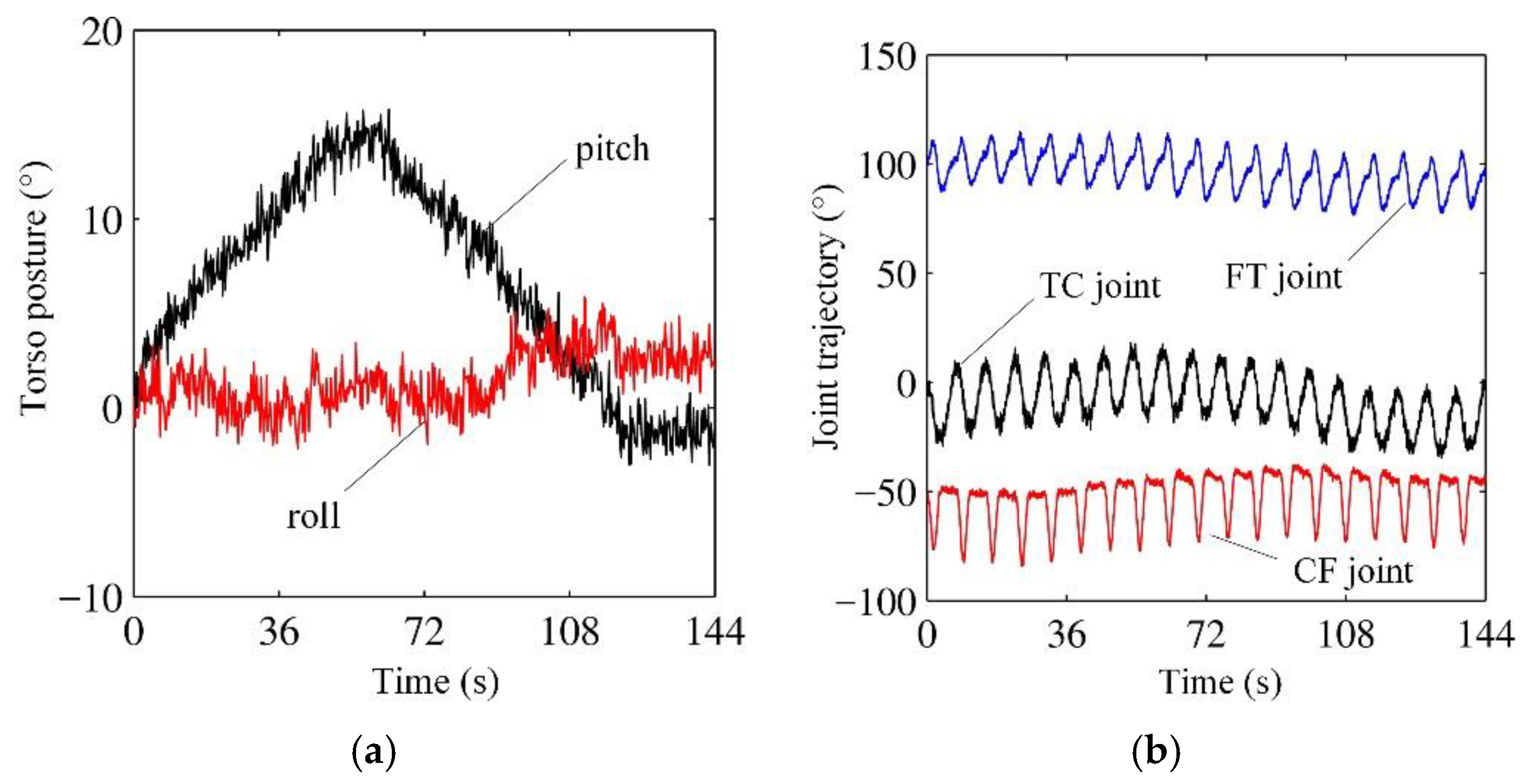
Figure 11 shows the trajectory curves of the torso and leg joints during the experiment. The walking details can be learnt from the trend of these curves. Specifically, as shown in Figure 11a, the pitch angle of the robot torso first presents an increasing trend, which corresponds to the initial climbing motion of the robot. Then, the pitch angle shows a decreasing trend, but still maintains positive value, indicating that the front leg or middle leg of the robot has reached the flat terrain shown in Figure 9. The pitch angle becomes roughly 0, indicating that the robot has completely crossed the wave terrain. Small changes of the torso rolling reflect the adjusting effect of the robot during walking.
Figure 11b shows variations of the joint angles in the left foreleg of the robot. Overall, the three joints display a periodic characteristic, which is consistent with the reciprocating motion of legged locomotion. In addition, the trajectories are also different in each walking cycle, which is, on the one hand, due to the terrain irregularity and thereby the different step lengths of each step. On the other hand, the adjustments of the control system to each joint are also different in the course of motion. Through the walking experiment on irregular wave terrain, the adaptability of the robot on complex terrain is further demonstrated, and the effectiveness of the motion planning mentioned above is illustrated.
4. Conclusions
In this work, the whole-body motion planning of a six-legged robot over rugged terrain is explored. The planning problem is decomposed into support motion and swing motion. For support motion, stability maximization and orientation matching are mainly considered to search for the target pose of the robot torso, and then the motion in each support leg is generated using cubic spline interpolation. In terms of swing motion, the problem was transferred into an optimization problem, which minimizes a bioinspired objective function and satisfies three constraints. Both simulations and real-world experiments are conducted to validate the proposed whole-body motion planning method. In the future work, we will focus on dynamic control schemes of legs to enhance the terrain adaptivity of the robot.
Author Contributions
Conceptualization, J.C. and J.Z.; methodology, J.C., F.G. and C.H.; validation, J.C. and J.Z.; formal analysis, J.C., F.G., C.H. and J.Z.; writing—original draft preparation, J.C., F.G. and C.H.; writing—review and editing, J.C., F.G., C.H. and J.Z.
Funding
This work was supported by National Natural Science Foundation of China (Grant No. 51805074), State Key Laboratory of Robotics and System (HIT) (Grant No. SKLRS-2018-KF-02), China postdoctoral Science Foundation (Grant no. 2018M631799 and 2019T120213), Fundamental Research Funds for the Central Universities (Grant No. N170303007), Natural Science Foundation of Liaoning Province (2019-BS-090) and postdoctoral Science Foundation of Northeastern University (Grant No. 20180311).
Conflicts of Interest
The authors declare no conflict of interest.
References
- Floreano, D.; Ijspeert, A.J.; Schaal, S. Robotics and Neuroscience. Curr. Biol. 2014, 24, R910–R920. [Google Scholar] [CrossRef] [PubMed] [Green Version]
- Jackson, A. Neuroscience: Brain-controlled robot grabs attention. Nature 2012, 485, 317–318. [Google Scholar] [CrossRef] [PubMed]
- Andrada, E.; Mämpel, J.; Schmidt, A.; Fischer, M.; Karguth, A.; Witte, H. From biomechanics of rats’ inclined locomotion to a climbing robot. Int. J. Des. Nat. Ecodynamics 2013, 8, 192–212. [Google Scholar] [CrossRef] [Green Version]
- Tugcu, M.; Wang, X.; Hunter, J.E.; Phillips, J.; Noelle, D.; Wilkes, D.M. A computational Neuroscience model of working memory with application to robot perceptual learning. In Proceedings of the Third IASTED International Conference on Computational Intelligence (CI), Banff, AB, Canada, 2–4 July 2007. [Google Scholar]
- Zhang, H.; Liu, Y.; Zhao, J.; Chen, J.; Yan, J. Development of a bionic hexapod robot for walking on unstructured terrain. J. Bionic Eng. 2014, 11, 176–187. [Google Scholar] [CrossRef]
- Stelzer, A.; Hirschmüller, H.; Görner, M. Stereo-vision-based navigation of a six-legged walking robot in unknown rough terrain. Int. J. Robot. Res. 2012, 31, 381–402. [Google Scholar] [CrossRef] [Green Version]
- Belter, D.; Łabęcki, P.; Skrzypczyński, P. Adaptive Motion Planning for Autonomous Rough Terrain Traversal with a Walking Robot. J. Field Robot. 2016, 33, 337–370. [Google Scholar] [CrossRef]
- Saranli, U.; Buehler, M.; Koditschek, D.E. RHex: A Simple and Highly Mobile Hexapod Robot. Int. J. Robot. Res. 2001, 20, 616–631. [Google Scholar] [CrossRef] [Green Version]
- Altendorfer, R.; Moore, N.; Komsuoglu, H.; Buehler, M.; Brown Jr, H.B.; McMordie, D.; Saranli, U.; Full, R.; Koditschek, D.E. RHex: A biologically inspired hexapod runner. Auton. Robots 2001, 11, 207–213. [Google Scholar] [CrossRef] [Green Version]
- Görner, M. The DLR Crawler: Evaluation of gaits and control of an actively compliant six-legged walking robot. Ind. Robot Int. J. 2009, 36, 344–351. [Google Scholar] [CrossRef]
- Bartsch, S.; Birnschein, T.; Römmermann, M.; Hilljegerdes, J.; Kühn, D.; Kirchner, F. Development of the six-legged walking and climbing robot SpaceClimber. J. Field Robot. 2012, 29, 506–532. [Google Scholar] [CrossRef]
- Albiez, J.C.; Luksch, T.; Berns, K.; Dillmann, R. Reactive reflex-based control for a four-legged walking machine. Robot. Auton. Syst. 2003, 44, 181–189. [Google Scholar] [CrossRef]
- Lee, J.-K.; Song, S.-M. Path planning and gait of walking machine in an obstacle-strewn environment. J. Robot. Syst. 1991, 8, 801–827. [Google Scholar] [CrossRef]
- Bai, S.; Low, K.H. Terrain evaluation and its application to path planning for walking machines. Adv. Robot. 2001, 15, 729–748. [Google Scholar] [CrossRef] [Green Version]
- Wooden, D.; Malchano, M.; Blankespoor, K.; Howardy, A.; Rizzi, A.A.; Raibert, M. Autonomous navigation for BigDog. In Proceedings of the 2010 IEEE International Conference on Robotics and Automation, Anchorage, Alaska, 4–8 May 2010; pp. 4736–4741. [Google Scholar]
- Kalakrishnan, M.; Buchli, J.; Pastor, P.; Mistry, M.; Schaal, S. Fast, robust quadruped locomotion over challenging terrain. In Proceedings of the IEEE International Conference on Robotics and Automation, Anchorage, Alaska, 4–8 May 2010; pp. 2665–2670. [Google Scholar]
- Kalakrishnan, M.; Buchli, J.; Pastor, P.; Mistry, M.; Schaal, S. Learning, planning, and control for quadruped locomotion over challenging terrain. Int. J. Robot. Res. 2010, 30, 236–258. [Google Scholar] [CrossRef]
- Vernaza, P.; Likhachev, M.; Bhattacharya, S.; Chitta, S.; Kushleyev, A.; Lee, D.D. Search-based planning for a legged robot over rough terrain. In Proceedings of the IEEE International Conference on Robotics and Automation, Kobe, Japan, 12–17 May 2009; pp. 2380–2387. [Google Scholar]
- McGhee, R.B.; Frank, A.A. On the stability properties of quadruped creeping gaits. Math. Biosci. 1968, 3, 331–351. [Google Scholar] [CrossRef]
- Zhao, Y.; Wang, Y.; Zhou, M.; Wu, J. Energy-Optimal Collision-Free Motion Planning for Multiaxis Motion Systems: An Alternating Quadratic Programming Approach. IEEE Trans. Autom. Sci. Eng. 2019, 16, 327–338. [Google Scholar] [CrossRef]
- Chen, J.; Liu, Y.; Zhao, J.; Zhang, H.; Jin, H. Biomimetic Design and Optimal Swing of a Hexapod Robot Leg. J. Bionic Eng. 2014, 11, 26–35. [Google Scholar] [CrossRef]
- Bjelonic, M.; Kottege, N.; Homberger, T.; Borges, P.; Beckerle, P.; Chli, M. Weaver: Hexapod robot for autonomous navigation on unstructured terrain. J. Field Robot. 2018, 35, 1063–1079. [Google Scholar] [CrossRef]
- Sun, Q.; Gao, F.; Chen, X. Towards dynamic alternating tripod trotting of a pony-sized hexapod robot for disaster rescuing based on multi-modal impedance control. Robotica 2018, 36, 1048–1076. [Google Scholar] [CrossRef]
- de Santos, P.G.; Garcia, E.; Ponticelli, R.; Armada, M. Minimizing Energy Consumption in Hexapod Robots. Adv. Robot. 2009, 23, 681–704. [Google Scholar] [CrossRef] [Green Version]
- Chen, J.; Liang, Z.; Zhu, Y.; Zhao, J.J.J.o.B.E. Improving Kinematic Flexibility and Walking Performance of a Six-legged Robot by Rationally Designing Leg Morphology. J. Bionic Eng. 2019, 16, 608–620. [Google Scholar] [CrossRef]
- Li, S.; Zhou, M.; Luo, X. Modified Primal-Dual Neural Networks for Motion Control of Redundant Manipulators With Dynamic Rejection of Harmonic Noises. IEEE Trans. Neural Netw. Learn. Syst. 2018, 29, 4791–4801. [Google Scholar] [CrossRef] [PubMed]
- Sun, P.; Yu, Z. Tracking control for a cushion robot based on fuzzy path planning with safe angular velocity. IEEE/CAA J. Autom. Sin. 2017, 4, 610–619. [Google Scholar] [CrossRef]
- Nakhaeinia, D.; Payeur, P.; Laganiere, R. A Mode-Switching Motion Control System for Reactive Interaction and Surface Following Using Industrial Robots. IEEE/CAA J. Autom. Sin. 2018, 5, 670–682. [Google Scholar] [CrossRef]
Figure 1.
Schematic of stability of six-legged robotic walking with tripod gait.
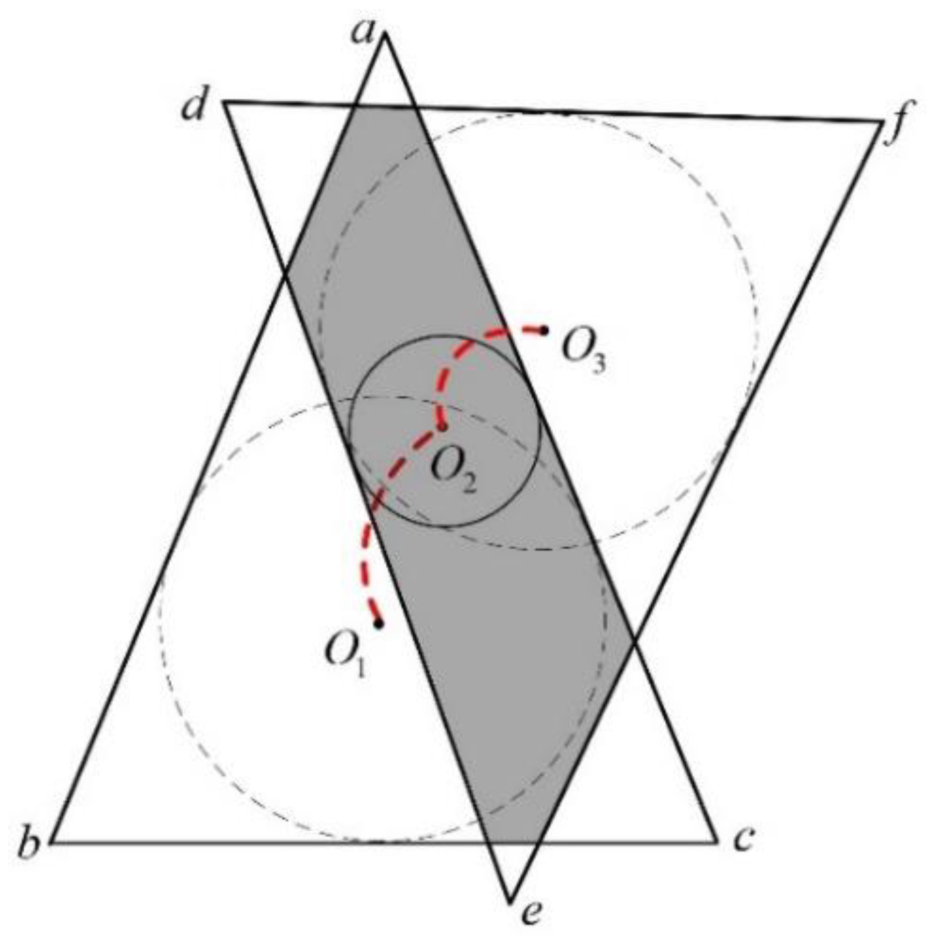
Figure 2.
Schematic of the support planning process.
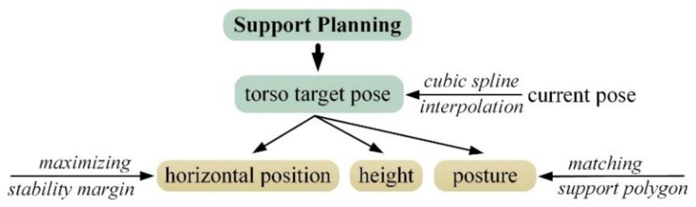
Figure 3.
Flow diagram to find the incenter of the support polygon.
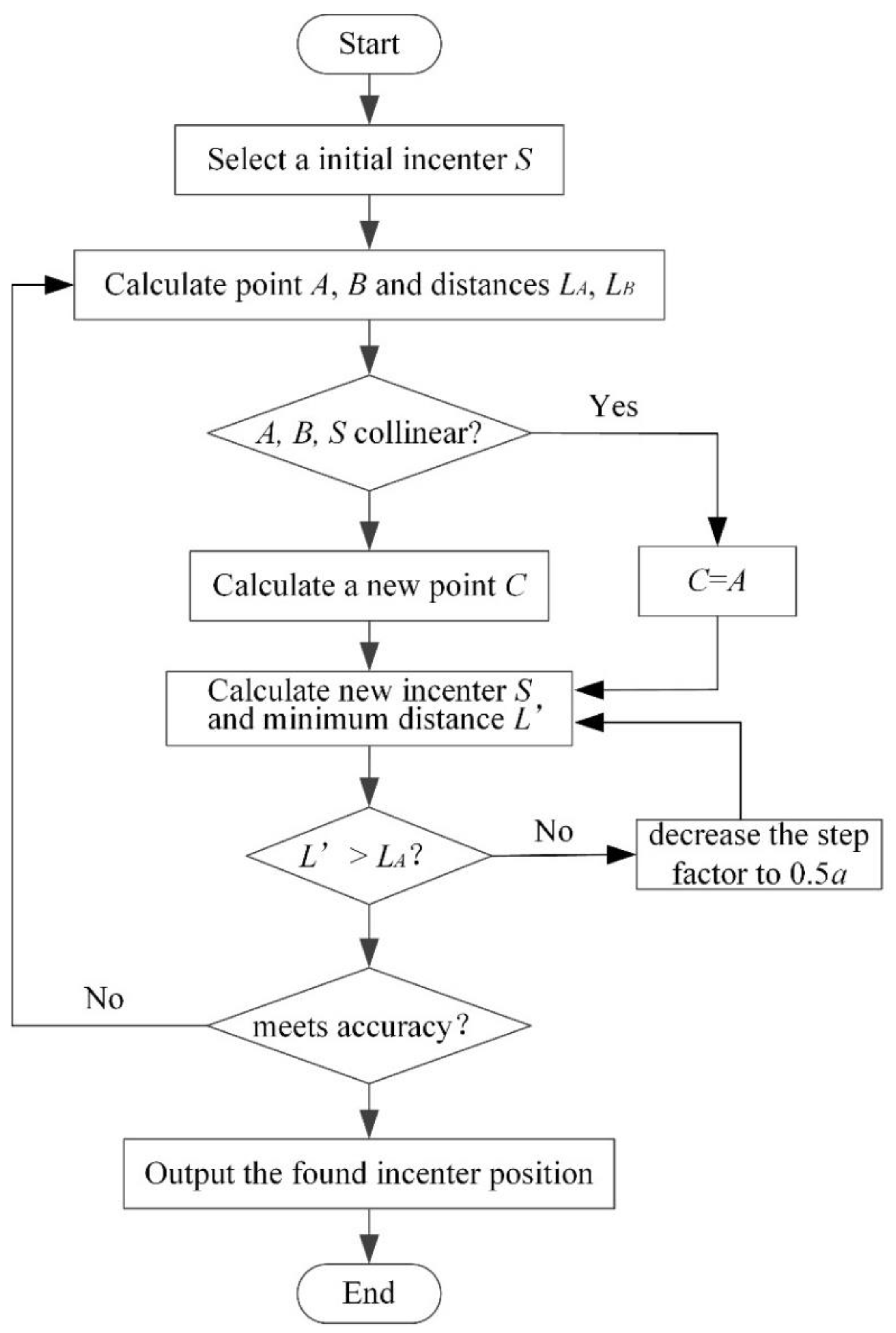
Figure 4.
Swing planning of the hexapod robot. (a) Schematic of leg swing. (b) Schematic of the swing planning process.
Figure 4.
Swing planning of the hexapod robot. (a) Schematic of leg swing. (b) Schematic of the swing planning process.
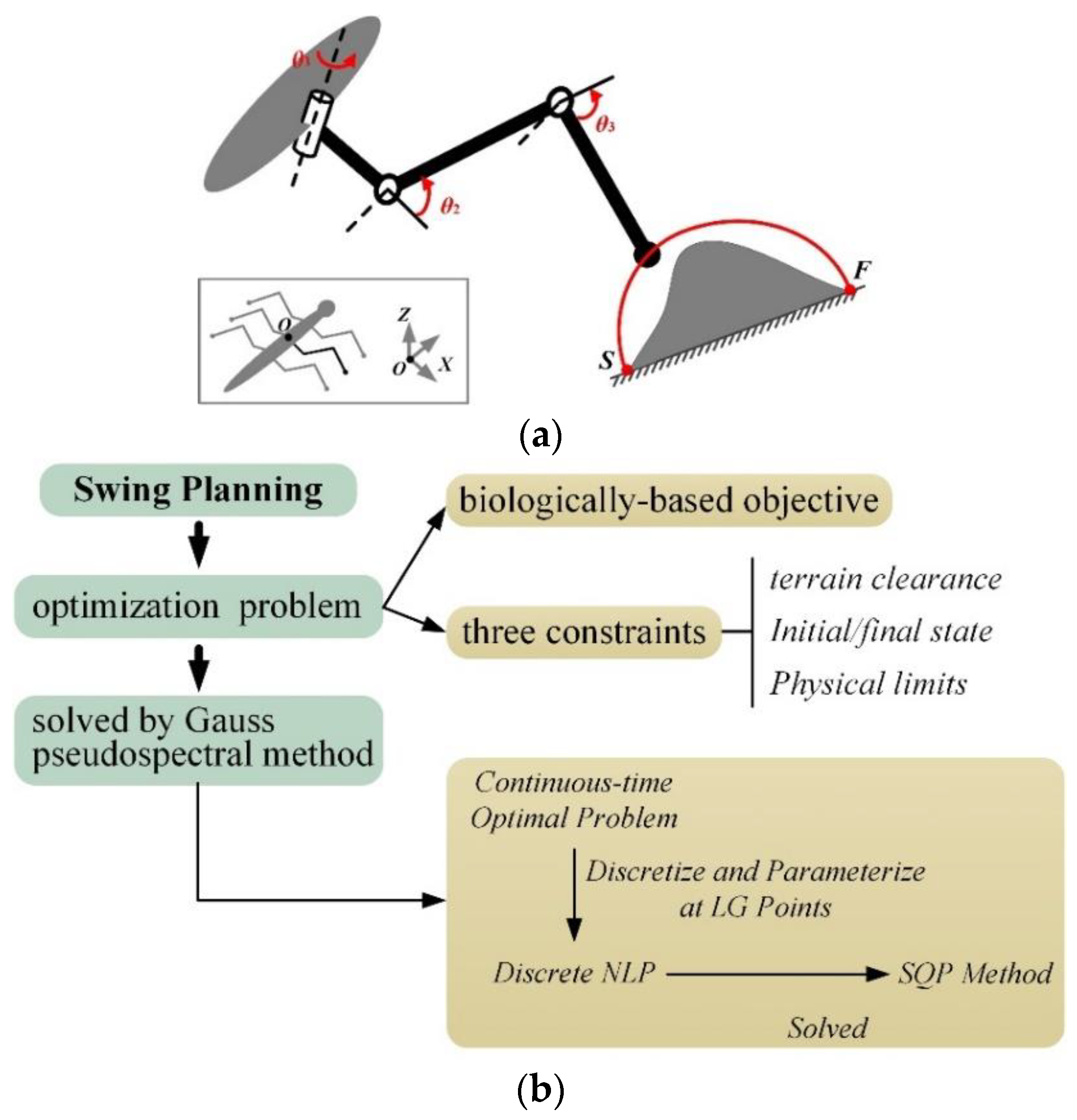
Figure 5.
Simulation platform of the six-legged robot, and consecutive snapshots of the robot walking over rugged terrain.
Figure 5.
Simulation platform of the six-legged robot, and consecutive snapshots of the robot walking over rugged terrain.
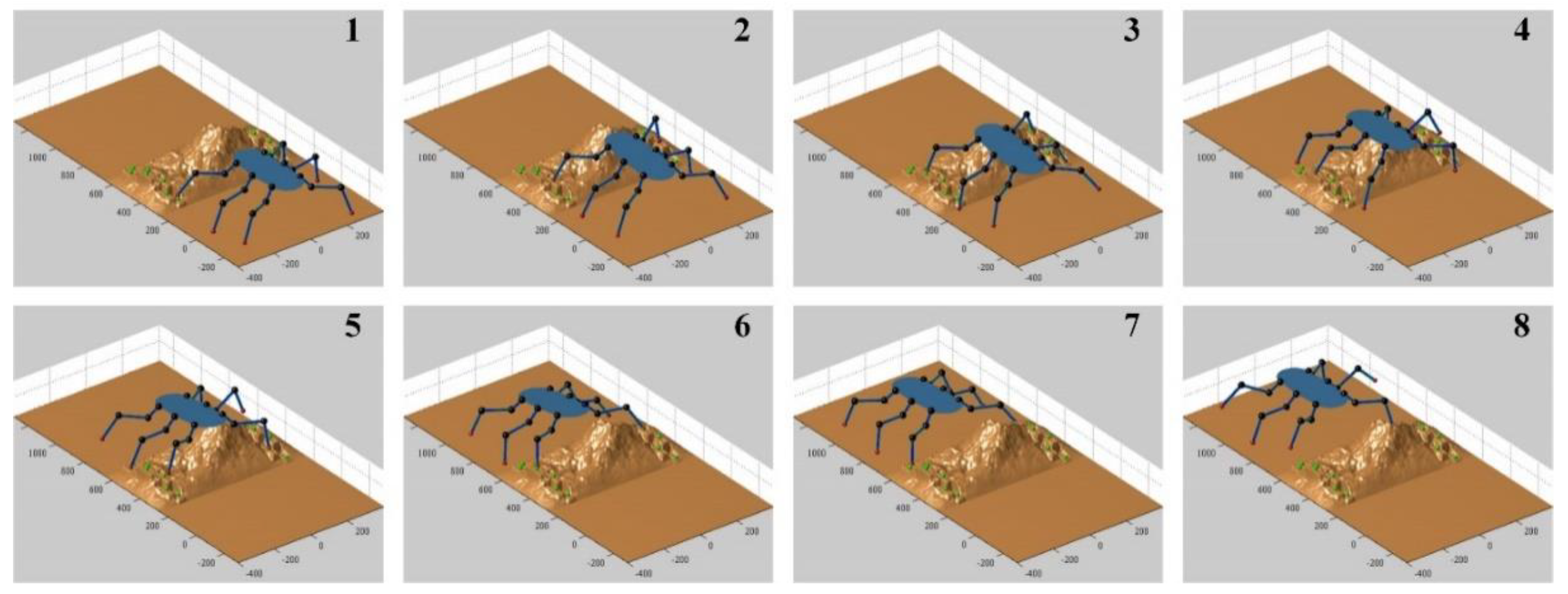
Figure 6.
Motion planning of the robot torso.

Figure 7.
Trajectories of all the joints of the robot.
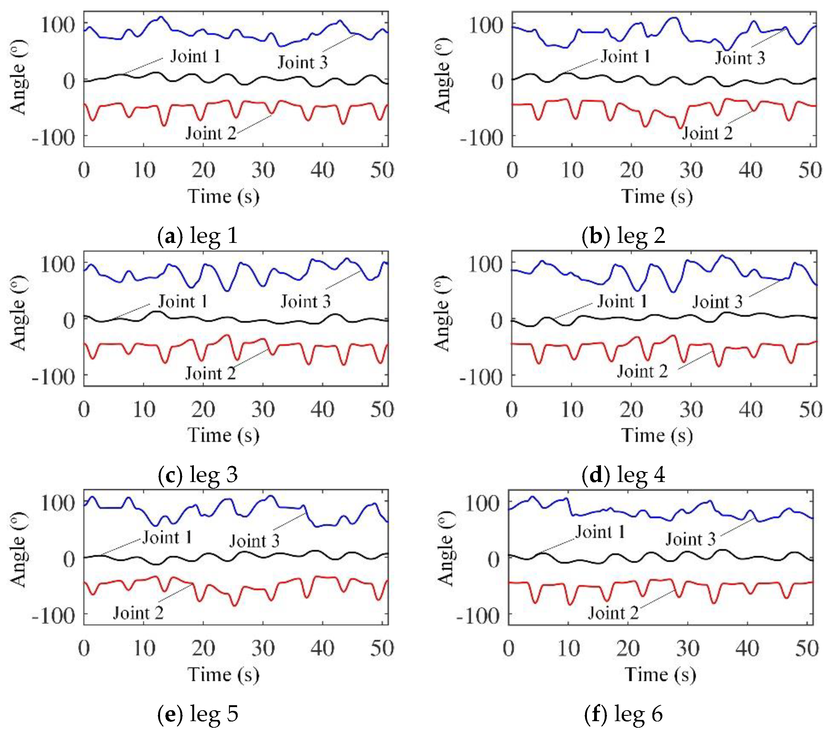
Figure 8.
Physical prototype of the robot.
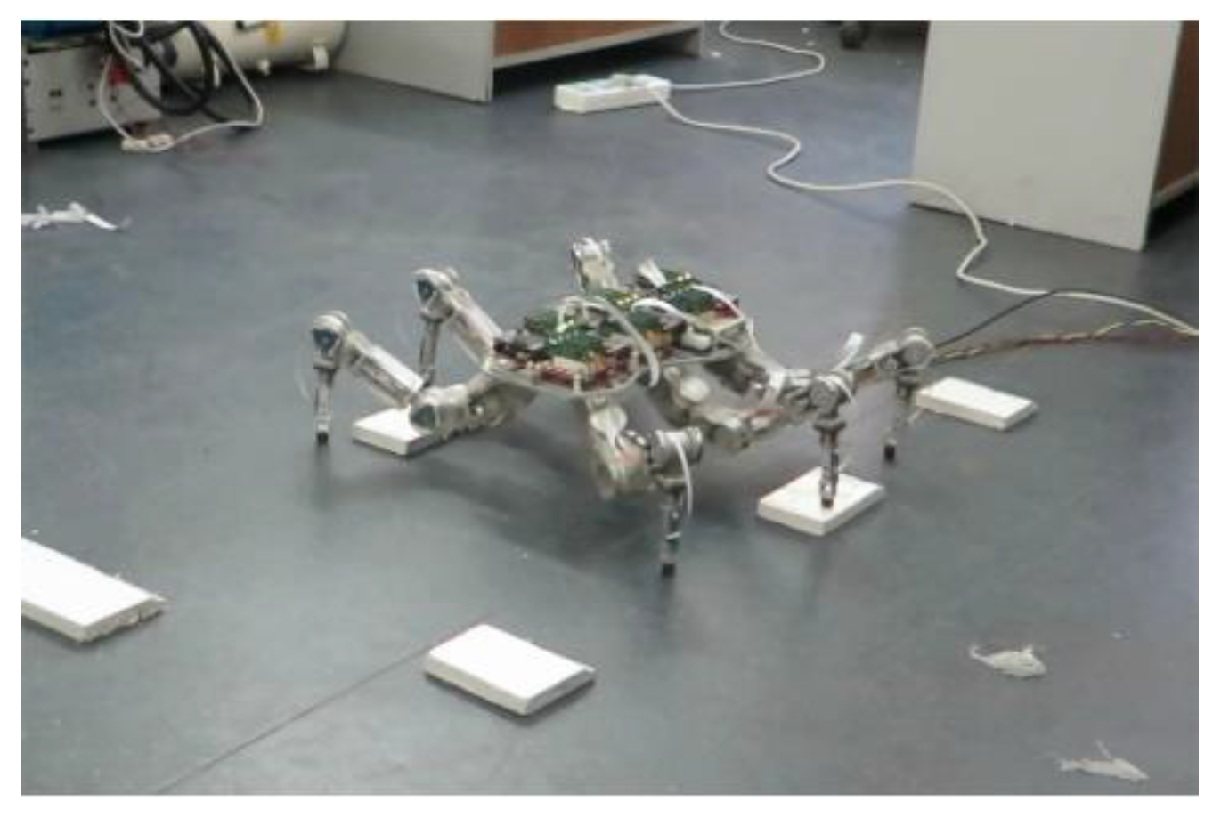
Figure 9.
Schematic of walking experiment on irregular wave terrain.
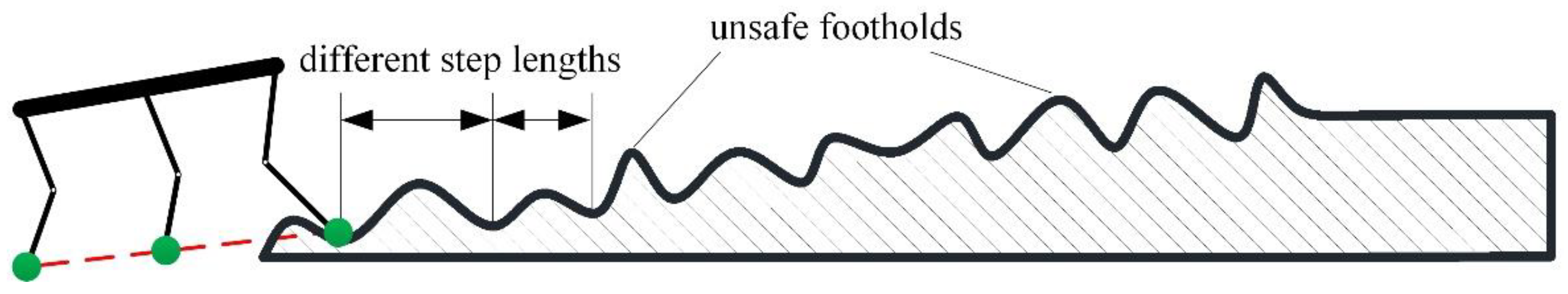
Figure 10.
Consecutive snapshots of the walking experiment on irregular wave terrain.
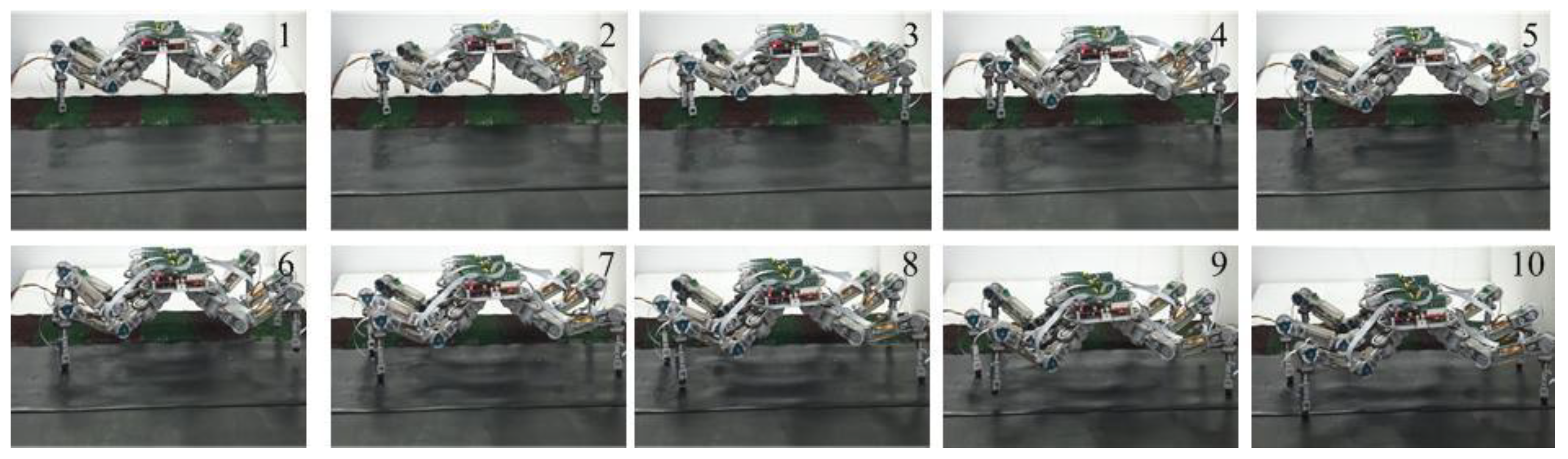
Figure 11.
Movement measurements during the walking on irregular wave terrain. (a) the torso pose. (b) joint trajectories of the left foreleg.
Figure 11.
Movement measurements during the walking on irregular wave terrain. (a) the torso pose. (b) joint trajectories of the left foreleg.
© 2019 by the authors. Licensee MDPI, Basel, Switzerland. This article is an open access article distributed under the terms and conditions of the Creative Commons Attribution (CC BY) license (http://creativecommons.org/licenses/by/4.0/).
Share and Cite
MDPI and ACS Style
Chen, J.; Gao, F.; Huang, C.; Zhao, J. Whole-Body Motion Planning for a Six-Legged Robot Walking on Rugged Terrain. Appl. Sci. 2019, 9, 5284. https://doi.org/10.3390/app9245284
AMA Style
Chen J, Gao F, Huang C, Zhao J. Whole-Body Motion Planning for a Six-Legged Robot Walking on Rugged Terrain. Applied Sciences. 2019; 9(24):5284. https://doi.org/10.3390/app9245284
Chicago/Turabian StyleChen, Jie, Fan Gao, Chao Huang, and Jie Zhao. 2019. "Whole-Body Motion Planning for a Six-Legged Robot Walking on Rugged Terrain" Applied Sciences 9, no. 24: 5284. https://doi.org/10.3390/app9245284
Note that from the first issue of 2016, this journal uses article numbers instead of page numbers. See further details here.