Article

Optimization of the Orifice Shape of Cooling Fan Units for High Flow Rate and Low-Level Noise in Outdoor Air Conditioning Units

1
LG Electronics, Changwon 2nd Factory, Seonsan-dong, Changwon-city, Keongsang Namdo 51554, Korea
2
School of Mechanical Engineering, Pusan National University, Busan 46241, Korea
*
Author to whom correspondence should be addressed.
Appl. Sci. 2019, 9(23), 5207; https://doi.org/10.3390/app9235207
Submission received: 6 November 2019 / Revised: 23 November 2019 / Accepted: 26 November 2019 / Published: 29 November 2019
(This article belongs to the Special Issue Recent Advances in Flow-Induced Noise)

Abstract

:
Demand for air conditioners is steadily increasing due to global warming and improved living standards. The noise, as well as the performance of air conditioners, are recognized as one of the crucial factors that determine the air conditioners’ values. The performance and noise of the air conditioner are mostly determined by those of its outdoor unit, which in turn depend on those of the cooling fan unit. Therefore, a cooling fan unit of high-performance and low noise is essential for air-conditioner manufacturers and developers. In this paper, the flow performance and flow noise of the entire outdoor unit with an axial cooling fan in a split-type air-conditioner were investigated. First, a virtual fan tester constructed by using about 18 million grids is developed for highly resolved flow simulation. The unsteady Reynolds-Averaged Navier–Stokes equations are numerically solved by using finite-volume computational fluid dynamics techniques. To verify the validity of the numerical analysis, the predicted P–Q curve of the cooling fan in a full outdoor unit is compared with the measured one. There was an excellent agreement between the two curves. The further detailed analysis identifies the coherent vortex structures between the fan blade tip and fan orifice, which adversely affect the flow performance and causes flow noise. Based on this analysis, the optimization of fan orifice was carried out using the response surface method with three geometric parameters: inlet radius, neck length, and outlet angel of the orifice. The optimum layout for the high flow rate is proposed under the understanding that the increased flow rate can be converted to noise reduction. The additional computation using the proposed optimum orifice shows that the flow rate is increased by 4.6% at the operating point. Finally, the engineering sample was manufactured by using the optimum design, and the measured data confirmed that the flow rate were increased by 2.1%, the noise reduction was made by 2.8 dBA, and the power consumption is reduced by 4.0% at the operating rotational speed.

1. Introduction

As environmental pollution becomes serious, there is a growing interest in a pleasant living environment. Accordingly, there is a steady increase in demand for home appliances that control indoor air. A typical example is an air conditioner. The air conditioner is used not only to cool the air by removing heat in the room but also to control the air quality by lowering the humidity. The air conditioner is used continuously regardless of the season so that the consumers are exposed directly to the air conditioner and are sensitive to its performance and noise. Therefore, related manufacturers and developers are continually investing in research to improve air conditioner performance and to reduce noise.
The noise of a split-type air conditioner is classified into the noise due to the outdoor unit and the indoor unit. Since the indoor unit is installed in the room, the consumer is directly subject to the noise of the indoor unit. However, the device generating noise is only the fan in the indoor unit, and thus the noise level of the indoor unit is relatively low. On the other hand, the outdoor unit has more equipment than the indoor unit, such as compressors, evaporators, and fans, which in turn cause more noise problems. The noise of outdoors often leads to a dispute between the neighbors so that noise-related regulations vary depending on the region. The overall performance of the split-type air conditioner is highly dependent on the performance of the outdoor unit, which in turn is closely related to the performance of the cooling fan in the outdoor unit. Therefore, to improve the performance of the air conditioner, a fan with a high flow rate is required. However, in general, the increase in fan airflow is directly related to the increase in noise. Therefore, it is essential for securing the market competitiveness of the manufacturer to develop high flow-performance and low-noise fans. In this study, the flow and noise performance in the outdoor unit of air-conditioner is investigated and improved by developing the high performance and low noise fan units.
Lee et al. [1] presented a hybrid computational aeroacoustics (H-CAA) method for efficiently predicting an internal aerodynamic noise of a centrifugal fan unit in a household refrigerator. Heo et al. [2] used the H-CAA method and developed low-noise centrifugal fans by introducing the inclined S-shaped trailing edge. These studies confirmed that the H-CAA method could be reliably used to predict the BPF noise of the fan unit. By extending these works, Heo et al. developed an efficient numerical method for predicting broadband noises as well as tonal noise of a centrifugal fan [3]. The proposed method is based on the Unsteady Fast Random Particle Mesh (U-FRPM) method. Utilizing these numerical methods, they [4] improved aerodynamic and aeroacoustics performance of an axial-flow fan unit by modifying its housing structure without changing the fan blade. Zhao et al. [5] investigated the shapes of the tip and trailing edge of axial fan blades to reduce fan noise in an outdoor unit. Jiang et al. [6] investigated the aeroacoustics of an axial fan in an outdoor unit. Fukano’s model, combined with typical computational fluid dynamics (CFD) simulation, is used to predict the broadband noise. After the predicted results were compared with the measured data, the distance to blade trailing edge is proposed as an essential parameter to improve the accuracy of noise predictions in the Fukano’s model. Wright et al. [7] presented the aerodynamic and acoustic properties of axial-flow fans with swept blades based on the theory of Kerschen and Envia for swept cascades. The experimental results confirmed that the swept-bladed fans show noise savings compared to the zero-sweep baseline model. Ye et al. [8] investigated the effects of various tip structures on the flow field, losses distribution, and noise characteristics and improved fan performance by changing the blade tip structure. It was shown that the grooved blade tips improved the efficiency by reducing mixing losses between the leakage flow and mainstream but increased the fan noise.
These studies [4,5,6,7,8] revealed that the characteristics of gap flow between the tip of the fan blade and the fan orifice (housing or shroud) are critical to the aerodynamic and aeroacoustic performance of fans. However, most of these studies concerned a fan unit alone or a fan in a simplified outdoor unit. The axial fan used in an outdoor unit has a complicated inflow structure, and even the same fan has different performance depending on the inflow structure affected by various devices. Notably, in the case of the outdoor unit, there are many components, not only an axial fan but an orifice, a heat exchanger, a heat sink, a motor, and a motor mount. These components can affect the flow performance as well as the noise of the outdoor unit. In this study, the whole outdoor unit, including these components, is investigated. As described above, among the components, the orifice is known to be one of the main parts affecting the flow and noise performances of an axial fan. As the cooling fan rotates in the outdoor unit, complicated tip vortex structures are created, which can adversely affect the flow performance and noise of fan [9,10,11]. The orifice organizes the flow by guiding the flow path between the orifice and the blade tip. In this study, the shape of an orifice is optimized to maximize the flow rate and thus to reduce the noise of an axial fan in the outdoor unit of an air conditioner.

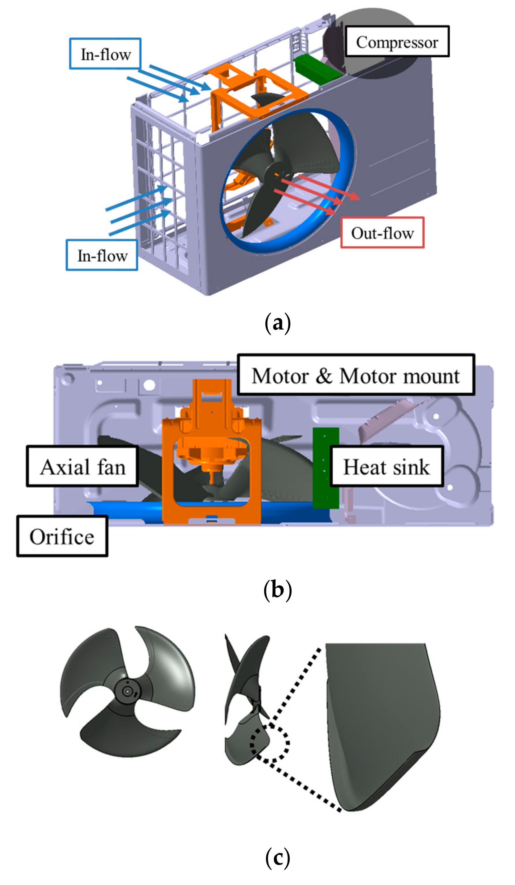
2. Targeted Axial-Flow Fan in Outdoor Units

Figure 1a shows the geometries of the internal structure of a targeted outdoor unit. The outdoor unit consists of an axial-flow fan, an orifice, a grille, a heat exchanger, a motor, and a motor-mount, as shown in Figure 1b. The axial-flow fan unit is used to drive airflow through the outdoor unit and to cool the heat exchanger. Figure 1c shows the axial-flow fan. The axial-flow fan consists of three blades. The diameter of the fan is 400 mm and has a rake shape similar to the winglet of airplane to reduce the tip-wake and flow noise. Note that all of devices except the heat exchanger are considered in the current study. The effects of heat exchanger are accounted for by considering additional pressure loss due to it.

3. Experimental Analysis of Targeted Outdoor Units

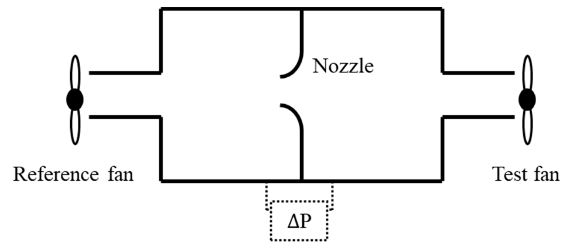
3.1. Experimental Set-Up for Characterizing Flow Performance

To characterize the flow performance of the targeted outdoor unit of air-conditioner, the fan performance experiment was conducted. The fan performance tester satisfying the regulations of AMCA (Air Movement and Control Association) 210-07 which provides methodology for testing the air moving devices is used. To improve the measurement accuracy, a large chamber of 1500(L) × 600(W) × 600(H) mm, five different-sized nozzles and two screens were installed in the fan performance tester. The pressure difference between the inlet and outlet of nozzle is measured, and the flow rate is calculated from the measured differential static pressure. This system is schematically shown in Figure 2. Consequently, the combination of measured static pressure and flow rate is arranged to determine the P–Q curve. The more detailed information about the fan performance tester was provided in the reference [4]. The measured P–Q curve is presented in the next section where the measured P–Q curve is compared with the predicted one to confirm the validity of numerical results.

3.2. Experimental Set-Up for Characterizing Noise Performance

In this study, to characterize the acoustic performance of the targeted outdoor unit, the spectral sound pressure levels were measured in the anechoic chamber. The experiment was conducted in accordance with the national test standard, KS (Korean Industrial Standards) C 9306 for air-conditioners [12]. The tested fan system is fixed at the center of the chamber and the microphone was installed downstream at a distance of 1 m from the center of an axial fan. The acoustic pressure was measured with a sampling frequency of 6400 Hz and a frequency resolution of 1 Hz. The measured overall sound pressure level with increasing rotating speed of fan is represented in Figure 3.

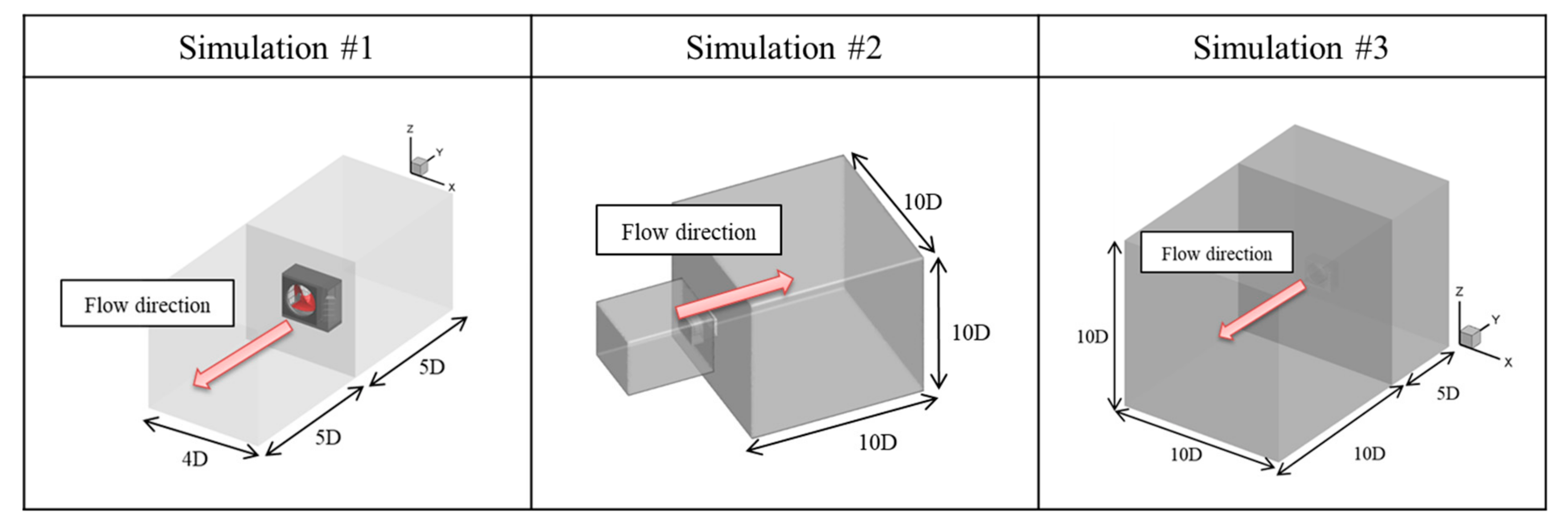
4. Numerical Methods and Validation

4.1. Governing Equations and Numerical Methods

To analyze the airflow driven by the axial-flow fan in the outdoor unit numerically, the following three-dimensional incompressible unsteady Reynolds-Averaged Navier–Stokes (RANS) equations are used as the governing equations:
x j ρ u j = 0 ,
t ( ρ u i ) + x j ( ρ u j u i ) = p x i + x j μ u i x j + u j x i ρ u j u i ¯
Equations (1) and (2) are numerically solved using a finite volume method based on the unstructured grids. The Re-Normalization Group (RNG) k-ε model is used as the turbulence model [13,14,15,16], and the standard wall function is used to model near-wall flows. For the numerical solutions of turbulent kinetic energy and turbulent dissipation rate, the first-order upwind discretization scheme is selected. Second-order upwind discretization scheme is used to solve the momentum term, the Semi-implicit Method for Pressure-Linked Equations (SIMPLE) scheme is used to solve the pressure-velocity coupling equations. The first order implicit method is selected for the transient discretization. The time step is 0.01/angular velocity. The under-relaxation factors are set to be 0.3, 0.7, 0.8, and 0.8 for pressure, momentum, turbulent kinetic energy, and turbulent viscosity, respectively. The volume flow rate at the discharge zone is used as the convergence criteria. The sliding mesh technique is used to simulate the rotating of the axial fan. These numerical methods are realized using the commercial CFD solver of ANSYS fluent.
Ffocws-Williams and Hawkings (FW–H) equation [17] in the following form is used for the prediction of radiated acoustic pressure:
4 π c 2 H ρ x , t = t S ρ 0 v n r 1 M r d S η x i S p i j n j r 1 M r d S η + 2 x i x j V T i j r 1 M r d 3 η .
Note that the volume source, the last term in the right-hand side of Equation (3), which is known to be negligible at low Mach number flow, is neglected.

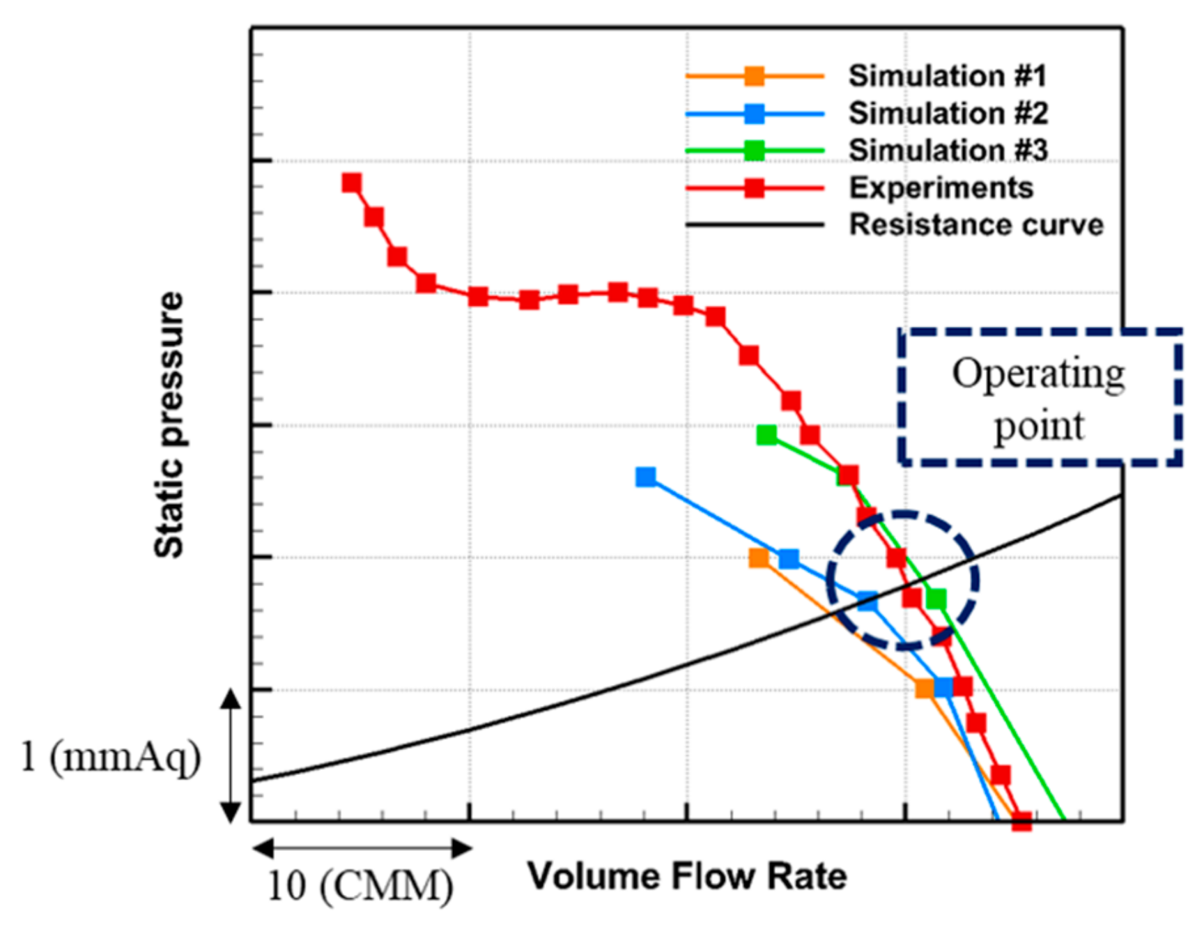
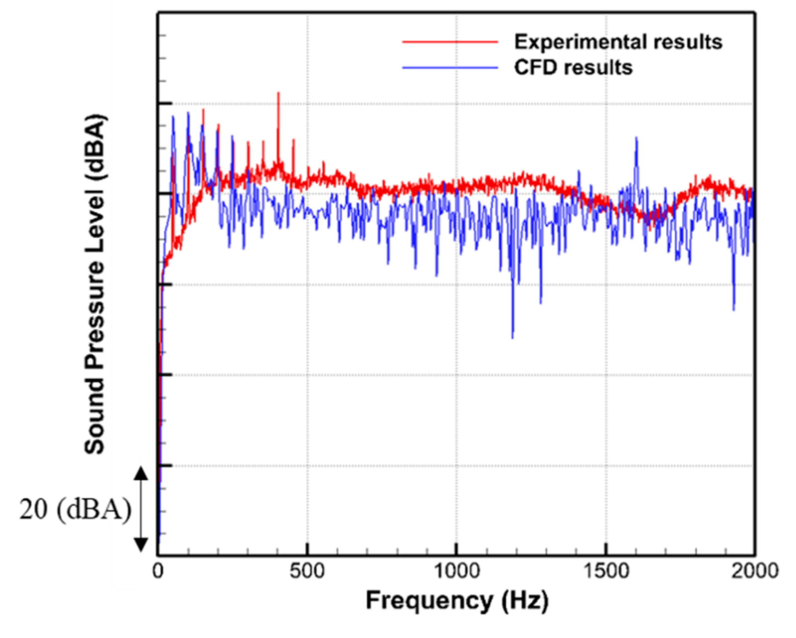
4.2. Validation of Numerical Model

To investigate the detailed characteristics of the flow field driven by the axial fan in the outdoor unit more accurately, the virtual fan-performance tester (VFT) is designed. To determine the dimensions of the virtual fan tester and the number of grids for the given outdoor unit, a grid-refinement study was carried out. Figure 4 shows the three types of VFTs made on a basis of D, which is the diameter of the fan. The static pressure on the inflow and outflow planes which are located upstream and downstream, respectively, of the axial-flow fan in the outdoor unit is specified as the inflow and outflow boundary conditions. To reproduce the experimental conditions of the actual fan-performance tester and to predict the P–Q curve of the outdoor unit, the pressure difference between inlet and outlet boundaries is varied. The wall boundary conditions are applied on the four side-planes parallel to the fan rotation axis and on the middle plane separating the upstream and downstream flows. The rotation speed is set to be 1000 RPM.
The numerical results predicted using the VFTs are compared with the measured one using the actual fan performance tester of which the specifications are described in Section 3.1. The validity of VFT is confirmed by comparing the numerical results with the experimental results. Figure 5 compares the P–Q curves predicted by using the VFTs with the measured data. The agreement is generally good between the predicted and measured results in the lower pressure region, but the discrepancy increases as the pressure increases. The difference seems to depend on the size of the virtual fan tester: as the size of the virtual fan tester increases, the agreement between the numerical and experimental results becomes closer. The final dimensions of the VFT and the number of grids are determined using these results, which show that Simulation #3 presents the reasonable agreement up to the operation point. The maximum relative error in the volume flow rate at the fixed static pressure is 4.0%. These results confirm the validity of the current numerical method. Note that the subsequent detailed flow analysis and the optimization were carried out for the operating point where the P–Q curve and the resistance curve, which is mainly due to the heat changer, meet together.
Aerodynamic noise due to fan-driven flow in the out-door unit is also predicted using the FW–H integral equation in Equation (3). The half-spherical shape of the FW–H integral surface was formed in the downstream direction. Figure 6 compares the predicted sound pressure spectrum with the measured one. There are good agreements at the blade-passing-frequencies between two results, though some differences are noticed in the broadband noise. The difference in the broadband high-frequency range is due to the intrinsic limitation of RANS equations in resolving the random components because the RANS equations are derived by averaging the Navier–Stokes equations. However, the difference between the numerical and experimental results is 2.1 dBA in terms of the overall sound pressure level because the tonal components dominantly contribute to the overall sound pressure level.

5. Numerical Results of Axial Fan System of Outdoor Unit

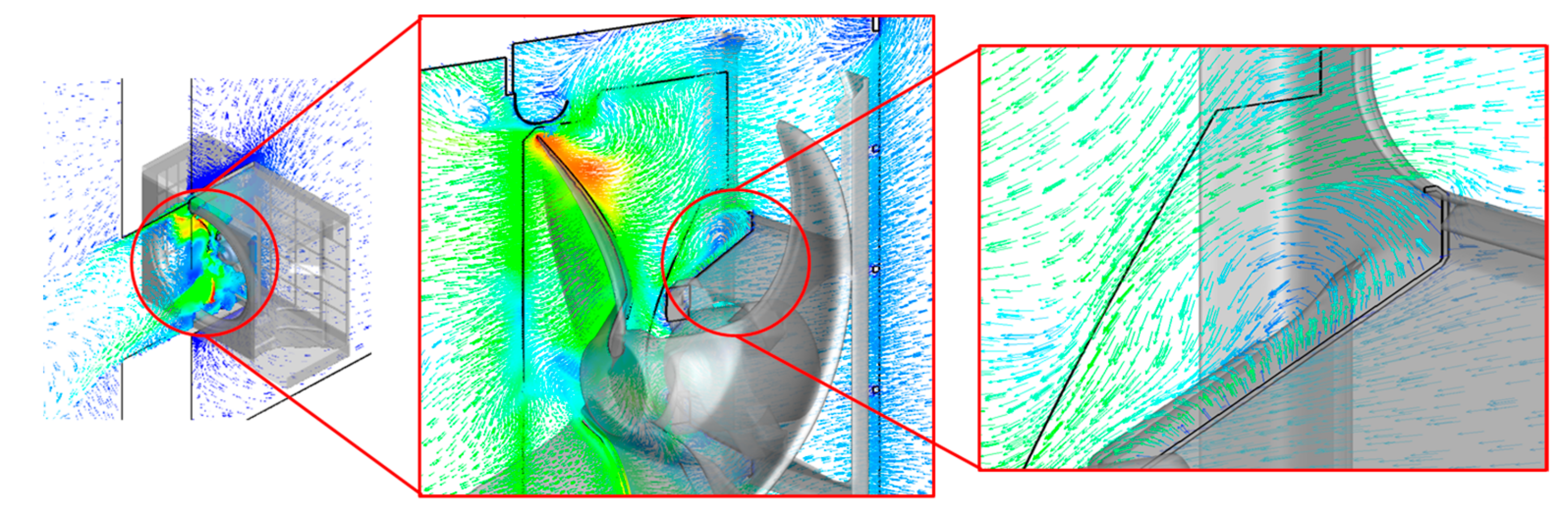
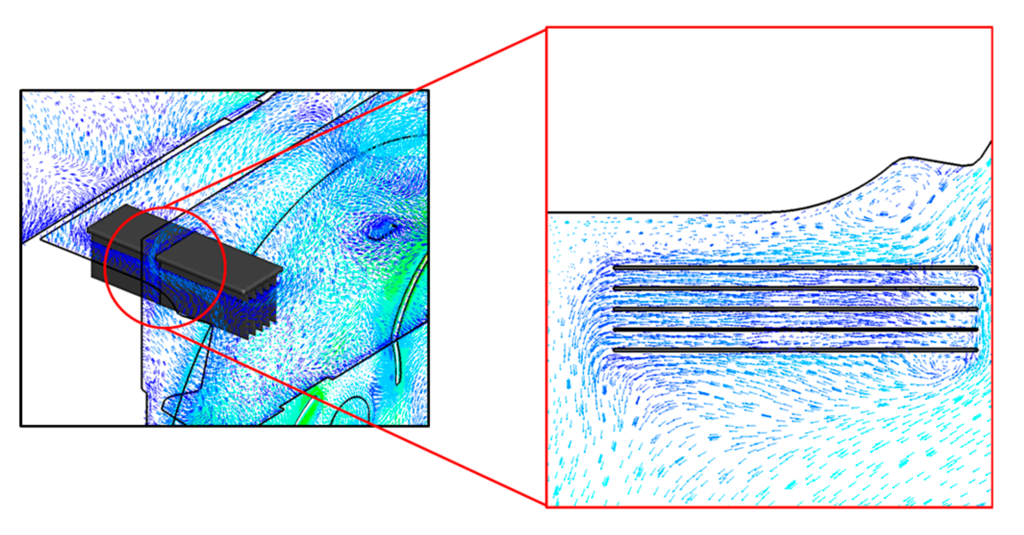
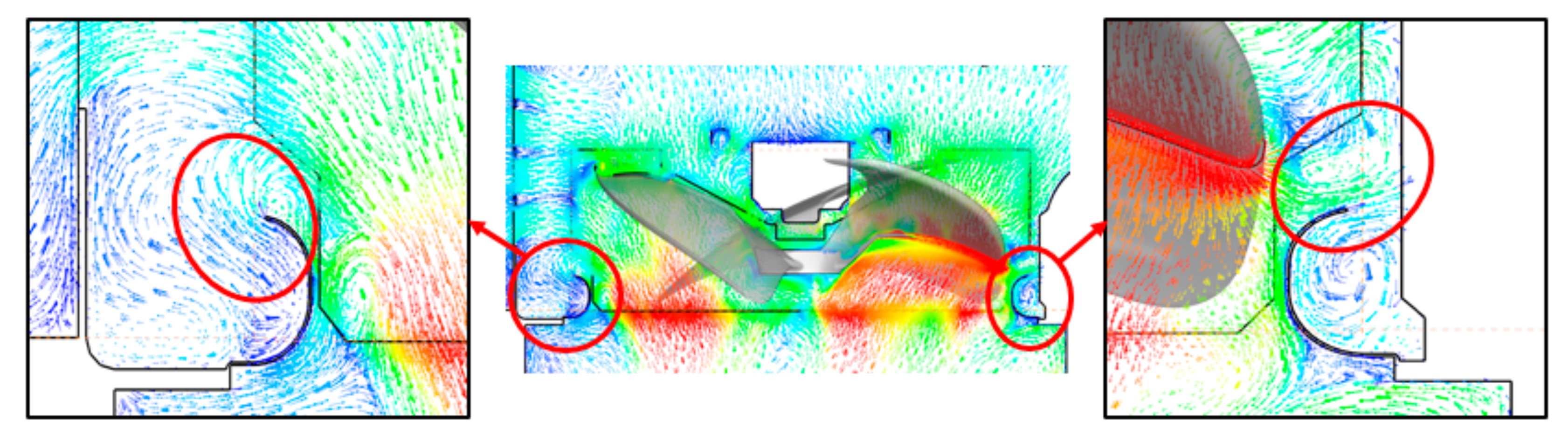
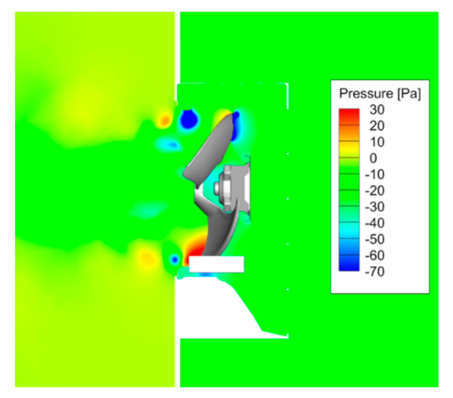
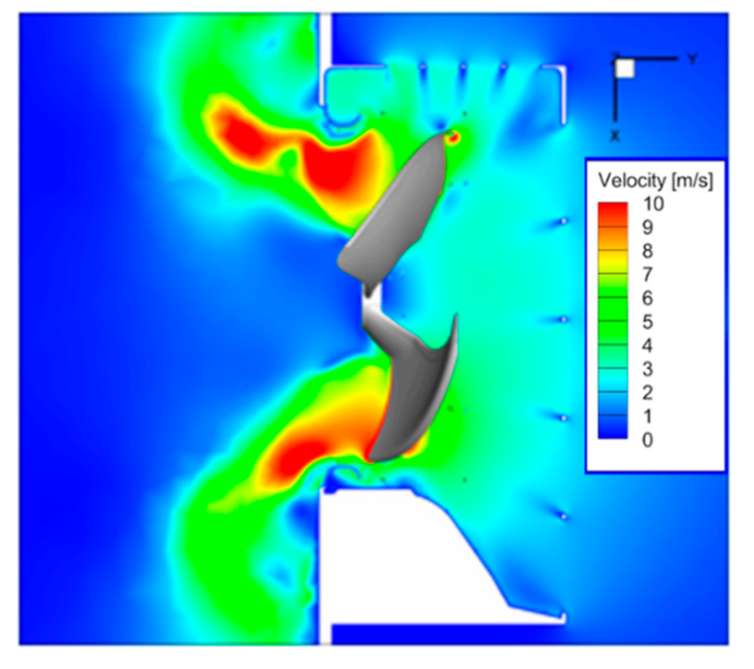
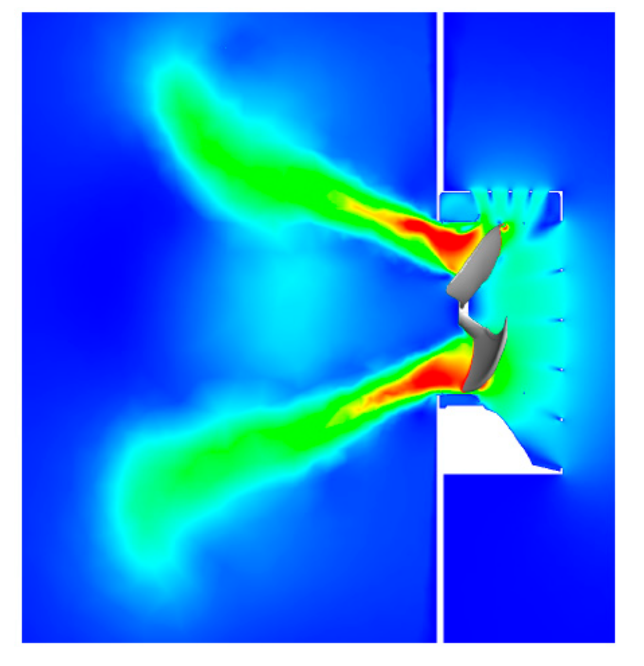
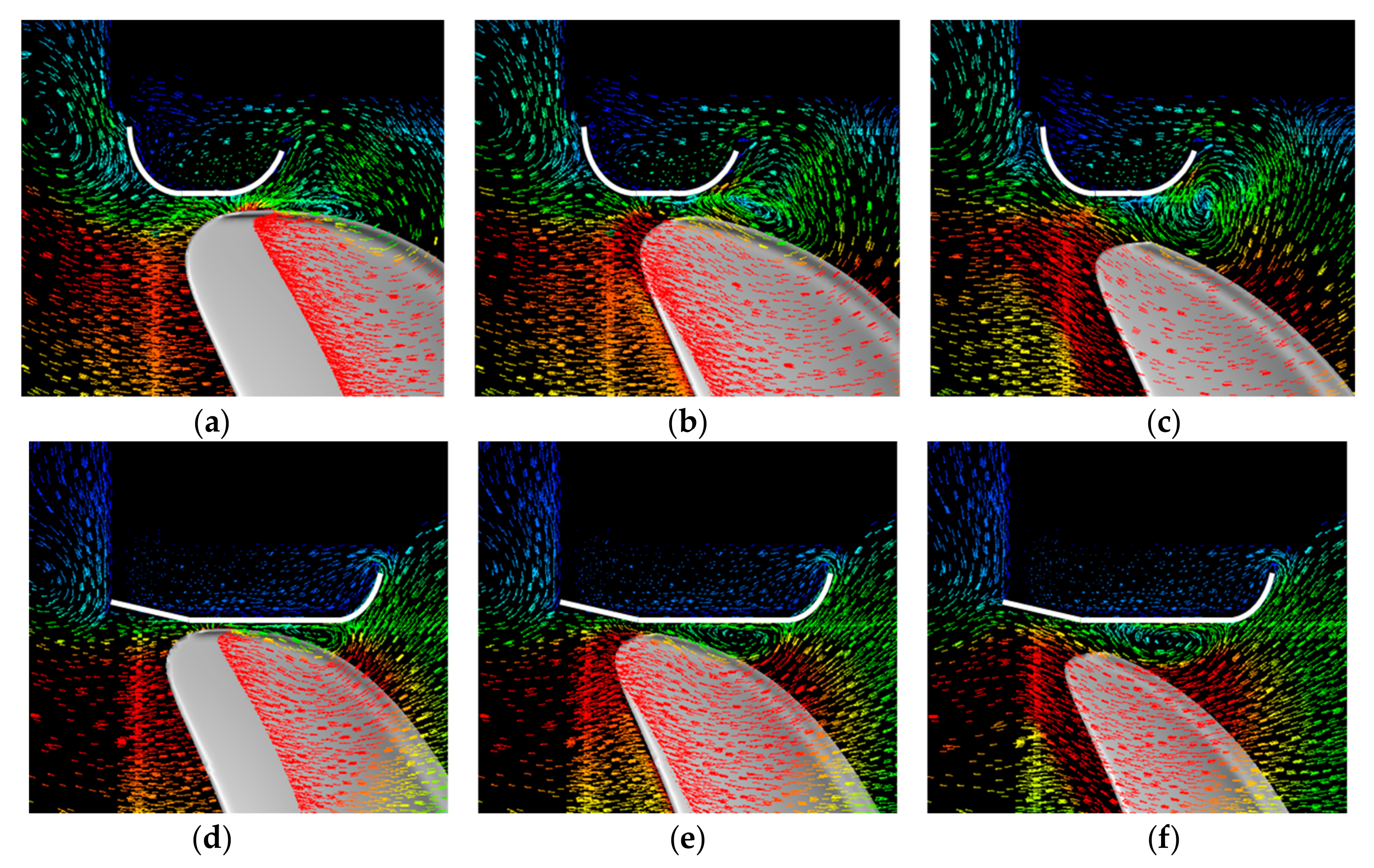
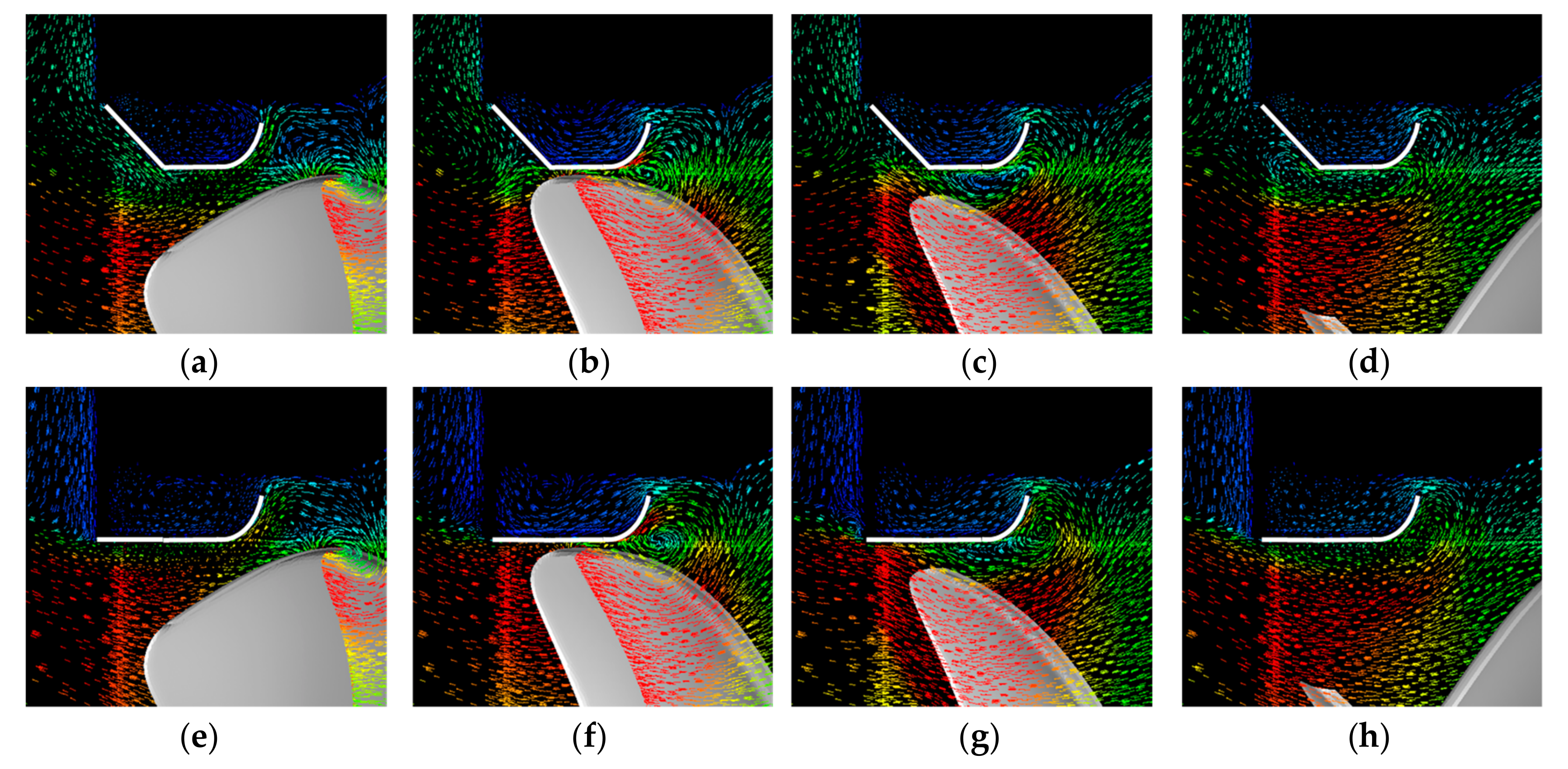
5.1. Analysis of Flow Field Driven by Axial Fan Systems of Outdoor Units

The flow field predicted for the targeted cooling fan system by using the VFT is investigated in detail. Since the computation domain includes the entire fluid region of the outdoor unit, the predicted flow field includes most of the essential characteristics of flow which involve the interaction of the driven flow with internal structures such as the motor-mount, the inlet-grille, the heat sink, and the orifice. Figure 7 shows the overall fluid velocity field on the vertical cross-sectional plane passing through the rotating center of the fan with the zoomed plot around the motor mount. It can be seen that the vortex flow is formed around the motor mount. However, this vortex flow is relatively weak in comparison to the vortex flow around the orifice.
Figure 8 shows the vector fields of fluid velocities on the vertical and horizontal cross-sectional planes passing through the heat sink with the zoomed plot around the heat sink. It can be seen that the fluid flow passes smoothly through the heat sink, which means the effective cooling of the heat sink through the airflow driven by the fan.
Figure 9 shows the vector field of flow velocities on the horizontal cross-sectional plane passing the rotating center of the fan with zoomed plots around the orifice. It can be seen that the strongest vortex structures are generated near the orifice than other components. It is well known that the tip vortex of the fan blade affects the flow performance and flow noise of the fan most significantly. The orifice is generally used to suppress this tip vortex and thus to increase the flow performance and to decrease the flow noise. These identified vortex flows can reduce the flow performance and increase flow noise of the axial flow fan, which implies that the orifice shape needs to be re-designed in combination with the tip shape of the axial-flow fans.
Figure 10 shows the iso-contours of the static pressure on the same horizontal cross-sectional plane. The circular contours with lower pressure value at its center are identified around the orifice, which indicates the core of vortex generated by the interaction of the blade tip with the orifice.
Figure 11 shows the iso-contours of the magnitudes of the flow velocity vectors on the same horizontal cross-sectional plane. The lower values are identified around the orifice, which means the vortex adversely affects the flow performance of the fan.

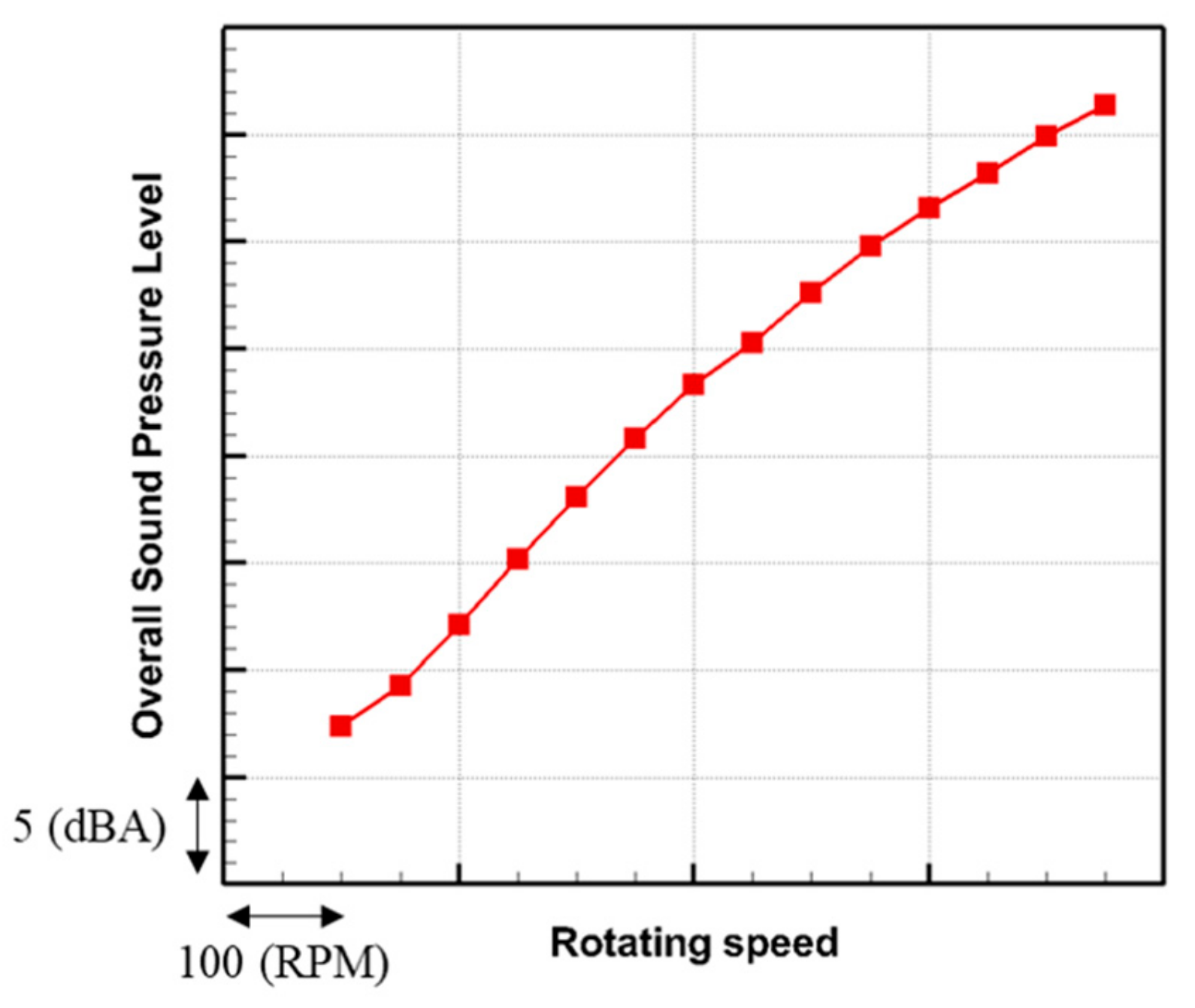
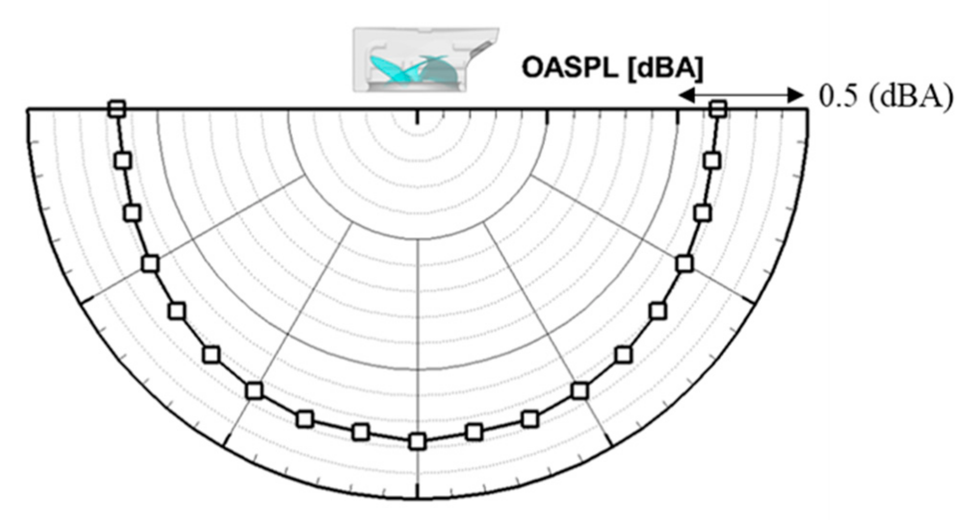
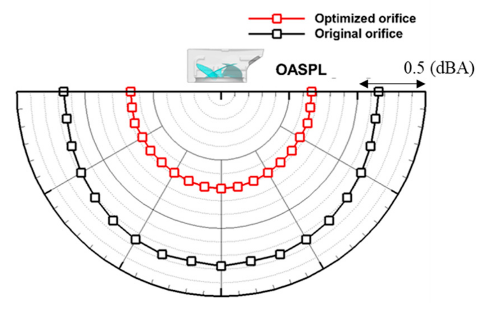
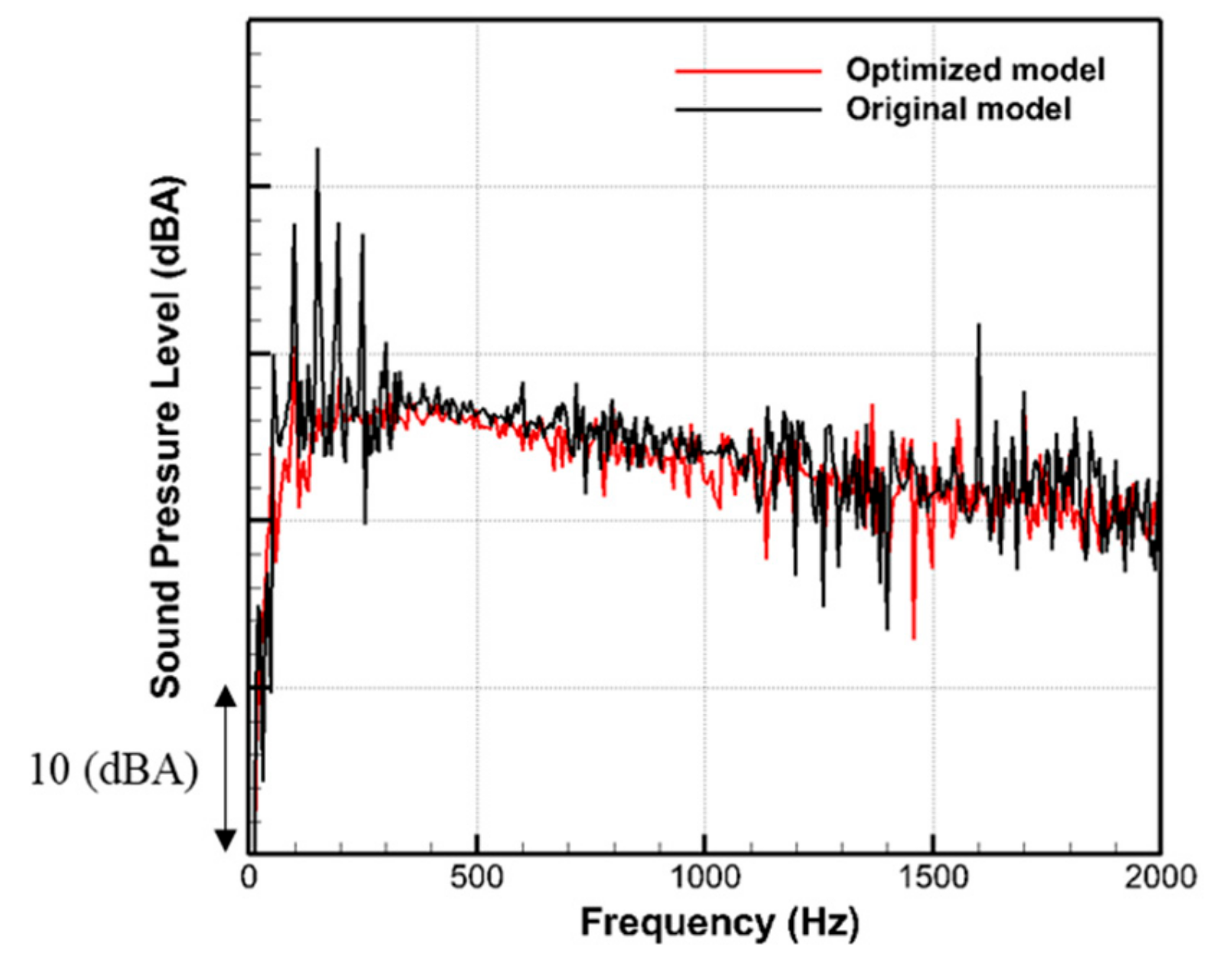
5.2. Analysis of Aeroacoustic Performance of the Fan System of Outdoor Units

Figure 12 shows the directivity of the overall sound pressure level of outdoor unit. It can be seen that the highest sound pressure wave propagates in the direct downstream direction normal to the fan rotational plane. This is well-known dipolar characteristics of fan noise.
Based on these flow and noise analysis results, a further investigation is carried out to find the optimum orifice shape, which can minimize the vortex observed between the orifice and the fan blades and thus improve the flow and noise performances.

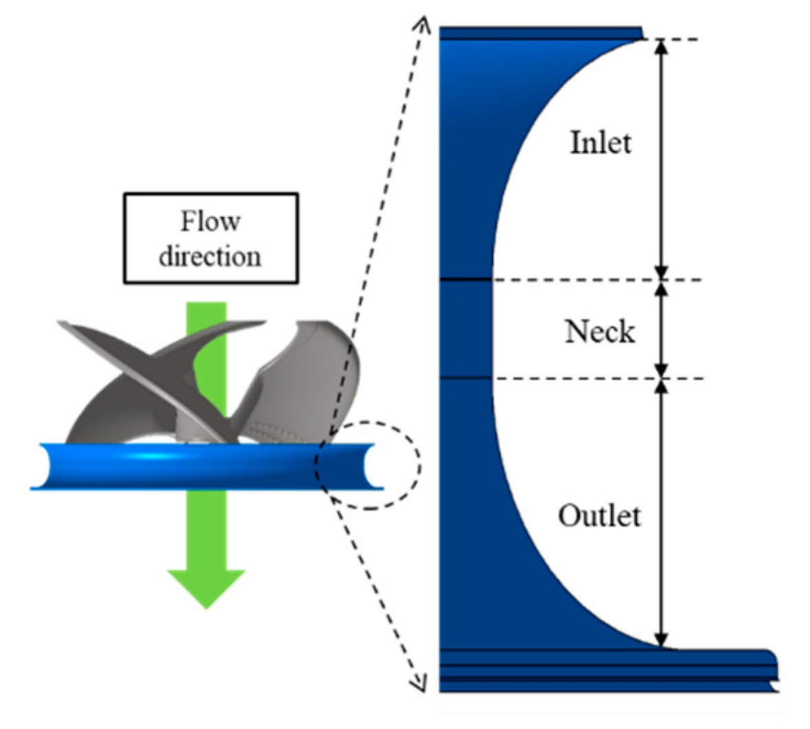
6. Optimization of Orifice Shape

6.1. Optimization Method

The orifice shape in the axial fan system of the outdoor unit is optimized for the maximum flow coefficient and the minimum sound pressure levels. The volume flow rate of the fan is generally proportional to the rotational speed of the fan, and the acoustic power of the fan is proportional to the 5th to 6th power of fan rotational speed. This dimensional analysis suggests that the optimization for the higher flow rate is more practical. The increase of volume flow rate through the optimization can be converted to the reduction of noise. To maintain the cooling capability of the fan, the volume flow rate must be equal to or higher than that of the original model. Therefore, if the volume flow rate is increased, the rotational speed of the fan can be reduced to adjust the volume flow rate to the original one. The noise of the outdoor system can be reduced due to the reduction of rotational speed.
The optimization is performed using the response surface method (RSM), which is a collection of mathematical and statistical techniques for empirical model building, can solve multiple responses over the entire area of interest, and produce more accurate solutions than other methods [18,19,20]. In this study, the optimization is performed using the following second-order regression equation:
η = β 0 + i = 1 k β i x i + i j k β i j x i x j ,
where η , β ,   and   x means a dependent variable, regression constants, independent variables, respectively. If the regression constants are determined using the numerical results, optimization can be derived by determining the dependent variables to get the maximum value of the independent variable from Equation (4).

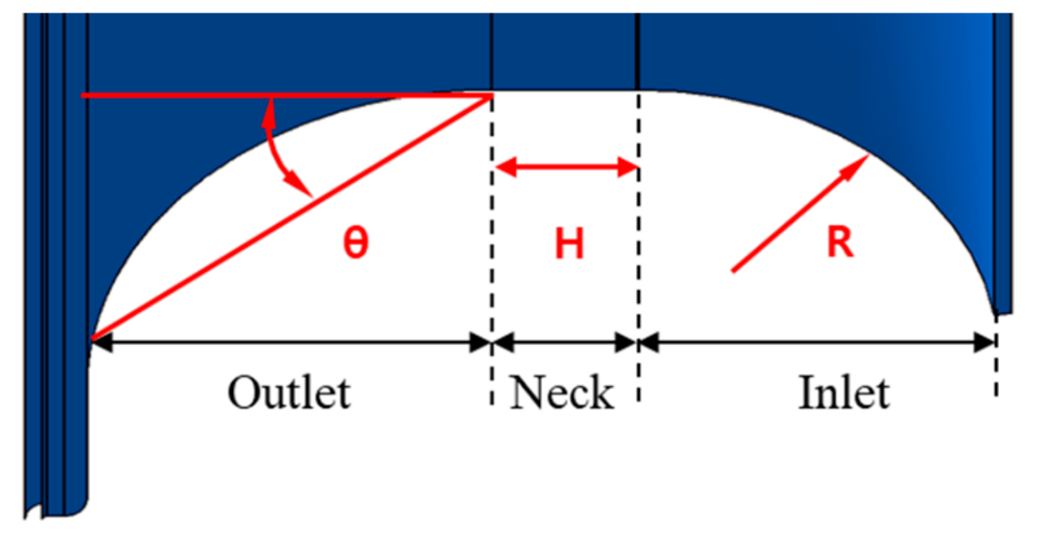
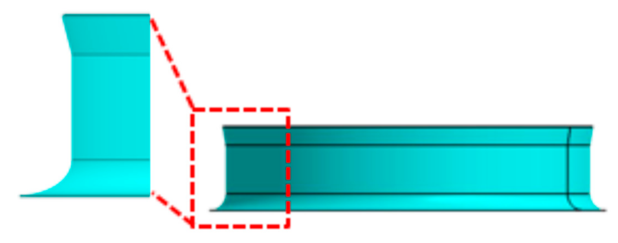
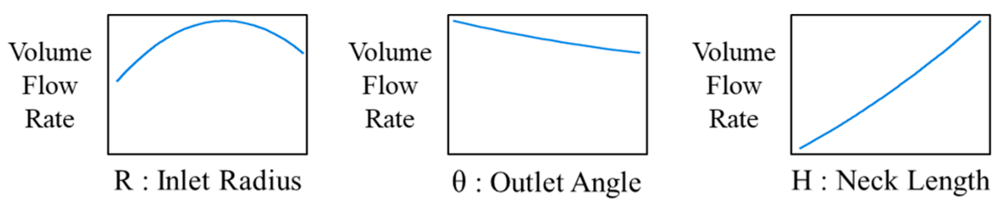
6.2. Geometric Parameters for Optimization of Orifice Shape

The orifice shape of this study can be divided into three sections depending on its role, as shown in Figure 13: inlet, neck, and outlet. First, in the inlet section, it is necessary to design a shape that can reduce the flow separation of the suction flow and prevent the reverse flow generated by the blade tip of the axial fan. The second is the neck section, which is the shape of a straight line. In this section, if the flow doesn’t develop sufficiently, it becomes the main cause of the flow noise and the loss of flow rates. Third, it is an outlet section that determines the directions of discharge flow and recovers the static pressure loss at the inlet section by serving as a diffuser. The straight shape of the outlet is advantageous for discharging performance. Figure 14 depicts the definitions of three design factors selected for the optimization of the orifice. The selected parameters (R, H, θ ) represents the shape of the inlet, neck, and outlet, respectively. Note that, although the original orifice shape includes the curved shape in the downstream field, a linear shape is chosen. The volume flow rate is chosen as an objective function. The ranges of three factors are determined to satisfy its geometric installation constraint. The levels of the factors are summarized in Table 1.

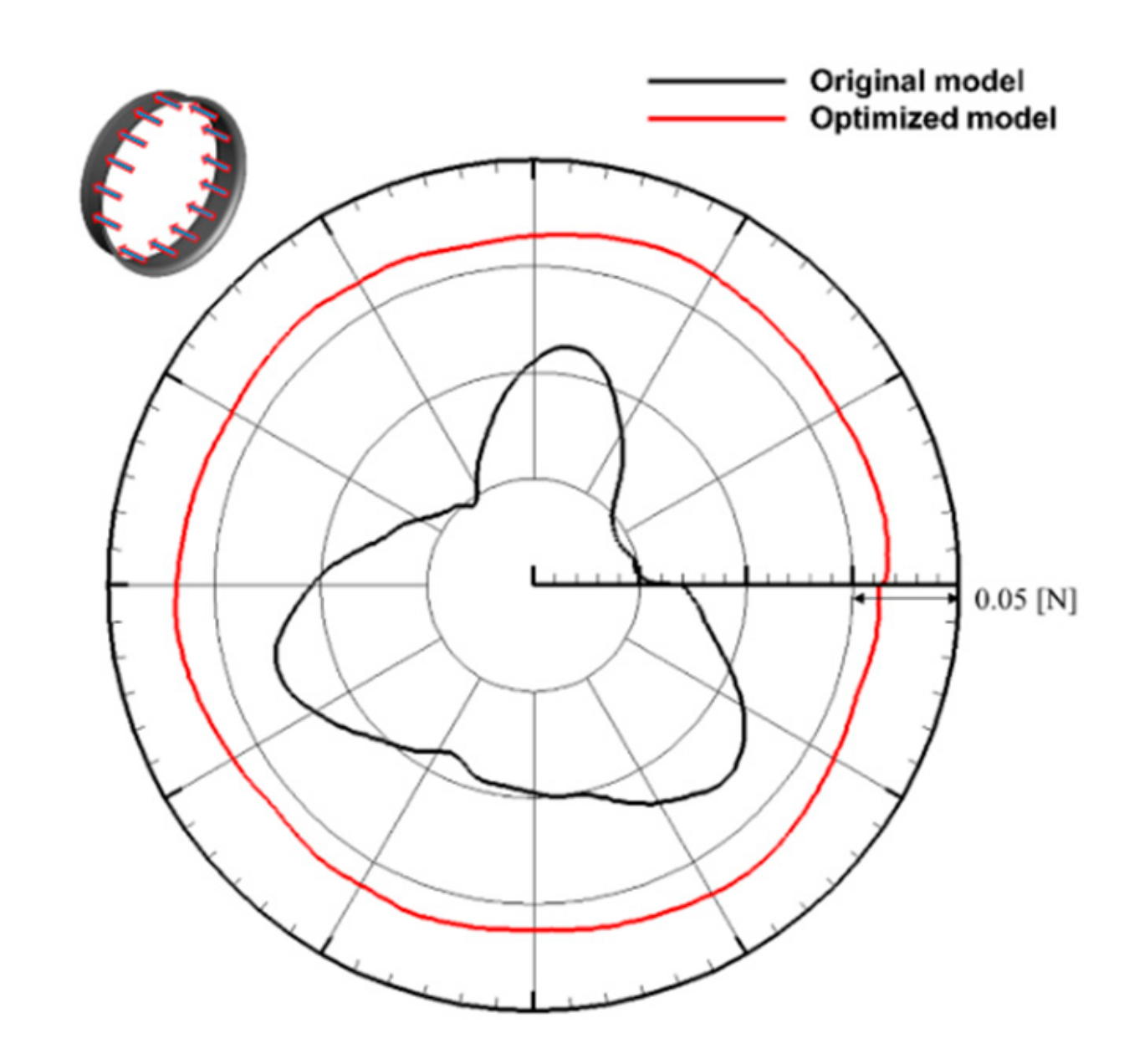
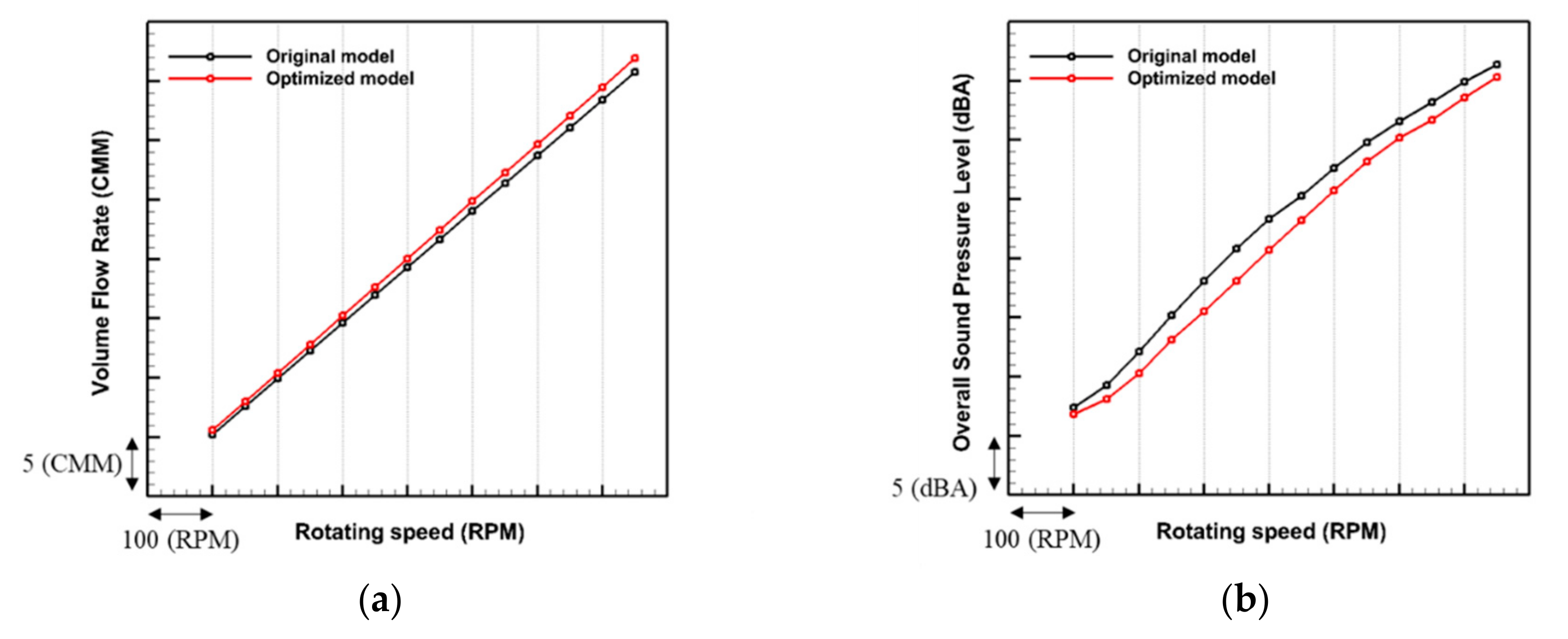
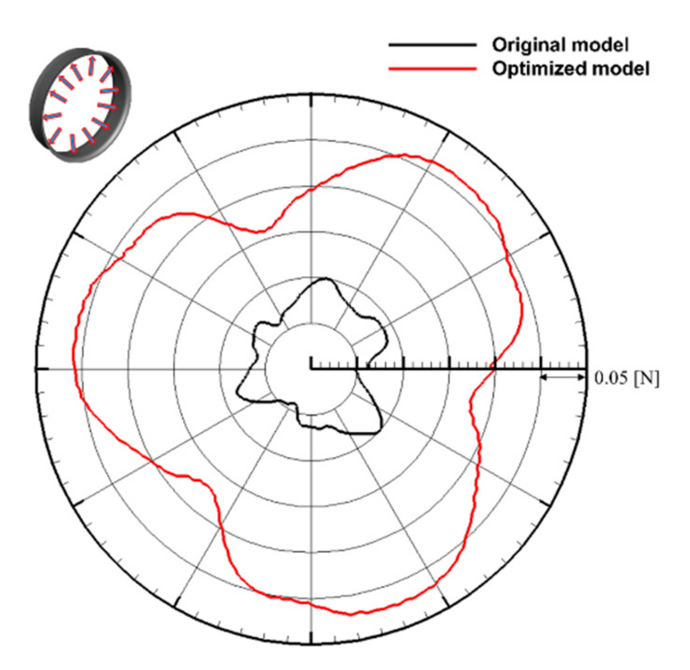
6.3. Optimization Results

The numerical optimization based on RSM is carried out for the maximum volume flow rate using 15 cases. The same numerical methods as used for the flow and noise predictions of the existing fan system described in the previous sections are applied to each of these cases. Based on these results, the quadratic function of Equation (4) is obtained from the RSM using the Minitab software (version 17.0, Minitab Inc., United States of America,). From the quadratic function, the influence of the three parameters on the volume flow rate is obtained, as shown in Figure 15. Among the three parameters, R [mm] representing the inlet shape showed a tendency to include the maximum value of the volume flow rate within the selected design range. However, the distribution of H [mm] representing the neck shape and θ [deg] representing the outlet shape has the maximum volume flow rate at the boundary of the set region. These results show that, as the length of the neck section is longer, and the discharge area of the outlet section is smaller, the flow rate is more increased. Note that the lower and upper limit of H and θ , respectively, is determined considering the allowable limit of orifice installation in the outdoor unit.
Figure 16 shows the optimum shape of orifice, and the optimal design values for each section are (R, H, θ ) = (19.2, 55, 10). The numerical simulation of flow field driven by the axial-flow fan combined with the optimized orifice in the outdoor unit is carried out, and the flow rate of the optimized orifice is found to be higher than the original orifice by about 4.6%. The detailed flow field obtained from the numerical simulation using the optimized orifice is shown in Figure 17 and Figure 18. Figure 17 shows the iso-contours of flow velocity magnitude on the horizontal cross-sectional plane. It can be found that the outlet flow direction of the outdoor unit using the optimized orifice is directed more downstream than that of the original one shown in Figure 8. It is emphasized that this dramatic change of flow pattern is achieved only by changing the orifice shape without changing the fan blade.
Figure 18 compares the flow velocity vectors around the orifice between the original and the optimized ones. It can be seen that the vortex structure generated at the inlet section of the original orifice almost disappears in the optimized orifice and the discharging flow is developed more sufficiently at the neck section of the optimized orifice than the original one. In addition, in case of original orifice shape, the tip vortex formed and separated from the blade tip interacts with the inlet of orifice, whereas the tip vortex in the optimized orifice system was developed in the neck section.
As shown in Figure 17, there is a significant change in the outlet flow pattern between the optimized and original models. To find the reason for the difference, Figure 19 compares the flow velocity vectors between different outlet angles ( θ ) at the fixed other design factors. Although the other two parameters are the same for each other, the tip vortex pattern changes significantly according to the variation of the outlet angle. In the case of the orifice with larger outlet angle, the tip vortex formed from the blade tip is convected downstream and interacts with the orifice vortex. The tip vortex in the case of the orifice with smaller outlet angle remains in the vicinity of the inlet of orifice and decay gradually. This result implies that the change in the outlet flow pattern is induced by the combination of the optimum design parameters but not just by the linear shape of the outlet part.
For more quantitative analysis of orifice roles, the radial and axial loadings of orifice surface were calculated, and its instantaneous distributions are shown in Figure 20 and Figure 21, respectively. It can be seen in Figure 20 that the three distinct lobs that are related to the three fan blades’ location are formed in the distribution of radial-direction loading of the optimized orifice, and its magnitude is higher than that of the original orifice. This implies that the optimized orifice guides the flow more effectively by pushing the airflow more in the centripetal direction. Contrary to the radial loading, as shown in Figure 21, the axial-direction loading of the optimized orifice shows circular shape, whereas that of the original orifice shows three lobs. The reason for this difference can be explained by using the difference in the tip vortex distributions between two orifices shown in Figure 18. The tip vortex in the optimized orifice interacts mainly with the neck part of the orifice, whereas the tip vortex in the original orifice interacts with the inlet part. Therefore, the tip vortex interacting with the neck part more affects the radial loading of the optimized orifice while the vortex interacting with the inlet part more affects the axial loading of the original orifice. However, the magnitude of axial loading is higher in the optimized orifice, which means that the optimized orifice makes more contribution to the airflow rate by pushing the air more in the axial direction.
Finally, the sound pressure radiation from the fan-driven flow in the outdoor unit is computed and compared between the original and optimized orifices. Figure 22 shows the predicted sound pressure spectrum. Although the optimization is carried out for the maximum volume flow rate, it can be seen that the spectral sound pressure levels from the outdoor unit with the optimized orifice was less than those of the original orifice. The reason for this seems to be due to the change of vortex strength of which the reduction can increase the flow rate and at the same time reduce aerodynamic noise. Figure 23 shows the directivity of SPLs predicted for the original and optimized orifices. It can be seen that the overall SPLs of the outdoor unit with the optimized orifice are reduced in all of the downstream directions.

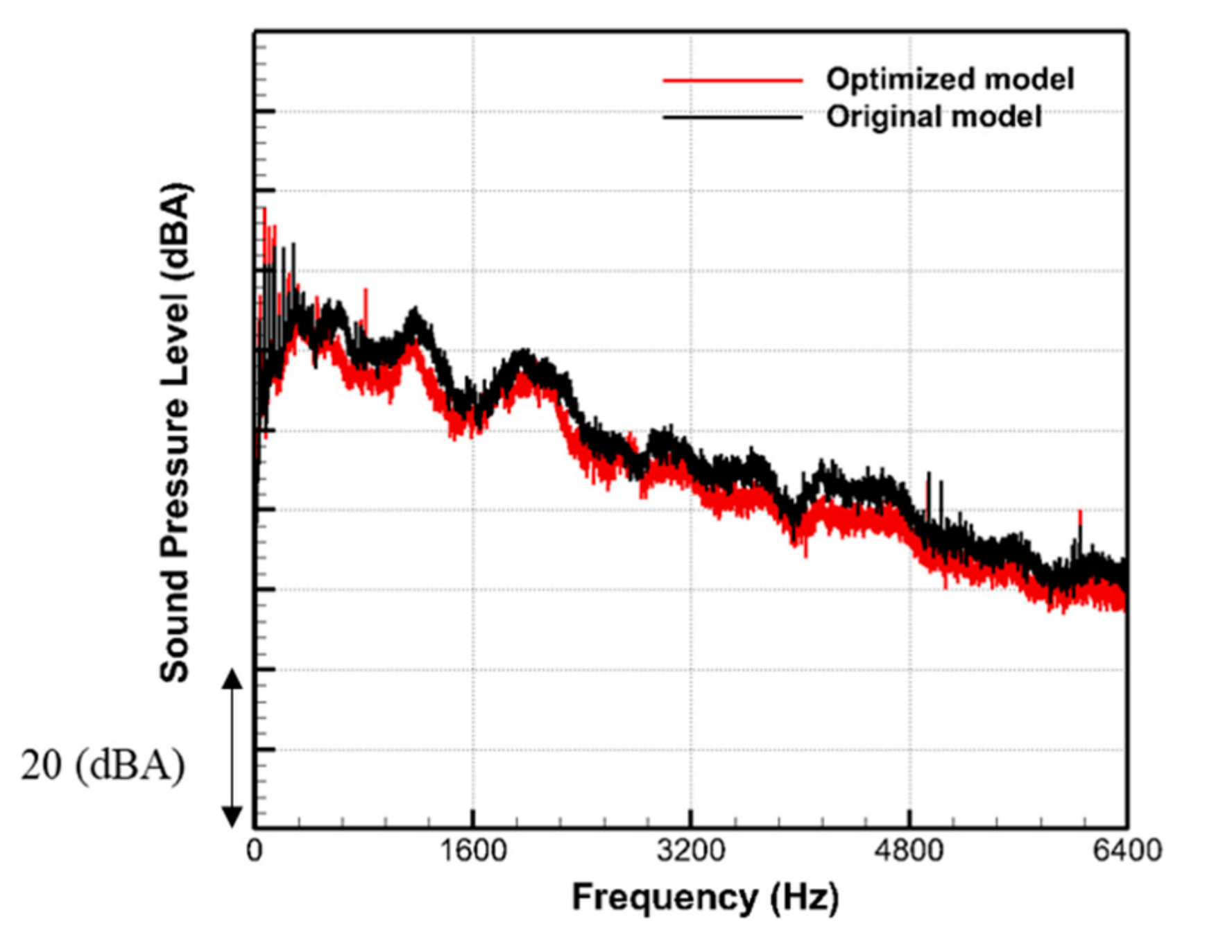
7. Experimental Validation of Optimized Design Using Engineering Samples

Flow and noise experiments are performed to validate the actual performance of optimized orifice for the axial-flow fan in the outdoor unit. The experimental set-ups for the evaluation of flow and noise performances are the same as those described in Section 3. The experimental results are summarized in Table 2.
As a result, the flow performance is increased by 2.1%, the sound pressure level is reduced by 2.8 dBA, and the input power is reduced by 4.0% at the targeted operating condition. Figure 24 compares the spectral sound pressure levels between the two models. It can be seen that the sound pressure levels of the optimized system are lower than those of the original one in the high-frequency broadband components.
To confirm the performances at the various operating conditions, the flow and noise experiments are carried out by varying the rotational speed of the fan. The volume flow rate and the sound pressure level measured are shown in Figure 25. It can be seen that the volume flow rate of the fan system using the optimized orifice is higher than the original one in the entire range of rotation speeds of the fan. In addition, the sound pressure levels of the optimized system are reduced in comparison with the original one in the entire range. Based on these measured data, it can be found that the aerodynamic noise of the outdoor unit with the optimized orifice is reduced by 2.9 dBA at the same volume flow rate. These measured data confirm the validity of the proposed optimum design of the orifice for the axial-flow fan in the outdoor unit.

8. Conclusions

In this study, the aerodynamic and aeroacoustics performances of the axial-flow fan system in the outdoor unit of the split-type air conditioner was investigated using the numerical and experimental methods. First, the virtual fan-performance tester (VFT) using the incompressible unsteady RANS solver was devised to investigate the detailed flow field driven by the axial-flow cooling fan in the outdoor unit of the air-conditioner. Its validity was confirmed by comparing the predicted P–Q curve with that measured using the fan-performance tester. To improve the flow and noise performance of the outdoor unit of the air-conditioner without changing the fan blade shape, the orifice shape is optimized. The geometry of orifice was divided into three sections: inlet, neck, and outlet. According to the role of each section, the curvature radius of the inlet, the height of the neck, and the angle of the outlet were selected as the independent variables for the optimization. The response surface method using these variables was carried out for the maximum flow rate. It was found that the axial-flow fan using the optimal shape of the orifice drove the airflow by 4.6% more than the existing one. The detailed analysis of the flow field showed that this improvement was achieved by reducing the vortex flow between the fan blade tip and the orifice. Finally, the flow and noise experiments using the prototype engineering sample manufactured using the optimized design showed that the flow rate is increased by 2.1%, the sound pressure level is reduced by 2.8 dBA, and the input power is reduced by 4.0% at the same rotational speed.

Author Contributions

C.C. provided the basic idea for this study and the overall numerical strategies. S.-Y.R. carried out the numerical simulations and worked on the analysis of numerical results. S.M.P. and Y.-C.A. Provided the basic concept of optimization. J.W.K. and B.I.P. carried out the experiments. S.K.O. administrated the project.

Funding

This research was supported by the Basic Science Research Program through the National Research Foundation of South Korea (NRF), funded by the Ministry of Education (NRF-2016R1D1A1A099 18456).

Acknowledgments

This work was supported by the ‘Human Resources Program in Energy Technology’ of the Korea Institute of Energy Technology Evaluation and Planning (KETEP), which granted financial resources from the Ministry of Trade, Industry & Energy, Republic of Korea (No. 20164030201230).

Conflicts of Interest

The authors declare no conflict of interest.

References

  1. Lee, S.; Heo, S.; Cheong, C. Prediction and reduction of internal blade-passing frequency noise of the centrifugal fan in a refrigerator. Int. J. Refrig. 2010, 33, 1129–1141. [Google Scholar] [CrossRef]
  2. Heo, S.; Cheong, C.; Kim, T.H. Development of low-noise centrifugal fans for a refrigerator using inclined S-shaped trailing edge. Int. J. Refrig. 2011, 34, 2076–2091. [Google Scholar] [CrossRef]
  3. Heo, S.; Cheong, C.; Kim, T. Unsteady Fast Random Particle Mesh method for efficient prediction of tonal and broadband noises of a centrifugal fan unit. AIP Adv. 2015, 5, 97–133. [Google Scholar] [CrossRef]
  4. Heo, S.; Ha, M.; Kim, T.H.; Cheong, C. Development of high-performance and low-noise axial-flow fan units in their local operating region. J. Mech. Sci. Technol. 2015, 29, 3653–3662. [Google Scholar] [CrossRef]
  5. Zhao, X.; Sun, J.; Zhang, Z. Prediction and measurement of axial flow fan aerodynamic and aeroacoustic performance in a split-type air-conditioner outdoor unit. Int. J. Refrig. 2013, 36, 1098–1108. [Google Scholar] [CrossRef]
  6. Jiang, C.L.; Chen, J.P.; Chen, Z.J.; Tian, J.; OuYang, H.; Du, Z.H. Experimental and numerical study on aeroacoustic sound of axial flow fan in room air conditioner. Appl. Acoust. 2007, 68, 458–472. [Google Scholar] [CrossRef]
  7. Wright, T.; Simmons, W.E. Blade sweep for low-speed axial fans. In ASME 1989 International Gas Turbine and Aeroengine Congress and Exposition; American Society of Mechanical Engineers: Amsterdam, The Netherlands, 1989. [Google Scholar]
  8. Ye, X.; Li, P.; Li, C.; Ding, X. Numerical investigation of blade tip grooving effect on performance and dynamics of an axial flow fan. Energy 2015, 82, 556–569. [Google Scholar] [CrossRef]
  9. Wang, H.; Tian, J.; Ouyang, H.; Wu, Y.; Du, Z. Aerodynamic performance improvement of up-flow outdoor unit of air conditioner by redesigning the bell-mouth profile. Int. J. Refrig. 2014, 46, 173–184. [Google Scholar] [CrossRef]
  10. Hu, J.; Ding, G. Effect of deflecting ring on noise generated by outdoor set of a split-unit air conditioner. Int. J. Refrig. 2006, 29, 505–513. [Google Scholar] [CrossRef]
  11. Jiang, C.L.; Tian, J.; Ouyang, H.; Chen, J.P.; Chen, Z.J. Investigation of air-flow fields and aeroacoustic noise in outdoor unit for split-type air conditioner. Noise Control Eng. J. 2006, 54, 146–156. [Google Scholar] [CrossRef]
  12. Korea Standards. Room air-conditioners, KS C 9306; Korean Standards Association: Seoul, Korea, 2002. [Google Scholar]
  13. Escue, A.; Cui, J. Comparison of turbulence models in simulating swirling pipe flows. Appl. Math. Model. 2010, 34, 2840–2849. [Google Scholar] [CrossRef]
  14. Yilmaz, H.; Cam, O. Effect of different turbulence models on combustion and emission characteristics of hydrogen/air flames. Int. J. Hydrog. Energy 2017, 42, 25744–25755. [Google Scholar] [CrossRef]
  15. Yakhot, V.; Orszag, S.A. Renormalization group analysis of turbulence. I. Basic theory. J. Sci. Comput. 1986, 1, 3–51. [Google Scholar] [CrossRef]
  16. Galván, S.; Reggio, M.; Guibault, F. Assessment study of K-ɛ turbulence models and near-wall modeling for steady state swirling flow analysis in draft tube using fluent. Eng. Appl. Comput. Fluid Mech. 2011, 5, 459–478. [Google Scholar] [CrossRef]
  17. Ffowcs-Williams, J.E.; Hawkings, D.L. Sound Generation by Turbulence and Surfaces in Arbitrary Motion. Philos. Trans. R. Soc. Lond. Ser. A. Math. Phys. Sci. 1969, 264, 321–342. [Google Scholar] [CrossRef]
  18. Ren, G.; Heo, S.; Kim, T.H.; Cheong, C. Response surface method-based optimization of the shroud of an axial cooling fan for high performance and low noise. J. Mech. Sci. Technol. 2013, 27, 33–42. [Google Scholar] [CrossRef]
  19. Montgomery, D.C. Design and Analysis of Experiments, 6th ed.; John Wiley and Sons: New York, NY, USA, 2005. [Google Scholar]
  20. Khuri, A.I.; Cornell, J.A. Response Surfaces, 2nd ed.; Marcel Dekker: New York, NY, USA, 1996. [Google Scholar]
Figure 1. Internal structure of targeted outdoor unit and main parts: (a) internal structure of outdoor unit, (b) main parts, and (c) axial-flow fan.
Applsci 09 05207 g001
Figure 2. Schematic diagram of the actual fan-performance tester.
Applsci 09 05207 g002
Figure 3. Measured overall sound pressure level versus rotating speed.
Applsci 09 05207 g003
Figure 4. Various virtual fan testers used for grid-refinement study.
Applsci 09 05207 g004
Figure 5. Comparison of predicted P–Q curves with experimental ones.
Applsci 09 05207 g005
Figure 6. Comparison of predicted noise spectrum with experimental ones.
Applsci 09 05207 g006
Figure 7. Vector fields of fluid velocities on vertical cross-sectional plane passing rotating center of fan blades with zoomed plot around motor mount.
Applsci 09 05207 g007
Figure 8. Vector fields of fluid velocities on vertical and horizontal cross-sectional planes passing heat sink.
Applsci 09 05207 g008
Figure 9. Vector fields of fluid velocities on the vertical cross-sectional plane passing rotating center of fan blades around the orifice.
Applsci 09 05207 g009
Figure 10. Iso-contours of static pressure on horizontal cross-sectional plane passing rotating center of fan blades.
Applsci 09 05207 g010
Figure 11. Iso-contours of velocity magnitudes on horizontal cross-sectional plane passing rotating center of fan blades.
Applsci 09 05207 g011
Figure 12. Directivity of overall sound pressure level.
Applsci 09 05207 g012
Figure 13. Shape of the orifice.
Applsci 09 05207 g013
Figure 14. Design parameters for optimization of orifice shape.
Applsci 09 05207 g014
Figure 15. The relation between flow rate and each design factor.
Applsci 09 05207 g015
Figure 16. Optimized shape of orifice.
Applsci 09 05207 g016
Figure 17. Contours of velocity magnitudes of the optimized orifice.
Applsci 09 05207 g017
Figure 18. Snapshots of vector fields of fluid velocities: (a–c) for original orifice; (d–f) for optimized orifice.
Applsci 09 05207 g018
Figure 19. Snapshots of vector fields of fluid velocities at fixed inlet & neck design factors: (a–d) for the case of (R, H, θ ) = (18, 28.8, 55); (e–h) for the case of (R, H, θ ) = (18, 28.8, 0).
Applsci 09 05207 g019
Figure 20. Comparison of radial loading on orifice between original and optimized ones.
Applsci 09 05207 g020
Figure 21. Comparison of axial loading on the orifice between original and optimized ones.
Applsci 09 05207 g021
Figure 22. Comparison of predicted sound pressure level spectrum between original and optimized models.
Applsci 09 05207 g022
Figure 23. Comparing of predicted directivity between original model and optimized models.
Applsci 09 05207 g023
Figure 24. Comparison of sound pressure spectral levels predicted for optimized and original models.
Applsci 09 05207 g024
Figure 25. Comparison of performances between optimized and original systems at the various rotating speeds of fan: (a) volume flow rate and (b) overall sound pressure levels.
Applsci 09 05207 g025
Table 1. Factors and level for optimization of orifice shape
FactorsLevel
1 01
R mm 12.31823.7
H mm 827.547
θ   ( deg 13.128.844.5
Table 2. Summary of experimental results at operational speed.
PerformancesOriginal OrificeOptimized Orifice
Volume flow rateA1.02A
Overall SPL (dBA)BB-2.8
Input power (%)C0.96C

