1. Introduction
Nowadays, manipulators have an increasing degree of requirement in many fields, since grasping operations [
1,
2] with manipulators can be competent for various works that substitute human beings. A redundant manipulator which possesses more DOF (degree of freedom) and dexterity in three-dimensional space has a better performance in self-perception and self-learning when in an unstructured environment and amongst clutter. The ability of autonomy is increasingly becoming more and more important for manipulators in complex scene applications. Thus, it is significant for redundant manipulators to possess the ability of self-recognition, especially for grasping operations.
To achieve self-recognized grasping operation, redundant manipulators need to complete object detection, object location, and grasp planning autonomously. In object detection, the target object is distinguished from others and the environment. In terms of the object location, the 3D (three dimensional) position and orientation angle of the target object are obtained in a pixel coordinate system. Then, via pose transformation, a joint angle sequence is derived for manipulator control via the pose (position and orientation) expressed in the pixel coordinate system.
Vision systems which can obtain abundant information about the present environment have already been integrated in manipulator grasping operation [
3,
4]. In the industry field, templates of objects (components or work piece) are made in advance. Features such as SIFT (scale-invariant feature transform) [
5] and SURF (speeded-up robust features) [
6] are extracted from the image to achieve shape-matching [
7]. Since the position of an object is traceable in the workbench, methods such as the optical flow method [
8] are applied for simplified location and motion tracking. However, these methods rely on the known classification and position of objects, and they cannot be adapted for unstructured environments and those where clutter objects with unknown information exist. Indeed, with vision systems, target object detection and location can be achieved preferentially for self-recognition grasping operation.
Benefit from the studies on deep learning, CNNs [
9,
10] (convolutional neural networks) have been used to achieve object recognition, leading to various methods such as image classification [
11,
12], object detection [
13,
14], semantic segmentation [
15,
16], and instance segmentation [
17,
18]. Many frameworks of instance segmentation have been proposed, such as SDS (simultaneous detection and segmentation) [
19], CFM (convolutional feature masking) [
20], MNC (multi-task network cascades) [
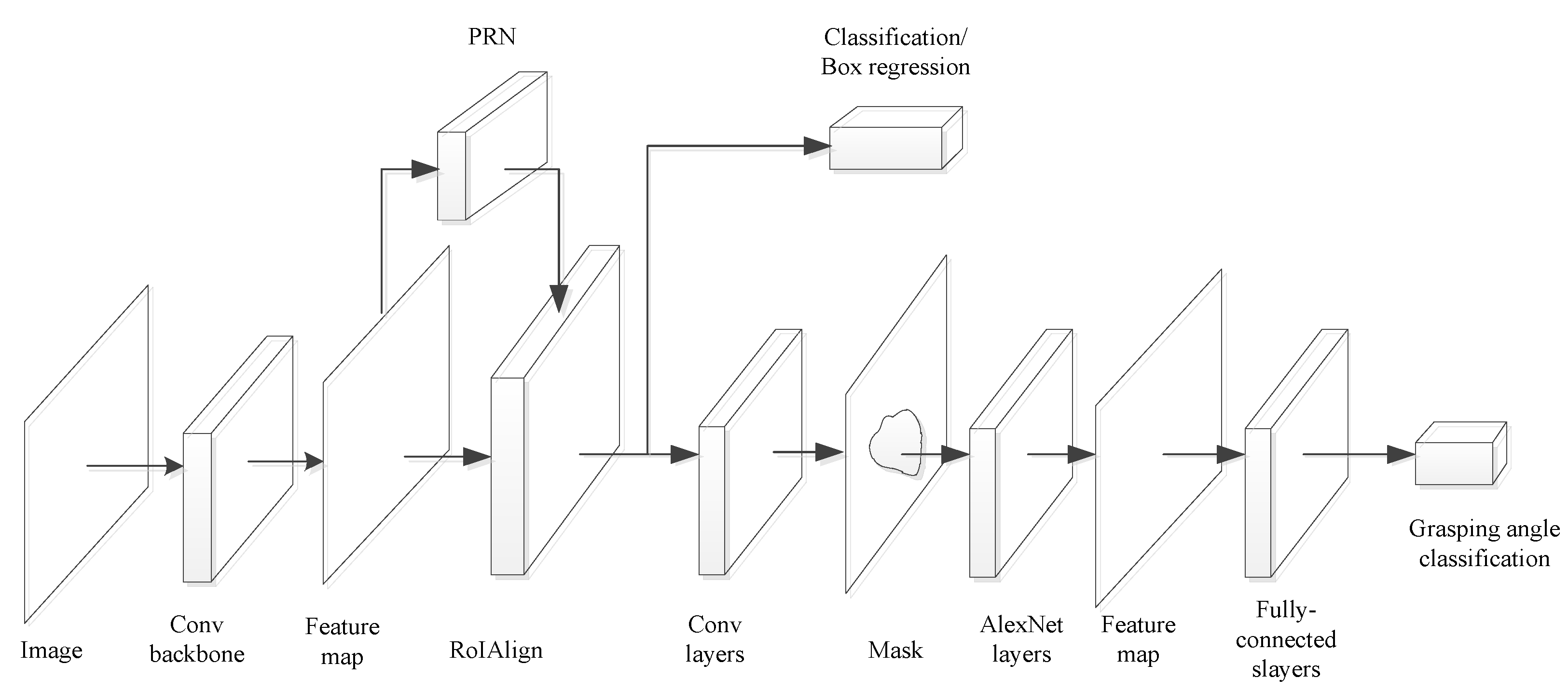
21], and so on. Mask R-CNN (regions with CNN features) [
22], which achieves object classification and contour description simultaneously, can accurately determine target objects from an unstructured environment. Besides, the contour has a smaller region than the classification box for object pose estimation.
After obtaining the contour and classification of an object by instance segmentation, the location of the object should be determined. In traditional methods, an RGB image is used to achieve pose estimation for the target object by matching local features [
23,
24]. However, this is worse in performance when locating textureless objects. However, RGB-D images, which describe the depth information with a point cloud, can directly obtain the 3D position objects [
25,
26,
27]. The benefit from grasping databases [
28,
29,
30] and orientation estimation is converged into an classification problem [
31] via discretizing orientation angles. As a result, the pose of target object can be located in the pixel coordinate system.
Pose transformation can be divided into two steps. Firstly, the pose expressed in pixel coordinates is transferred into Cartesian coordinates via the parameters of the camera, which is explained in [
32,
33]. Second, the pose is transferred into the joint space of the manipulator via inverse kinematics. The inverse solution problem [
34] is an old question for robotics, which can be solved in either the velocity or position forms. The inverse solution in velocity form (ISVF) relies on the Jacobian matrix of the manipulator, which represents the relationship between the joint velocity and the velocity of the end-effector. In ISVF, an initial configuration should be set, then simulated, where planning is carried out from the initial configuration to the pose of the object. The angles of each joint are converged by an integral of joint velocity at each motion interval. The process is fussy and costly in time, making ISVF suitable for offline trajectory planning.
The inverse solution in position form (ISPF) can obtain joint angles directly, and can generally be divided into numerical [
35] and geometric methods [
36]. However, the numerical method presents an abundant computation cost, leading to poor real-time adaption. Additionally, it often falls into a local optimum. The geometric method is only effective for low DOF manipulators (i.e., those not exceeding 6-DOF). For manipulators with a spatial redundancy (i.e., those with at least 7-DOF), this method is not compatible. Indeed, there are infinite solutions for a particular pose with redundant manipulators (DOF > 6). Less methods can achieve the expression of all feasible solutions, rapid calculation, and optimal solution selection simultaneously, which are imperative for pose transformation in self-recognized grasping operation. Thus, a method of ISPF, which can express the whole solution set rapidly and build up a rule selecting the global optimal solution, is significant for redundant manipulator application in unstructured environments and environments with clutter.
The contribution of the paper is exposing the process of self-recognition grasping operation with a vision-based spatially redundant manipulator. Instance segmentation is used to distinguish the object and describe the contour. Within the contour, pose estimation is carried out via a grasping network. On this basis, a method is proposed to calculate the inverse solution in position form to transfer the pose into the joint space of the manipulator for direct motion control.
The
Section 2 shows the process of the vision-based self-recognized grasping operation, including the framework of instance segmentation, the grasping network of pose estimation, and the methods of pose transformation. In the
Section 3, the inverse method of ISPF is described in detail. In the
Section 4, experiments on self-recognition grasping operation are carried out. The process of self-recognition is verified and the method of ISPF is proven to be effective for real-time calculation and global optimal solution selection. The
Section 5 presents our conclusion.
3. The Method of ISPF for Pose Transformation
The process of the self-recognized grasping operation is presented above. Instance segmentation, pose estimation, and pose transformation, are all indispensable in achieving self-recognition. However, the traditional method of inverse kinematics in Equation (2) is not adaptable. A new method is required to achieve the expression of all feasible solutions, rapid calculation, and optimal solution selection. In this section, a method of ISPF which relies on manipulator configuration simplification is proposed. The configuration of the redundant manipulator is simplified based on the possible locus circle of the elbow node. Then, the relationship of joint angles is derived analytically, and all the feasible solutions can be calculated. By introducing an optimal factor, the corresponding optimal solution can be selected.
3.1. Manipulator Simplification and Parameters Definition
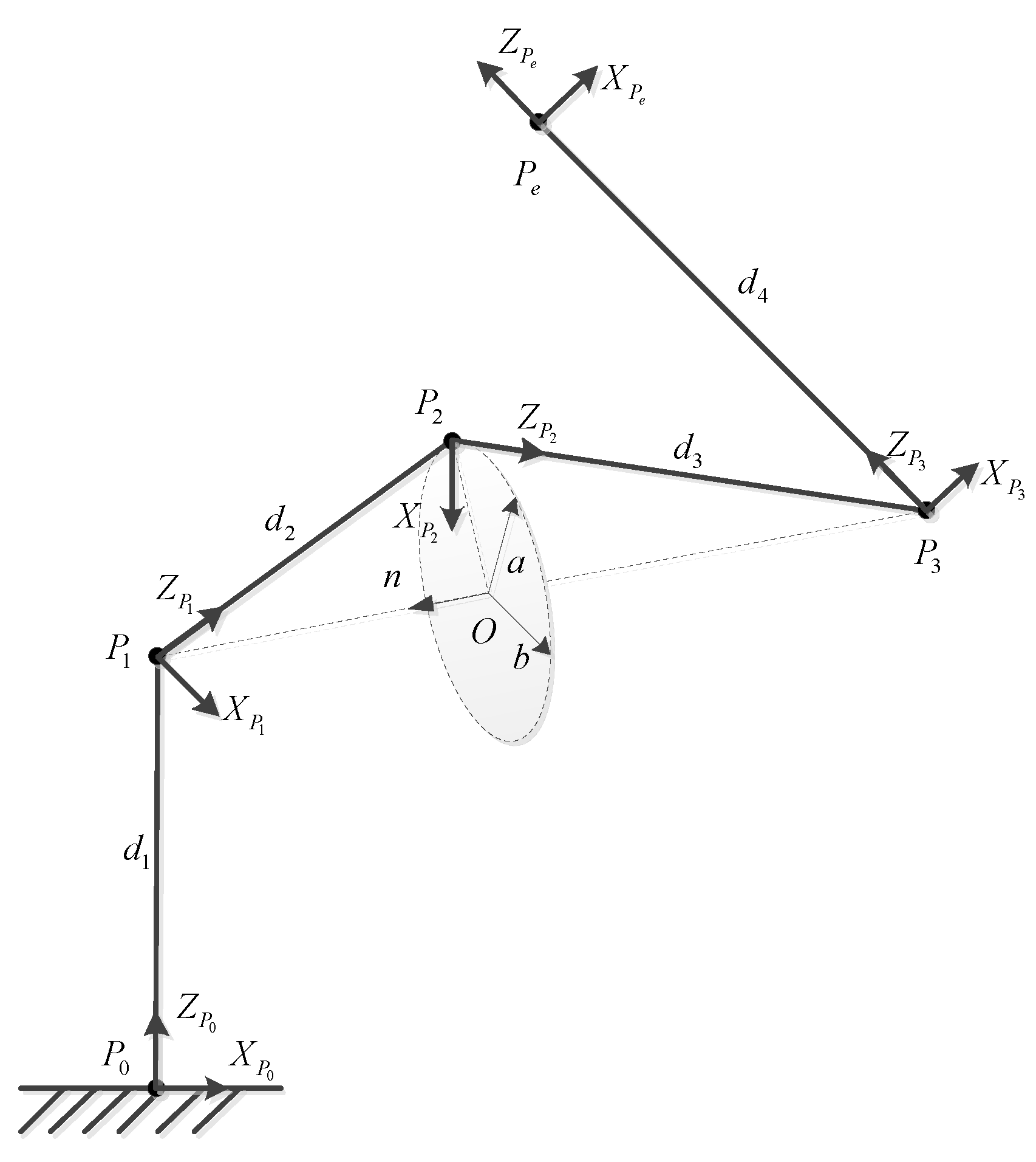
Considering the configuration of a 7-DOF manipulator, it can be simplified into four parts according to three nodes, namely, the wrist, elbow, and shoulder, which are labeled as
. The node of the base and the node of the end-effector are labeled as
respectively. The simplified configuration is shown in
Figure 3. In the figure, the possible position of
forms a circle, which is named as the locus circle of
. The locus circle has the following properties:
After simplification, the parameters of manipulator can be defined as follows:
: The position of the end-effector of the manipulator.
: The attitude matrix of the end-effector of the manipulator.
: The joint coordinate system, , where represents the base coordinate system, represents the coordinate system of the end-effector, and represents the coordinate system at node , .
: Transformation matrix between the and coordinate system.
: The position coordinate of the node, .
: The center of locus circle of .
: Arbitrary vector in the plane of locus circle.
: Vector in the plane of locus circle, fulfilling .
: Normal vector of the plane of locus circle.
: The distance between node and the center of circle .
: The distance between the and node.
: The vector between the and node.
According to the configuration of manipulator shown in
Figure 3, the joint angles are divided into three groups, which are respectively derived in the following section.
3.2. Feasible Solutions Expression
Since nodes
and
are located on a rigid link, the attitude of the two nodes are consistent. However, the positions of the two nodes are different. According to
, they can be obtained as follows:
Then, the position of
can be obtained as follows:
where
. Here, we define the locus circle of node
as follows:
where
represents the radius of the circle and
represents the phase of circle. In order to solve Equation (5), the coordinate of the center,
, should be firstly obtained. Geometrically,
Now, the distance between node
and
can be obtained as follows:
Since the radius of circle , according to Equation (8), the coordinate value of the center is obtained.
Meanwhile,
can be calculated as follows:
By substituting Equations (9) and (10) into Equation (5),
can be calculated. Accordingly, the coordinate values of nodes
are solved, and the joint angles of
can be expressed as follows:
Here, we define the plane as . Since can be calculated, is determined by and the plane changes with . Here, can be treated as the dihedral angle between and the plane . When , can be obtained according to Equation (11). Here, can be calculated.
where
. The normal vector
of plane
and normal vector
of plane
can be expressed as follows:
Then, the dihedral angle, namely,
, can be calculated:
After obtaining
,
can be calculated. According to
, we define
, where
represents the element of
row and
column.
can be calculated as follows:
So far, is derived by Equations (11), (14), and (15), with which all the feasible solutions for a particular grasping pose can be obtained.
3.3. The Optimization of ISPF
In
Section 3.2, the joint angle sequence
varies with the phase angle
of the locus circle. In other words,
can be expressed as the function of phase angle
of the locus circle:
The relationship between and is implicitly represented by the function . When given the pose of the target object, all feasible solutions in the position form can be calculated. For direct control, the optimal solution should be selected, which can be treated as an optimization problem with a single objective. The optimal solution selection is discussed during grasping experiments in the next section.
4. Simulation and Experiments
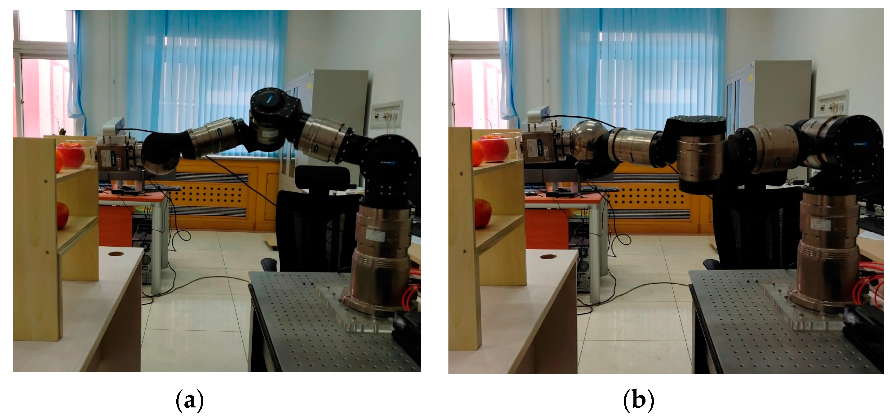
The redundant manipulator used in the paper is a 7-DOF serial manipulator made by SCHUNK, whose joint coordinates and configuration are shown in
Figure 4. The DH (Denavit-Hartenberg) parameters are listed in
Table 1. A ZED camera is set on the end-effector of the manipulator to obtain a RGB-D image. With the manipulator, we used five experiments to validate the proposed methodology and system. Two experiments of instance segmentation and pose estimation based on vision system were carried out to obtain the pose of the target object. Three experiments of pose transformation were carried out to verify the method of ISPF in achieving efficient feasible solution calculation, selecting the optimal solution and showing advantages compared to solutions obtained by the iteration method.
4.1. Experiment on Finding and Locating Target Object
For the self-recognized grasping operation, the primary step is to the distinguish target object from the unstructured environment. Here, we set some fruit on the shelf shown in
Figure 5a. There are two kinds of fruit (an apple and orange), and two apples were placed on different layers. We would like the manipulator to distinguish the three objects and grasp the upper apple by itself.
The experimental scene obtained via a camera is shown in
Figure 5b. The shelf was set as an obstacle and limitation to the workspace of the robot in its grasping operation. Different objects belonging to the same category (apple) were set to confuse the recognition of the target object. The background is a common lab, which is considered as clutter, confusing the feature detection and pose estimation. The experimental scene can be treated as a typical unstructured environment.
The instance segmentation algorithm is devoted to mark the object and provide a result, as shown in
Figure 5c. The fruit on the shelf can be clearly marked by category, and the two apples are also distinguished with different colors. The confidence coefficient of each object is labeled in the figure, and the target apple had the highest confidence coefficient, which was 0.90. Besides, the confused background can be almost eliminated via instance segmentation. As a result, the target apple is clearly recognized for further operation.
After finding the target apple, the position was detected as the center of the contour shown in
Figure 5c. The orientation for grasping was treated as a classification problem, based on the grasping network described in
Section 2. The contour was divided into 36 parts around the circumference, where each part is equal to a
angle, turning the orientation estimation into a 36-way binary classification problem. The orientation estimation result is shown in
Figure 5d. The orientation angle of the target apple was classified as
.
By taking a photo via the vision system, the manipulator can find the target object from the unstructured environment and obtain the contour of the target object, then obtain the position and orientation angle autonomously. According to the experiment, the efficiency of instance segmentation and grasping network is verified via self-recognized grasping. The benefit from instance segmentation and grasping orientation estimation was used, concerning the contour of the target object. The contour marked by instance segmentation is more accurate than bounding box classification, which greatly reduces the range and time cost for the grasping network to estimate the grasping orientation.
4.2. Feasible Solutions Based on the ISPF Method
By the experiments in
Section 4.1, the position of target object and grasping orientation angle were obtained. The pose of the end-effector, namely,
, could be obtained according to Equation (1). With the method of ISPF, kinematics and transformation matrices between joint coordinates were calculated by the DH parameters listed in
Table 1. Then, solutions for successful grasping could be obtained by changing the value of phase angle
in
. In
Figure 6, four representative solutions (obtained at
,
,
, and
) are shown to achieve grasping operation.
From
Figure 6, all four configurations of the redundant manipulator could successfully achieve grasping operation. Different joint angles correspond to different joint positions and manipulator configurations. By varying
, which varies in
, at an interval of
, 18 groups of inverse solutions were calculated, and the corresponding configurations are shown in
Figure 7.
Figure 7a is a general view of the solutions, and
Figure 7b is viewed from the Y-Z plane. It clearly shows that the possible positions of
form a circle. When
varies, all the feasible solutions can be obtained and represented, as shown in
Figure 7a. This verifies with the method of ISPF, where the manipulator can efficiently calculate the entire feasible solution set. Besides, the shape formed by the possible solutions confirms the validation of manipulator simplification and the locus circle application outlined in
Section 2.
4.3. The Optimal Solution with ISPF
During , countless solutions exist which can achieve the same pose at the end-effector of the redundant manipulator. However, for grasping operation, only one group of solutions are needed. In order to find the optimal solution, an optimizing factor can be introduced. Manipulability is an important and common factor representing the dexterity of robots. The optimal solution, when determined by manipulability, has a better adaption for the unstructured environment, especially in terms of humanoid control and dexterous manipulation.
In Equation (17),
represents the Jacobian matrix of the manipulator at joint angles
, where
. It can be calculated by the DH parameters of the robot and joint angles
.
represents the manipulability of manipulator. Since
has been derived by the ISPF method, corresponding manipulability can be obtained during
, according to Equation (17). The variation of manipulability related to
is shown in
Figure 8.
From
Figure 8, the maximum value of manipulability can be found at
, and the corresponding solution is
. The minimal value of manipulability is at
, where the corresponding solution is
. The configurations at the minimum and maximum of manipulability are shown in
Figure 9. Although the numerical difference of manipulability is not obvious, the configurations have a wide difference at the minimum and maximum of manipulability. Through the introduction of manipulability, the most dexterous grasping configuration can be selected from all the feasible solutions, with which dexterous grasping manipulation can be achieved.
Via the introduction of manipulability, manipulation can be expressed as a single object optimization problem of obtaining the optimal solution for self-recognized grasping operation.
With Equation (18), a unique value can be obtained to achieve dexterous self-recognized grasping operation with a redundant manipulator. Additionally, other optimal factors, such as the optimal torque, least time cost, and so on, can be introduced to replace manipulability in Equation (18), which will greatly expand the ISPF method in achieving various optimizations for various grasping operation requirements.
4.4. Comparison with the Iteration Method
The iteration method can also achieve pose transformation from the end-effector of the manipulator to joint angles and obtain a group of values for grasping operation. However, it requires a proper initial configuration. If the initial configuration is not reasonable, no feasible solution can be reached. When the initial configuration is proper, a group of joint angles can be iterated and converged. In this part, the inverse solutions obtained with iteration method are compared with ones obtained with the ISPF method.
In
Table 2, 6 groups of initial configurations are listed to calculated joint angles with the iteration method. For the 1st group, the inverse solution cannot be obtained due to an unreasonable initial configuration. For the other groups, inverse solutions can be converged. The manipulability of these solutions were calculated to compare the solution calculated by the ISPF method, which is shown in
Figure 10.
In
Figure 10, the manipulability of each solution calculated by the iteration method is smaller than the solution calculated by the ISPF method at
. Although solutions can be obtained by the iteration method, they can hardly be optimal. For self-recognized grasping operation in unstructured environments, various constraints should be guaranteed. The introduction of manipulability makes the manipulator achieve singularity avoidance and joint limit avoidance, leading to better adaption than with the iteration method in unstructured environment applications. Besides, considering the limit of the unstructured environment on the workspace of the manipulator, it is convenient for the ISPF method to adjust feasible solutions achieving obstacle avoidance.
With the experiment, the efficiency of the ISPF method in obtaining the optimal solution for self-recognition grasping operation was verified. Compared with the iteration method, the ISPF method requires no default initial configuration. All the feasible solutions can be calculated, and the optimal one can be selected by introducing an optimal factor. Additionally, it is conveniently programmed with a high computational efficiency, supporting self-recognized grasping, making it a better choice than the iteration method in achieving pose transformation.
5. Discussion and Conclusions
In order to achieve self-recognized grasping operation with a redundant manipulator in an unstructured environment with clutter, the processes of instance segmentation, pose estimation, and pose transformation are described in the present paper. The three processes are indispensable, with which the manipulator can find, locate, and grasp target objects using its vision system, without any outside help. With instance segmentation, different categories of objects can be precisely distinguished with a high confidence coefficient, and the contours of objects can be clearly described. As a result, the range is precisely limited for highly efficient and accurate pose estimation. Via pose estimation with a grasping network, grasping attitude estimation is transferred into a multi-way classification problem, and the attitude represented by the orientation angle is conveniently transferred to a pose in Cartesian coordinates for grasping control. The two processes can work spontaneously once a RGB-D image is obtained by the vision system.
For pose transformation, we propose an inverse solution method at the position form to make it adaptable for self-recognition. The ISPF method requires no default initial configuration and can represent all of the feasible solutions. Besides, by introducing an optimal factor of manipulability, the optimal solution can be selected, achieving humanoid control and dexterous manipulation. Besides, the optimal factor can be replaced according to requirement of optimal control. The ISPF method can be expanded for various optimizations, such as optimal torque, least time cost, and so on. This validates the universality and extendibility of the ISPF method in the optimal control of robots. Further, the characteristic of being conveniently programmed with high computational efficiency makes it quite suitable for self-recognized grasping and real-time manipulator control.


