Design and Implementation of a Monitoring System Using Optical Camera Communication for a Smart Factory


Abstract
:1. Introduction
- Visible-light wave bandwidth is more than 1000 times the RF bandwidth.
- Visible light waves do not negatively affect human health [4], while RF waves generate electromagnetic interference, which not only reduces the performance of the system but also affects human health.
- Visible light waves are more efficient and secure if the channel model achieves line-of-sight (LOS) transmission.
- Existing VLC modes available in the IEEE 802.157-2011 standard [6].
- OCC: baseband modulation techniques that use cameras or image sensors to receive signals from a light source.
- Light-emitting diode identification (LED-ID): communication techniques that use photodiodes at low speeds, with data rates below 1 Mbps at the physical layer.
- High-speed Light Fidelity (Li-Fi): high-rate photodiode modulation techniques with data rates exceeding 1 Mbps at the physical layer. Li-Fi technologies utilize optical orthogonal frequency division multiplexing modulation.
2. Our Contributions
- Multi-users detection support: the selection and initialization of links of interest among thousands of artificial light sources are obstacles to be eliminated. Rx can detect active light and initialize a connection within the allowed delay time. The conditional method for object detection is based on a conditional computer vision (CV), but this reveals some disadvantages. For instance, CV can detect exactly which objects seem to improve the OCC link setup, but this is complex and has a long processing time delay. As such, we need another technique that can facilitate quick detection and suits the OCC system. Moreover, RoI signaling techniques support the OCC system, as has already been presented in IEEE 802.15.7m. Kookmin University and Intel have contributed to this concept, during meetings of the IEEE 802.15.7m Task Group. A camera with an RoI mode is permitted to set up the communication link for better quality with a shorter time delay.
- Support for all types of commercially available camera: the method of using OOK modulation for the OCC system can be applied to both the rolling-shutter camera and global-shutter camera. RoI signaling can similarly be applied to both the rolling-shutter camera and global-shutter camera.
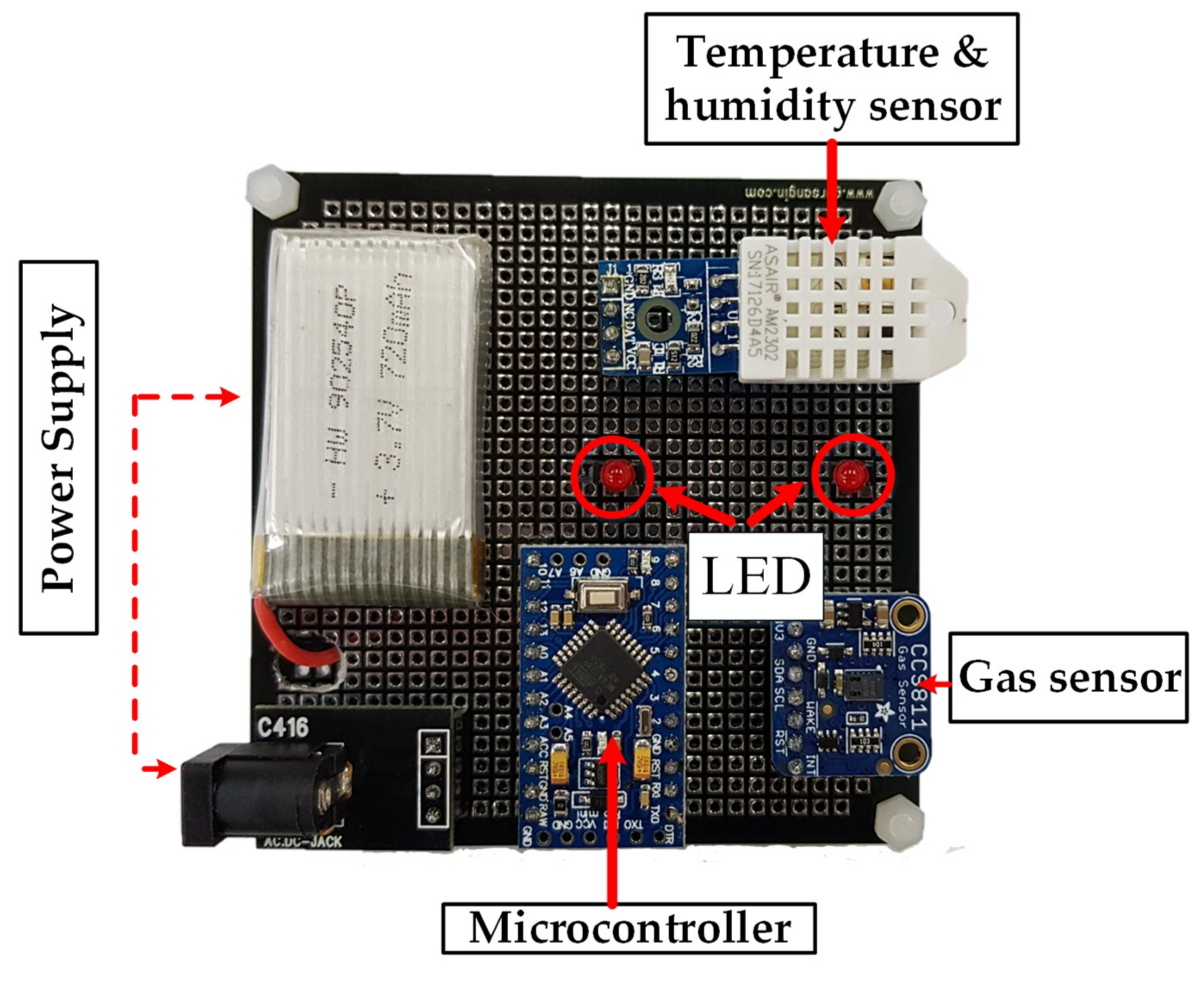
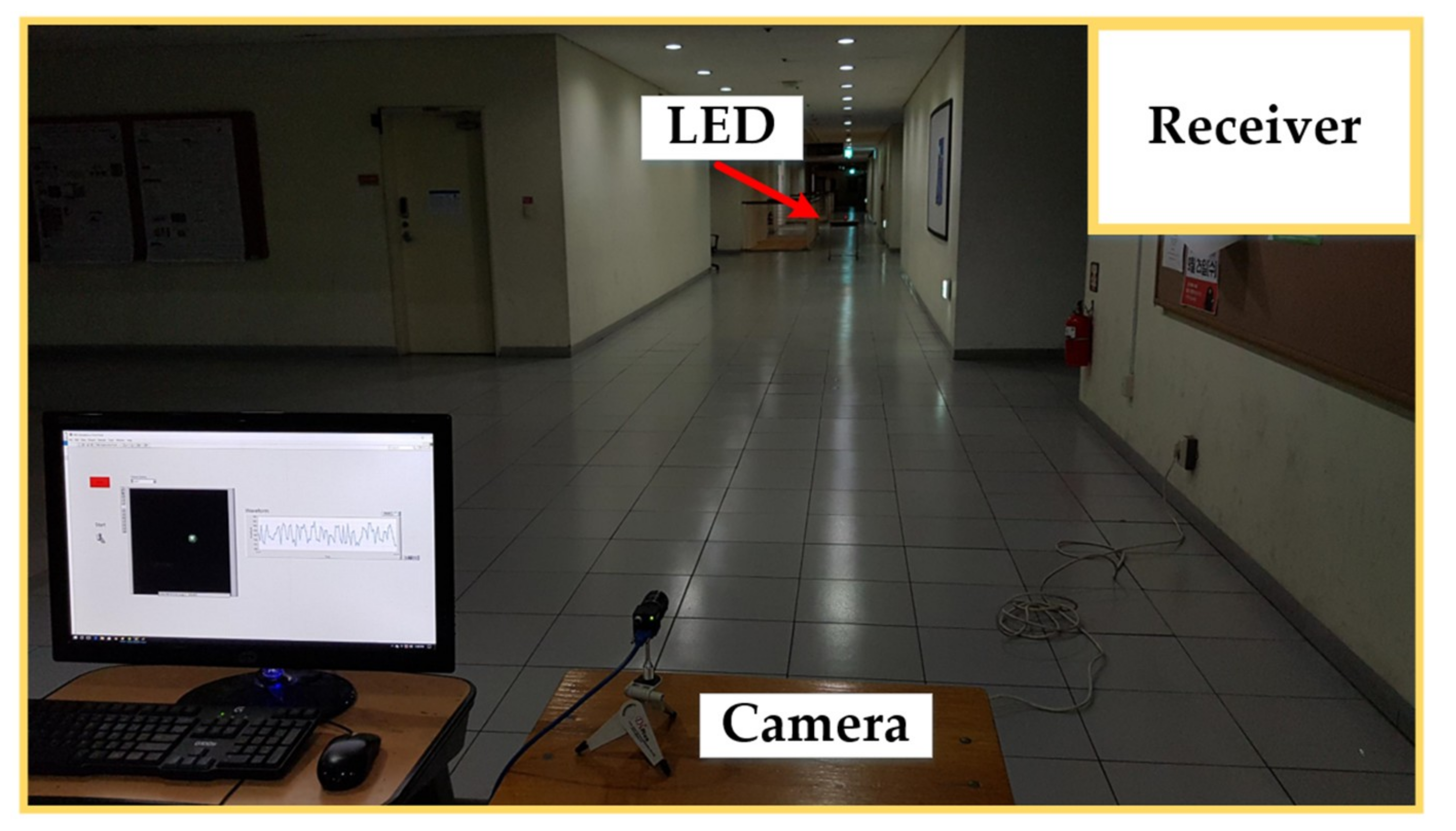
- Low power consumption and low cost: using small LEDs to transmit the environment parameters with a sleep mode significantly reduces power consumption, compared with RF technologies. Consequently, the module in the transmitter side can operate for long periods of time without the need for frequent battery replacement. Furthermore, the system’s design is very cost-efficient. The transmitter side has a Microcontroller (MCU), sensors, and small LEDs for the transmitter. The receiver side in this proposed scheme is compatible with all types of cameras, including CCTVs and webcams.
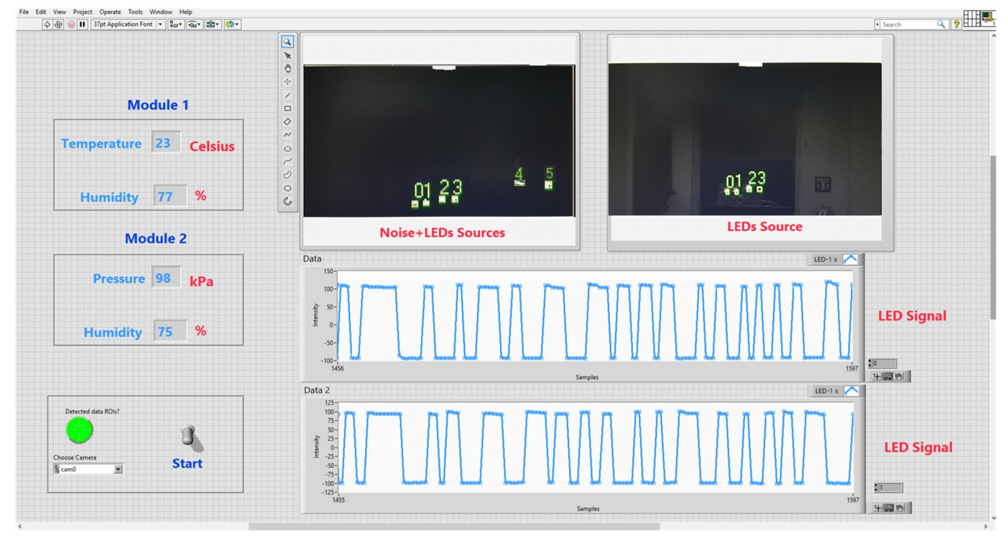
- Eliminate the noise light source: RoI technology helps to detect the position of light sources in the image. However, it is necessary to differentiate between the noise signal and the Tx signal. Therefore, after using the RoI technique to detect objects, the sampling signals from all objects are checked.
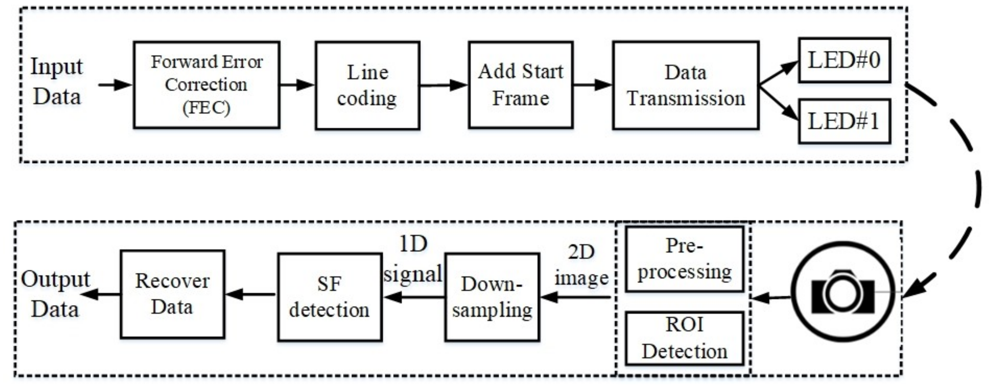
3. System Architecture
3.1. Line Coding
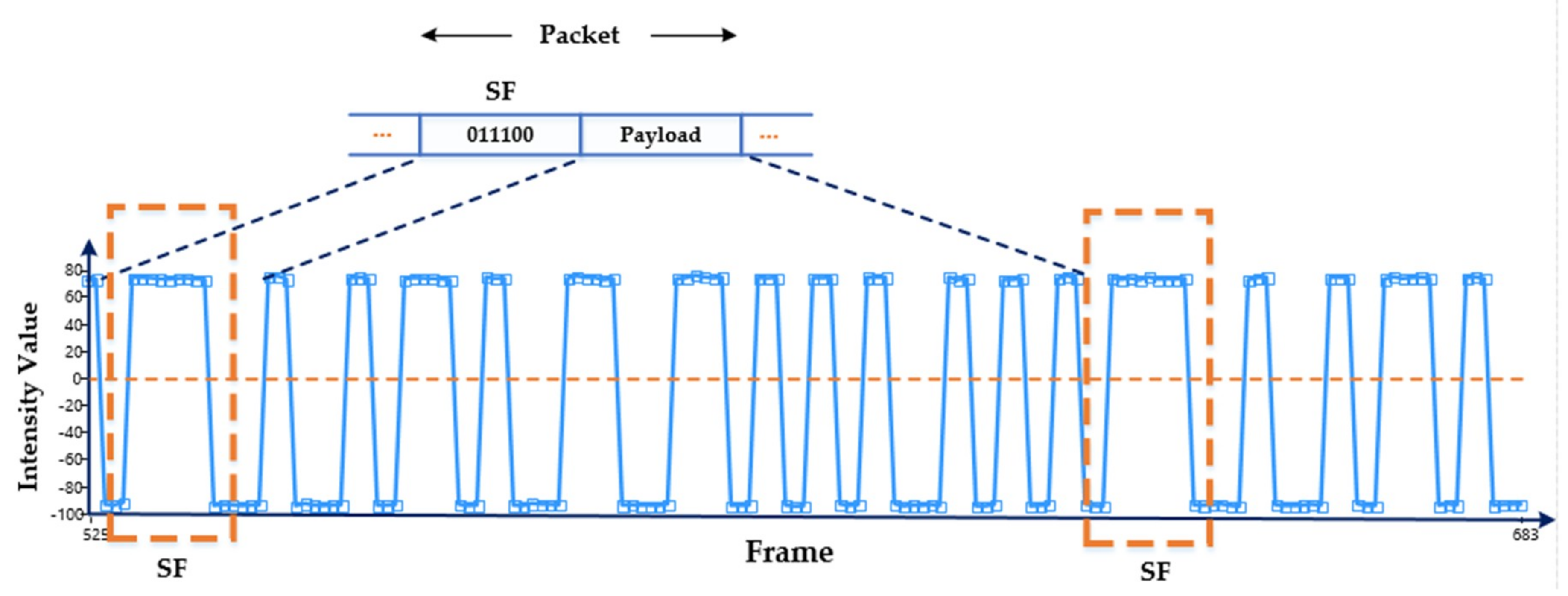
3.2. Add Start Frame
3.3. RoI Detection
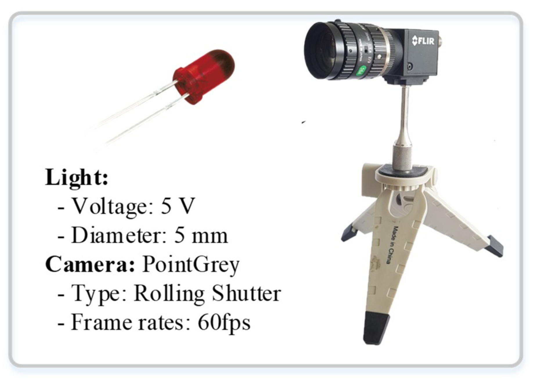
4. Implementation
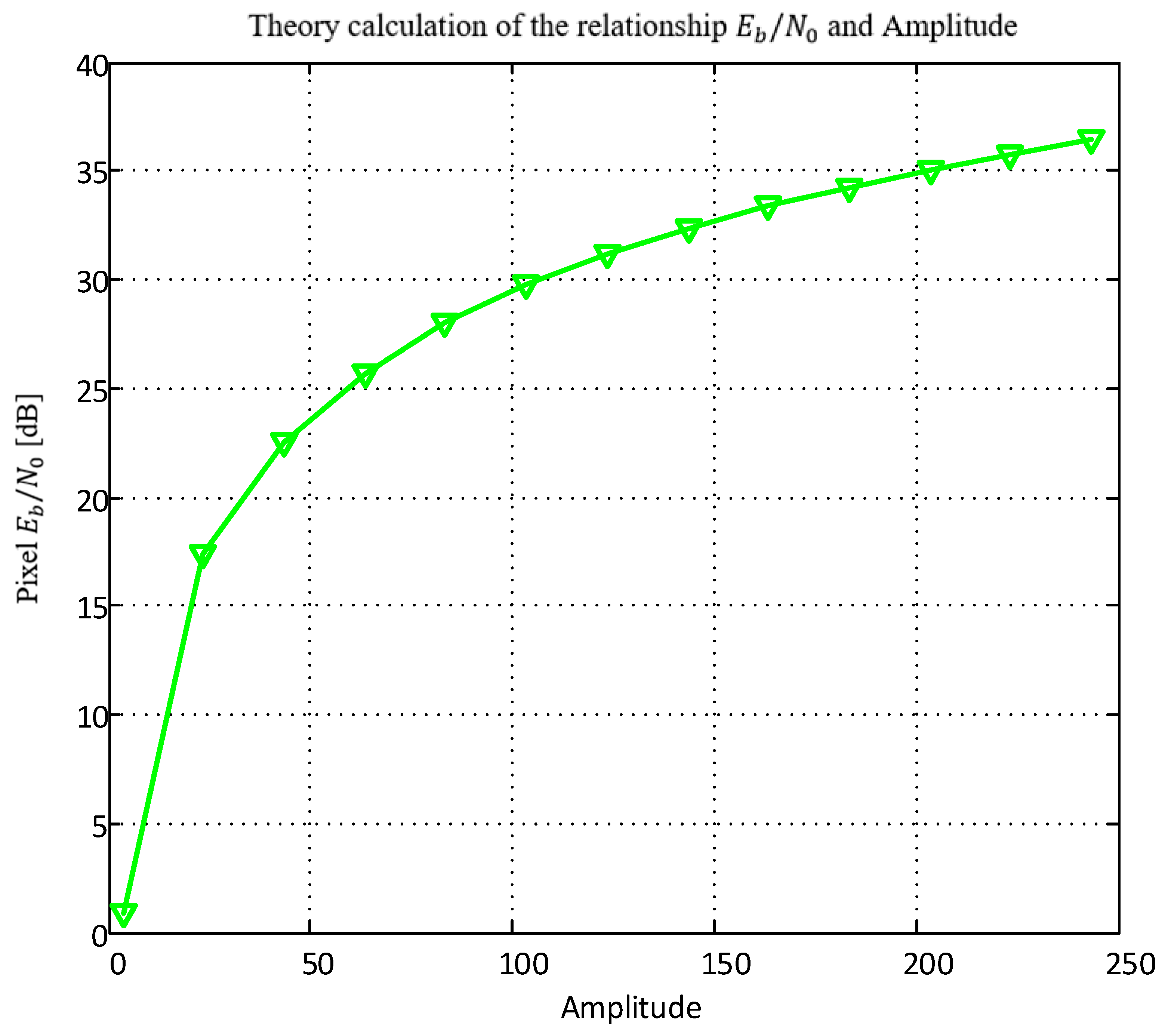
4.1. Pixel Eb/N0 Computation and Noise Modeling
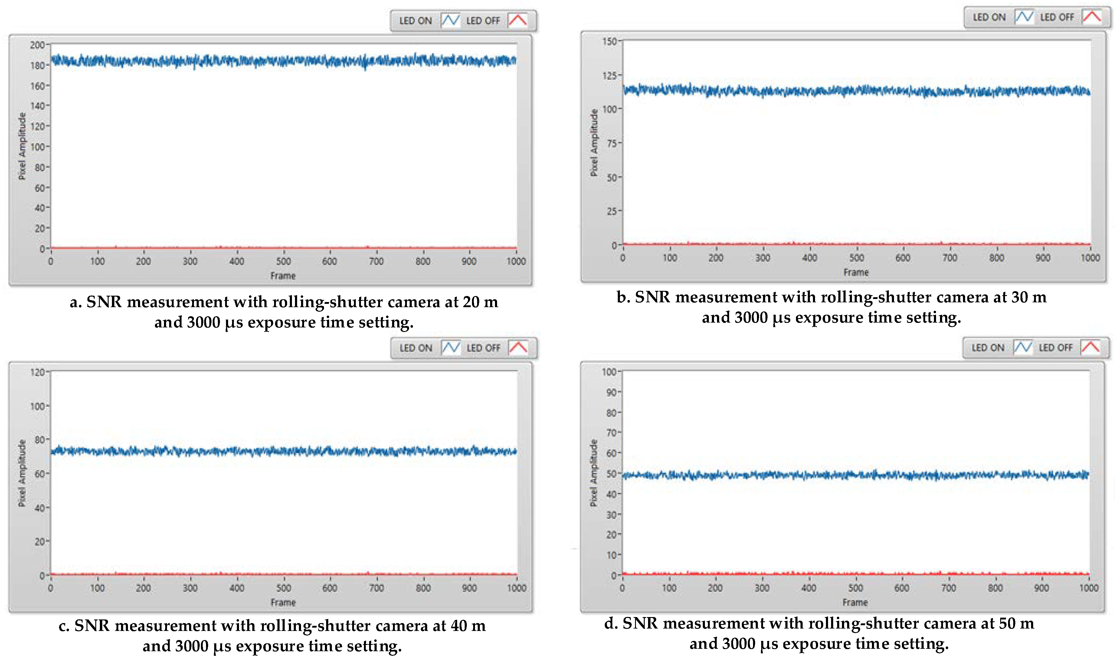
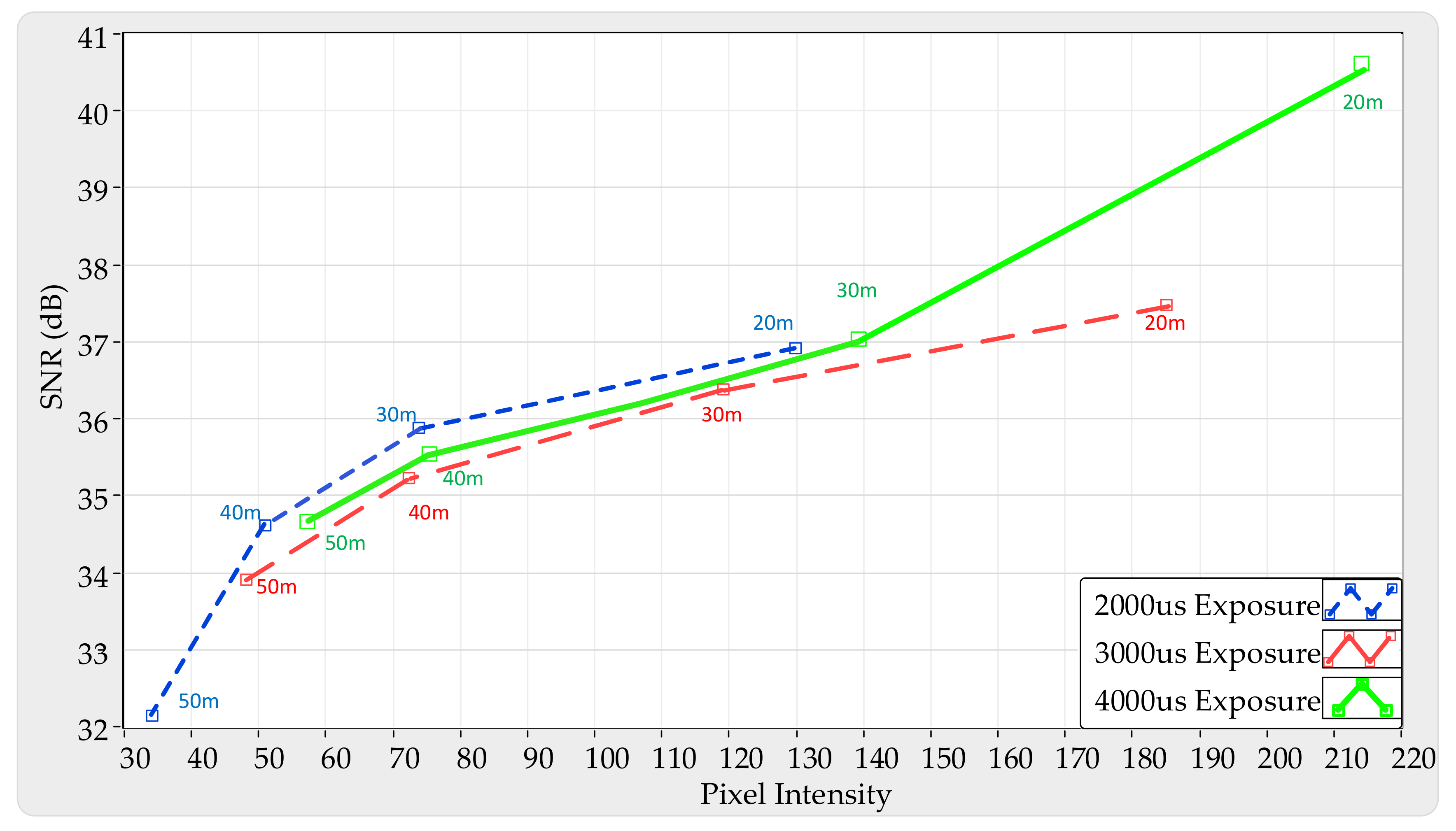
4.2. Experimental SNR Measurement
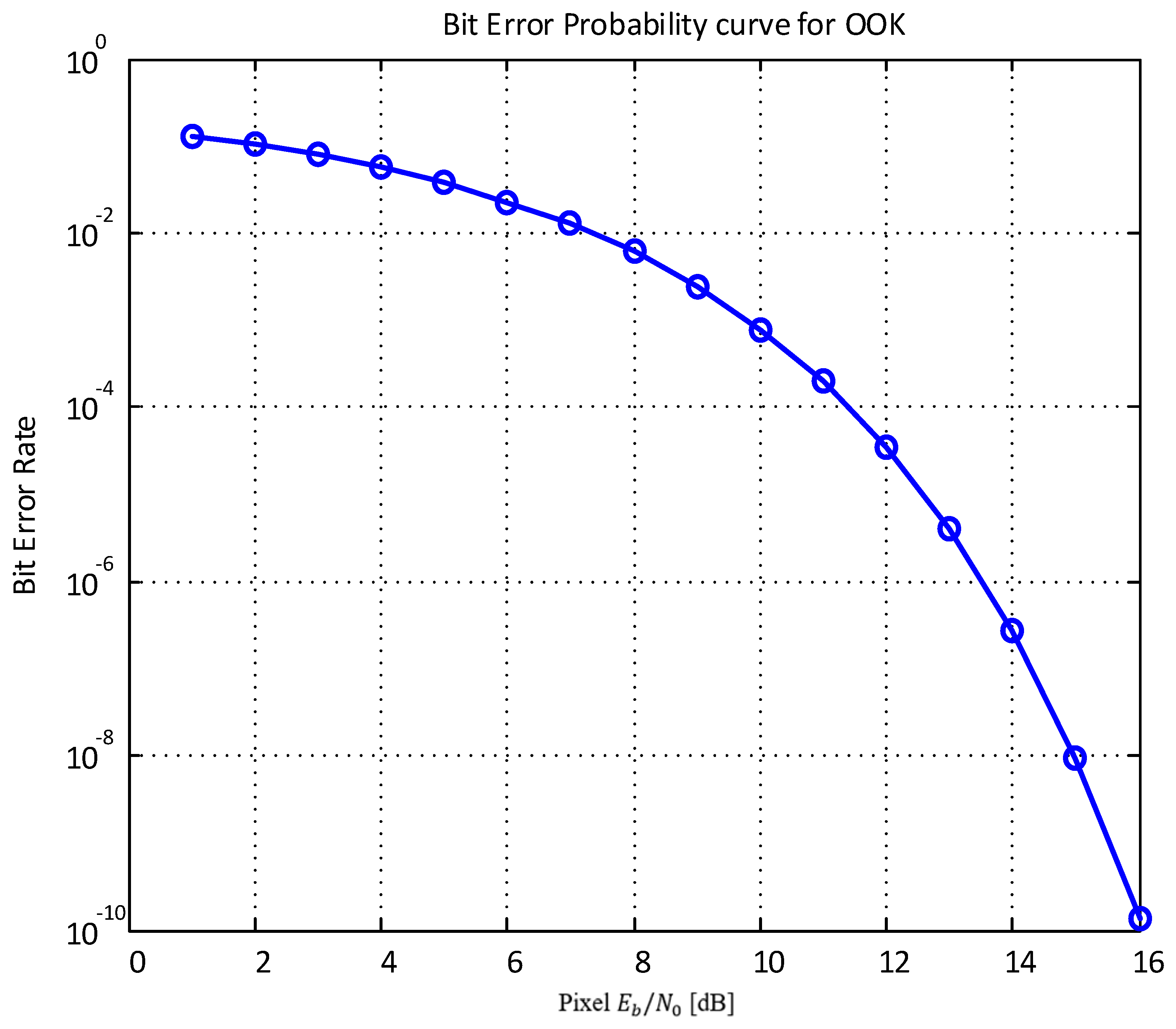
4.3. BER Estimation for Optical OOK Method
4.4. Proposed Scheme
4.4.1. Data Frame Structure
4.4.2. Detect Signal
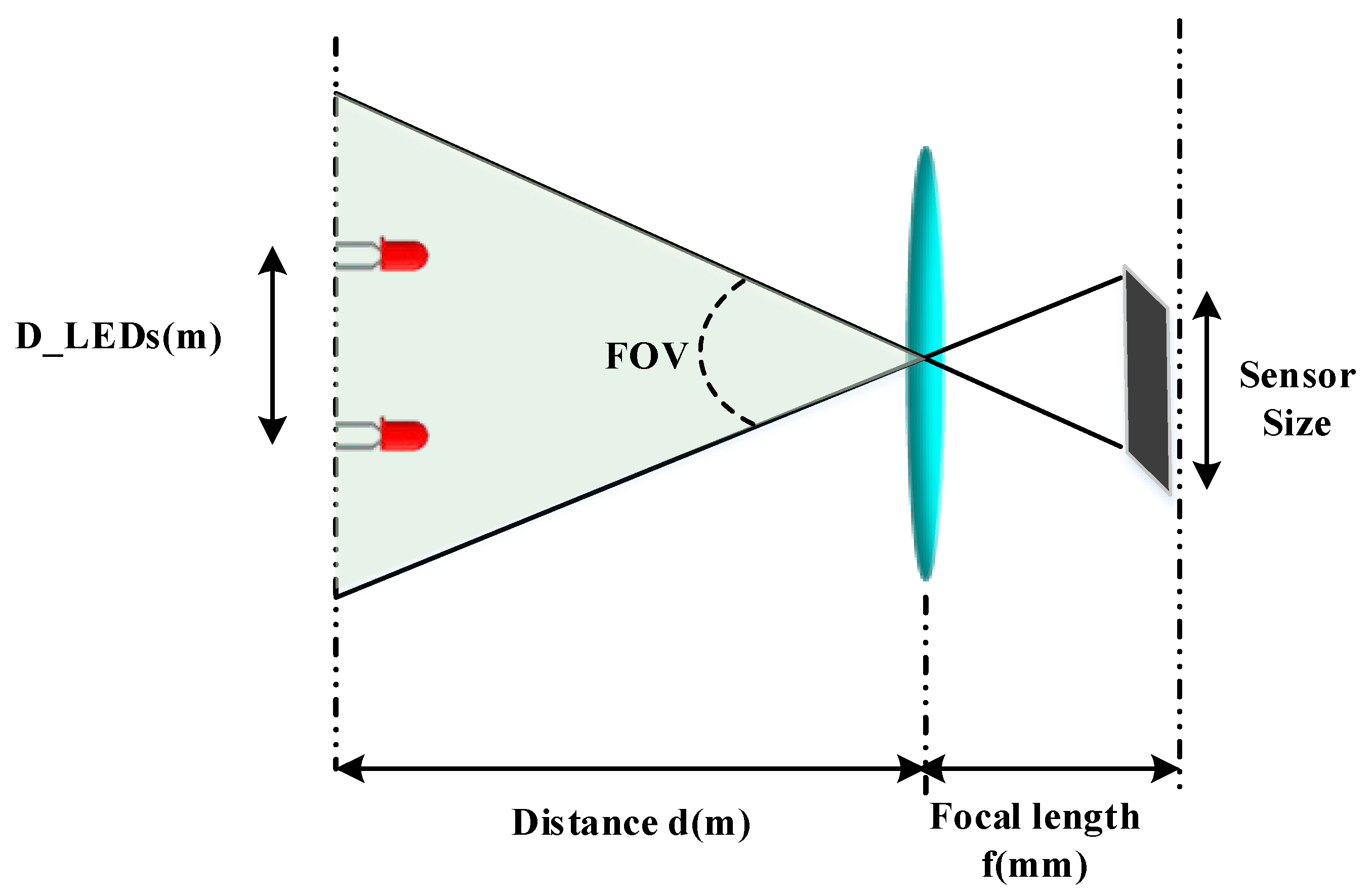
4.4.3. Minimum Distance Between Two LEDs
4.5. Implementation System Monitoring Using MIMO-OOK
5. Conclusions
Supplementary Materials
Author Contributions
Funding
Conflicts of Interest
References
- Elijah, O.; Rahman, T.A.; Orikumhi, I.; Leow, C.Y.; Hindia, M.N. An Overview of IoT and Data Analytics in Agriculture: Benefits and Challenges. IEEE Internet Things J. 2018, 5, 3758–3773. [Google Scholar] [CrossRef]
- IERC. European Research Cluster on the Internet of Things-Outlook of IoT Activities in Europe. March 2015. Available online: http://www.internet-of-things-research.eu/pdf/ (accessed on 20 September 2017).
- Kim, J.H.; Lee, J.K.; Kim, H.G.; Kim, K.B.; Kim, H.R. Possible Effects of Radiofrequency Electromagnetic Field Exposure on Central Nerve System. Biomol. Ther. 2019, 27, 265–275. [Google Scholar] [CrossRef] [PubMed]
- Rawat, B.S.; Aggarwal, B.; Passi, D. LI-FI: A New Era of Wireless Communication Data Sharing. Int. J. Sci. Technol. Res. 2014, 3, 113–124. [Google Scholar]
- Nikola, S.; Volker, J.; Min, J.Y.; John, L.Q. An Overview on High-Speed Optical Wireless/Light Communications 2017. Available online: https://mentor.ieee.org/802.11/dcn/17/11-17-0962-02-00lc-an-overview-on-high-speed-optical-wireless-light-communications.pdf (accessed on 25 November 2019).
- IEEE-SA. IEEE Std 802.15.7-2011-IEEE Standard for Local and Metropolitan Area Networks-Part 15.7: Short-Range Wireless Optical Communication Using Visible Light; IEEE-SA: Piscataway, NJ, USA, 2011. [Google Scholar]
- Nagura, T.; Yamazato, T.; Katayama, M.; Yendo, T.; Fujii, T.; Okada, H. Improved decoding methods of visible light communication system for its using LED array and high-speed camera. In Proceedings of the IEEE 71st Vehicular Technology Conferences (VTC), Taipei, Taiwan, 16–19 May 2010; pp. 1–5. [Google Scholar]
- Pathak, P.H.; Feng, X.; Hu, P.; Mohapatra, P. Visible light communication, networking, and sensing: A survey, potential and challenges. IEEE Commun. Surveys Tuts. 2015, 17, 2047–2077. [Google Scholar] [CrossRef]
- Ott, C.; Eiberger, O.; Friedl, W.; Bauml, B.; Hillenbrand, U.; Borst, C.; Albu-Schaffer, A.; Brunner, B.; Hirschmuller, H.; Kielhofer, S.; et al. A humanoid two-arm system for dexterous manipulation. In Proceedings of the IEEE-RAS International Conferences Humanoid Robot, Genova, Italy, 4–6 December 2006; pp. 276–283. [Google Scholar]
- Tan, K.S.; Hinberg, I.; Wadhwani, J. Electromagnetic interference in medical devices: Health Canada’s past current perspectives and activities. In Proceedings of the IEEE International Symposium Electromagnetic Compatibility, Montreal, QC, Canada, 13–17 August 2001; pp. 1283–1284. [Google Scholar]
- Ong, Z.; Rachim, V.P.; Chung, W.Y. Novel Electromagnetic-Interference-Free Indoor Environment Monitoring System by Mobile Camera Image Sensor based VLC. IEEE Photonics J. 2017, 9, 1–11. [Google Scholar] [CrossRef]
- Haas, H.; Yin, L.; Wang, Y.; Chen, C. What is LiFi? J. Lightwave Technol. 2016, 34, 1533–1544. [Google Scholar] [CrossRef]
- Ali, A.Y.; Zhang, Z.; Zong, B. Pulse position and shape modulation for visible light communication system. In Proceedings of the International Conferences Electromagnetics Advanced Application, Palm Beach, FL, USA, 3–8 August 2014; pp. 546–549. [Google Scholar]
- Videv, S.; Haas, H. Practical space shift keying VLC system. In Proceedings of the IEEE Wireless Communication Networking Conferences, Istanbul, Turkey, 6–9 April 2014; pp. 405–409. [Google Scholar]
- Deng, P.; Kavehrad, M. Real-time software-defined single-carrier QAM MIMO visible light communication system. In Proceedings of the Integrated Communications Navigation Surveillance Conferences, Herndon, VA, USA, 19–21 April 2016; pp. 5A3-1–5A3-11. [Google Scholar]
- Cai, H.B.; Zhang, J.; Zhu, Y.J.; Zhang, J.K.; Yang, X. Optimal constellation design for Indoor MIMO visible light communications. IEEE Commun. Lett. 2016, 20, 264–267. [Google Scholar] [CrossRef]
- Nguyen, T.; Islam, A.; Hossan, T.; Jang, Y.M. Current Status and Performance Analysis of optical camera communication Technologies for 5G Networks. IEEE Access 2017, 5, 4574–4594. [Google Scholar] [CrossRef]
- Nguyen, T.; Islam, A.; Yamazato, T.; Jang, Y.M. Technical Issues on IEEE 802.15.7 m Image Sensor Communication Standardization. IEEE Commun. Mag. 2018, 56, 213–218. [Google Scholar] [CrossRef]
- Ayyash, M.; Elgala, H.; Khreishah, A.; Jungnickel, V.; Little, T.; Shao, S.; Rahaim, M.; Schulz, D.; Hilt, J.; Freund, R. Coexistence of WiFi and LiFi toward 5G: Concepts, Opportunities, and Challenges. IEEE Commun. Mag. 2016, 54, 64–71. [Google Scholar] [CrossRef]
- Nguyen, T.; Islam, A.; Jang, Y.M. Region of Interest Signaling Vehicular System using optical camera communication. IEEE Photonics J. 2017, 9, 1–20. [Google Scholar] [CrossRef]
- Nguyen, T.; Hossain, M.; Jang, Y. Design and Implementation of a Novel Compatible Encoding Scheme in the Time Domain for Image Sensor Communication. Sensors 2016, 16, 736. [Google Scholar] [CrossRef] [PubMed]
- Nguyen, T.; Thieu, M.D.; Jang, Y.M. 2D-OFDM for optical camera communication: Principle and Implementation. IEEE Access 2019, 7, 29405–29424. [Google Scholar] [CrossRef]
- Ong, Z.; Rachim, V.P.; Chung, W.-Y. Long range VLC Temperature Monitoring System using CMOS of Mobile Device Camera. IEEE Photonics J. 2017, 9, 1508–1509. [Google Scholar] [CrossRef]
- Lin, H.; Si, J.; Abousleman, G.P. Region-of-interest detection and its application to image segmentation and compression. In Proceedings of the 2007 International Conference on Integration of Knowledge Intensive Multi-Agent Systems, Waltham, MA, USA, 30 April–3 May 2007. [Google Scholar]
- Roberrts, R.D. Intel Proposal in IEEE 802.15.7r1. Available online: https://mentor.ieee.org/802.15/dcn/16/15-16-0006-01-007a-intel-occ-proposal.pdf (accessed on 25 November 2019).
- Bobby, B. Comparison the Performance of Free-Space Optical Communication with OOK and BPSK Modulation under Atmospheric Turbulence. Int. J. Eng. Sci. 2011, 3, 4391–4399. [Google Scholar]
- Popoola, W.O.; Ghassemlooy, Z.; Leitgeb, E. Free-space optical communication using subcarrier modulation in gamma-gamma atmospheric turbulence. In Proceedings of the 9th International Conference on Transparent Optical Networks (ICTON ’07), Rome, Italy, 1–5 July 2007; Volume 3, pp. 156–160. [Google Scholar]
- Nguyen, H.; Thieu, M.D.; Pham, T.L.; Nguyen, H.; Jang, Y.M. The Impact of Camera Parameters on Optical Camera Communication. In Proceedings of the 2019 International Conference on Artificial Intelligence in Information and Communication (ICAIIC), Okinawa, Japan, 11–13 February 2019. [Google Scholar]


| RLL Code | Proposed Preamble (SF) |
|---|---|
| Manchester | 011100 |
| 4B6B | 0011111000 |
| 8B10B | 0000111111111100000 |
| Transmitter Side | |||
| The number of LEDs | 1 | 2 | 3 |
| Clock rate | 20 Hz | ||
| LED type | 5V DC-0.2 W | ||
| Receiver Side | |||
| Camera type | PointGrey rolling shutter camera | ||
| Camera frame rate | 60 fps | ||
| Throughput | |||
| Bit rate | 20 bps | 40 bps | 60 bps |
© 2019 by the authors. Licensee MDPI, Basel, Switzerland. This article is an open access article distributed under the terms and conditions of the Creative Commons Attribution (CC BY) license (http://creativecommons.org/licenses/by/4.0/).
Share and Cite
Cong Hoan, N.; Van Hoa, N.; Thanh Luan, V.; Jang, Y.M. Design and Implementation of a Monitoring System Using Optical Camera Communication for a Smart Factory. Appl. Sci. 2019, 9, 5103. https://doi.org/10.3390/app9235103
Cong Hoan N, Van Hoa N, Thanh Luan V, Jang YM. Design and Implementation of a Monitoring System Using Optical Camera Communication for a Smart Factory. Applied Sciences. 2019; 9(23):5103. https://doi.org/10.3390/app9235103
Chicago/Turabian StyleCong Hoan, Nguyen, Nguyen Van Hoa, Vu Thanh Luan, and Yeong Min Jang. 2019. "Design and Implementation of a Monitoring System Using Optical Camera Communication for a Smart Factory" Applied Sciences 9, no. 23: 5103. https://doi.org/10.3390/app9235103
APA StyleCong Hoan, N., Van Hoa, N., Thanh Luan, V., & Jang, Y. M. (2019). Design and Implementation of a Monitoring System Using Optical Camera Communication for a Smart Factory. Applied Sciences, 9(23), 5103. https://doi.org/10.3390/app9235103