Article

Virtual Synchronous Generator Based on Hybrid Energy Storage System for PV Power Fluctuation Mitigation

Faculty of Engineering, King Mongkut’s Institute of Technology Ladkrabang, Bangkok 10520, Thailand
*
Author to whom correspondence should be addressed.
Appl. Sci. 2019, 9(23), 5099; https://doi.org/10.3390/app9235099
Submission received: 20 October 2019 / Revised: 20 November 2019 / Accepted: 21 November 2019 / Published: 25 November 2019
(This article belongs to the Special Issue Microgrids II)

Abstract

:
The application of renewable energy is stimulating since the environmental pollution and the increase in demand for global energy consumption have become the main concerns of humanity. However, the intermittent nature of renewable sources could seriously affect the frequency stability of the system which needs to be solved. In this paper, the Virtual Synchronous Generator (VSG) based on battery/supercapacitor Hybrid Energy Storage System (HESS) is proposed to handle the stochastic power output of Photovoltaic (PV). First, the power allocation methods for HESS and its comparison are illustrated. Second, the comparison of the frequency deviation suppression strategies is presented. Moreover, as the adjustable parameters of VSG (J, D) is a key superior to the conventional synchronous generator; hence, a part of this paper will be introduced a new evolutionary algorithm called Backtracking Search Optimize Algorithm (BSA) to tune the parameters of the VSG in real time. To investigate the control performance, the standalone microgrid is modeled in the MATLAB/Simulink environment. Several case studies are conducted, and the results prove the improvement of the system frequency by attenuating the maximum overshoot of frequency deviation from 50.18 Hz to 50.03 Hz.

1. Introduction

Electrical energy plays a major role in our life, and it is a key driver in the industrial society. The significant increase of global power consumption, the extinction of conventional energy resources such as coal, oil and gas, and the environmental pollution which is caused by the energy production, are the main challenge for the electric utility. To handle these issues, the application of renewable energy in form of microgrid can be considered as the best alternative energy resource. However, the application of distributed generators based on renewable sources can cause as many problems as it may be solved. The inherently intermittent and power fluctuation of the renewable sources such as Photovoltaic (PV) and wind turbines, and the variation of power demand are the significant factors of system stability degradation, especially when the microgrid is operated in islanded mode. Hence, a sophistication microgrid control is a must.
In a standalone microgrid, the entire consumption is fully supplied by the microgrid sources. The high penetration of renewable energy systems with its intermittent power output results in power supply-demand unbalancing and high-frequency variation. Therefore, to address these issues, the standalone microgrid highly relies on the Energy Storage System (ESS) which could function as energy buffer or backup to balance the system mismatch and to maintain the system frequency in a stipulate operation range [1]. The battery which is the most mature and the cheapest energy storage has been found in many applications such as frequency regulation by mitigating the impact of the PV and wind power fluctuation [2,3], power losses reduction in distribution grids [4], and peak shaving applications [5]. The lead-acid battery storage based on the traditional moving average algorithm was used to smooth the PV fluctuation in [6]. In [7], the author used the absorb/release ability of the Battery Energy Storage System (BESS) to compensate the high power fluctuation of PV. A low-pass filter was used in this paper to generate the power reference for BESS. The method was reported to have the capability of limiting PV power fluctuations. However, the usage of battery in the above application could seriously shorten the battery lifespan. To improve the lifespan of the battery by reducing the battery stress, the Hybrid Energy Storage System (HESS) was introduced [8,9]. Based on the characteristics of each energy storage system in Table 1 [10], the battery and supercapacitor are two different energy storages which have complemented characteristics. The combination of these energy storages are expected to relieve the battery charging/discharging stress, to improve the lifespan of the battery storage and to enhance the system efficiency.
In conventional power system, the synchronous generator plays a major rule as the electricity source. It could damp the effect of dynamic load transition and disturbance with the inherent droop control and inertia control. Hence, the system stability is maintained. Inspired by the synchronous generator dynamic behavior, an idea to add inertia artificially to the inverter-based generator has been emerged. The artificial inertia can be obtained by using energy storage-release/absorb characteristic together with the power electronic inverter/converter and the proper control mechanism in a system, so-called, Virtual Synchronous Generator (VSG). Since the VSG is expected to solve the major issues (low-inertia) in the microgrid, this relatively new scheme gains great attention and attracts many researchers from both universities and industries, and numerous scientific outcomes have been published recently [11,12,13,14]. Novel control for VSG based on algebraic with a minimal number of the parameter was introduced in [15] to suppress the fluctuation of frequency and voltage. As the designed parameters of the VSG is a challenging task, the authors [16,17,18] presented the method for tuning the parameters (J and D) of the VSG to improve the dynamic response of the system and to attenuate the frequency fluctuation. However, in those paper, the value of J and D are adapted based on the predefined criteria. The optimized method that could determine the optimum value of J and D is not investigated. In [19,20], the authors aim to improve the performance of the VSG that is simply implemented by the ideal DC voltage source connected to the inverter. All the control parts in the VSG such as inertia and speed governor, are realized by controlling the ideal DC voltage source which is obviously different from the VSG definition. In the real case, ESS is an inevitable part for the VSG to imitate the mechanical rotational energy of the synchronous generator. The VSG control strategy based on a HESS was presented in [21], but it does not take into account the continuously rapid changes in power demand or load transition. Therefore, it is difficult to evaluate the performance of the proposed VSG.
Although numerous VSG researches have been conducted to solve the challenging issue in the microgrid recently, the majority focuses on the improvement of the system stability. Hence, what remains unclear is how the VSG benefit when it deploys to mitigate the intermittent nature of PV and wind turbine. To tackle the frequency deviation which mainly results from the strong variation of PV output power as well as to bridge the gap in the literature, in this paper, the VSG based on battery/supercapacitor hybrid energy storage system is proposed. The supercapacitor is responsible for the high-frequency power variation while the battery corresponds to the low-frequency power variation. The novelty of this study introduces the new power allocation method for HESS and its combination with the adaptive VSG algorithm based on BSA to improve the frequency deviation suppression capability. The remaining part of the article organizes as follows. In Section 2, the method for power allocation of HESS is presented. The VSG control and the parameter tuning based on BSA are described in Section 3. The results and discussion are demonstrated in Section 4. The paper is concluded in Section 5.

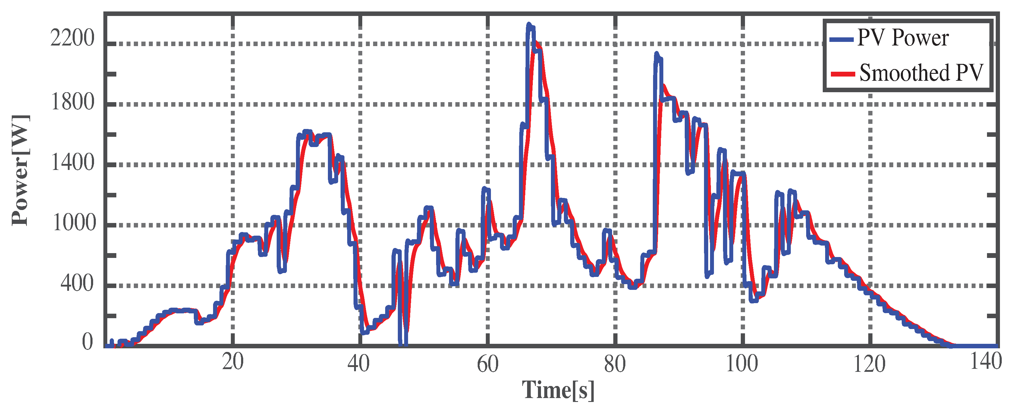
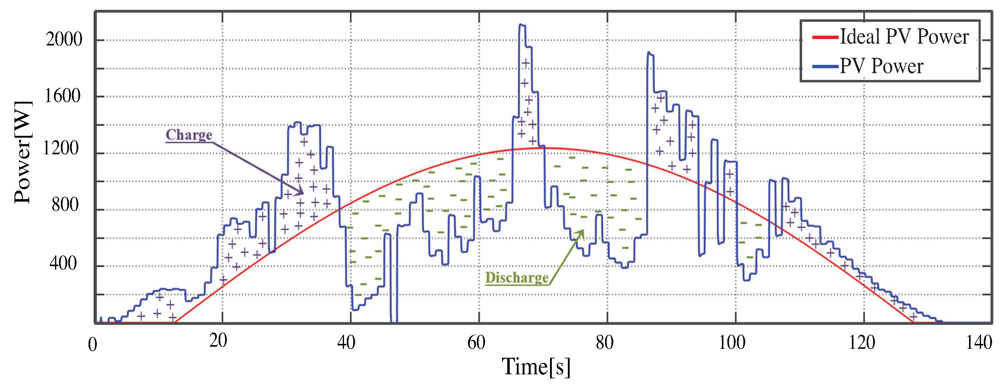
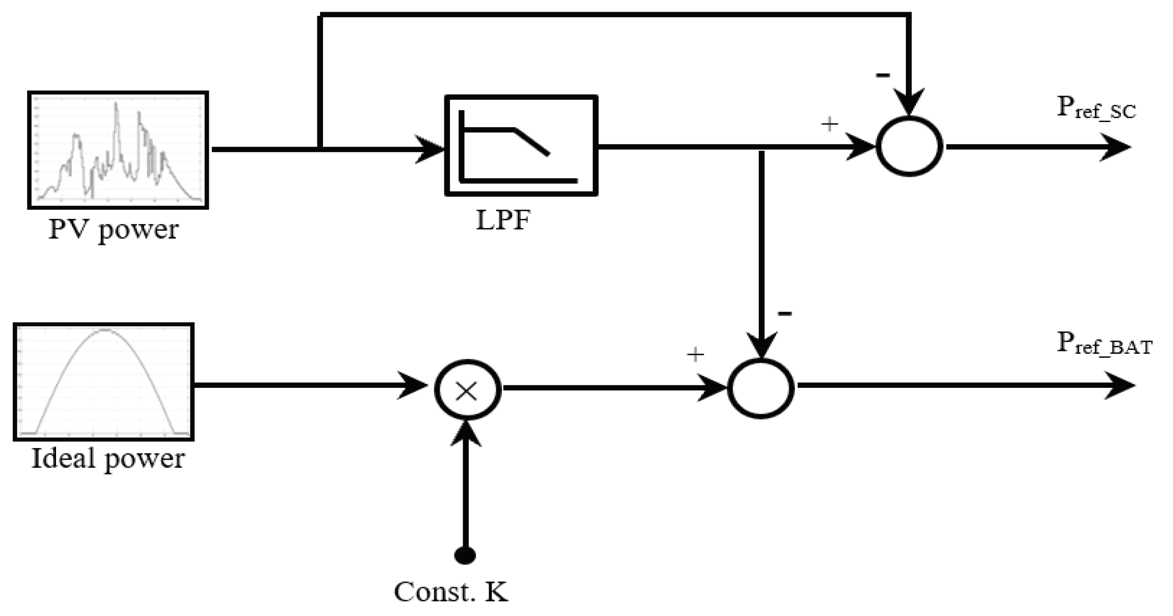
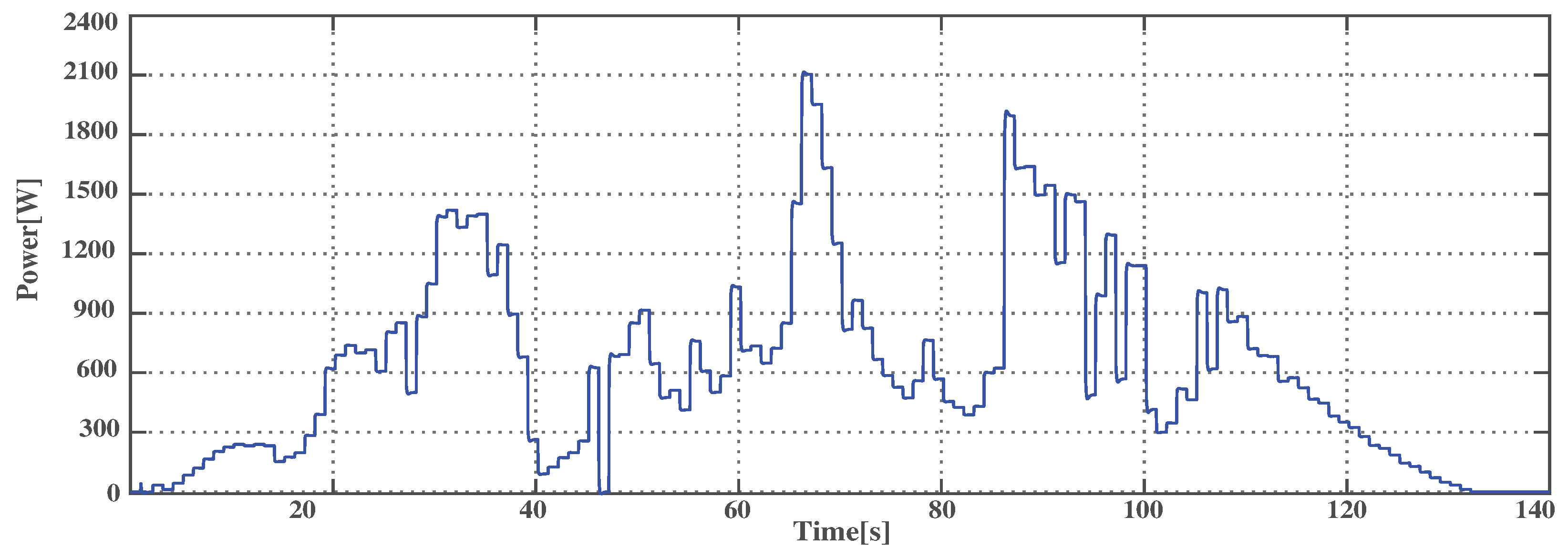
2. Power Allocation and Control for HESS

In this research, the complementarity of the two types of ESS (battery & supercapacitor) is to utilize the distinct advantages of multiple heterogeneous energy storage technologies and to hide their drawbacks instead of relying on a single type of energy storage technology. The applications of the battery with high energy capacity are in long-term and large-volume energy storage that requires high energy density, and sustained charge/discharge. The applications of the supercapacitor which has high power capacity are in periodic high-power output and frequently charge/discharge that require high power density, short response time, and long lifespan. Two methods, to allocate the power between battery and supercapacitor, are discussed in this section. The first method, called Method#1, was introduced by Hazra et al. [22] and the second method, also known as Method#2, is proposed by the author. In Method#1, two low-pass filters are used to separate the power for battery and supercapacitor as shown in Figure 1. Figure 2 is the smoothed power waveform based on Methode#1.
The power reference for supercapacitor ( P s c _ r e f ) and battery ( P b a t _ r e f ) are obtained through Equation (1).
P s c _ r e f = P p v P p v 1 τ 1 s + 1 P b a t _ r e f = P p v 1 τ 1 s + 1 P p v 1 τ 2 s + 1
where, τ 1 and τ 2 are the time constant of low-pass filter #1 and low-pass filter #2, respectively. P p v is the measured power output of the PV.
However, in [22], the method to design cut-off frequency for the low-pass filter is not provided. In [23], the same method to allocate the power for HESS is applied, the cut-off frequency is selected based on the response time of each energy storage system. Therefore, according to [23], the cut-off frequency f c 1 = 0.5 Hz and f c 2 = 1 mHz are chosen for L P F # 1 and L P F # 2 , respectively.
The Method#2 is inspired by [24]. Instead of using ramp rate and step moving average, an ideal PV power profile is used. The ideal PV power is obtained by comparing the daily PV output power during one year, and selected the one which has smaller variation. The idea behind this method is to inject the smooth power to the system with supporting from ESS. Hence, the impact of intermittent PV output power is diminished. As shown in Figure 3, the ESS is used to compensate the power deviation of PV. When the PV output power is greater than the ideal power, the ESS will absorb; otherwise, the ESS will release the power to compensate. As a result, the power supply from the PV plus energy storage system are similarly to the ideal power as demonstrated in Figure 3 ( r e d g r a p h ). The block diagram of this method is shown in Figure 4. This method, a low-pass filter ( f c = 0.5 Hz) and an ideal power are used to allocate the power for HESS. The power reference for supercapacitor and battery are expressed by Equation (2).
P s c _ r e f = P p v P p v 1 τ 1 s + 1 P b a t _ r e f = P p v 1 τ 1 s + 1 K P i d e a l
where P P V is the measured power output of PV and τ is the time constant of low-pass filter. P i d e a l is the ideal output power of PV. K is the constant to determine amplitude of ideal PV output power which is in range [0,1]. In case, there is PV power prediction included, the constant K is obtained from dividing the average of prediction power by the average ideal power ( K = P ¯ p r e d i c P ¯ i d e a l ). The PV power prediction and the method to determine the value of the constant K will be detailed in next research. In this paper, the constant K is pre-selected (K = 0.5).

Methods Comparison

The performance of power allocation methods are compared based on the ability to suppress the frequency deviation. In this section, the synchronous d q reference control is used, and its control block diagram is illustrated in Figure 5. The measured power output of P V is injected into power allocation block (Method#1 and Method#2) to generate the reference active power for battery and supercapacitor. To perform the d q decoupling control, measured inverter output voltage and current which is in natural frame ( a b c ) needs to transform into synchronous reference frame ( d q ) first. The single-phase transformation from natural frame ( a b c ) to stationary frame ( α β ) is provided in Equation (3) that V α is in phase with V a , and V β is obtained by shifted V a in 90 (lagging). Then, the stationary frame to the synchronous frame is expressed in Equation (4). The inner current control loop controls the current supplied by the converter to match its desired value by comparing the desired current value ( I = P V ) with the measured current I d . The modulating signals ( m d and m q ) which use to control the switching time of I G B T can be obtained via the Equation (5).
v α v β = v a v a ( ω t π / 2 )
v d v q = c o s ( θ ) s i n ( θ ) s i n ( θ ) c o s ( θ ) v α v β
m d = V d I q ω L + k p ( I d I d ) + k i ( I d I d ) m q = V q + I d ω L + k p ( i q I q ) + k i ( I d I q )
In Formular (5), V d , V q , I d and I q are voltage and current in d q component. k P , k i are proportional and integrator gain of P I controller. L is line inductance and ω is rated angular frequency.
To assess the effectiveness of each power allocation methods; a strong PV power fluctuation profile is utilized as shown in Figure 6. Figure 7 is the frequency response based on each power allocation methods. There are three waveforms in this figure. The b l a c k g r a p h represents frequency of the system without energy storage system. The b l u e g r a p h is frequency response based on Method#1, and the r e d g r a p h is based on the proposed method (Method#2). By observing the Figure 7 during the time t = 63 s to t = 68 s, it is clear that the frequency deviation mitigation based on Method#1 has higher variation overshoot compare to its counterpart Method#2 with frequency deviation overshoot 50.4 Hz and 50.1 Hz, respectively. Therefore, the proposed method (Method#2) is selected to allocate the power for HESS in this research.

3. Frequency Deviation Suppression Based on VSG

Due to the extraordinary increase in global energy consumption and environmental pollution, the application of renewable energy based on inverter is dramatically increased. However, the inertia-less of these inverter-based generators could degrade the system stability and quality. To handle these issues, the idea is emerged by adding virtually inertia to the inverter-based distributed generator which so-called virtual synchronous generator. The following section will be discussed about the model and control of VSG.

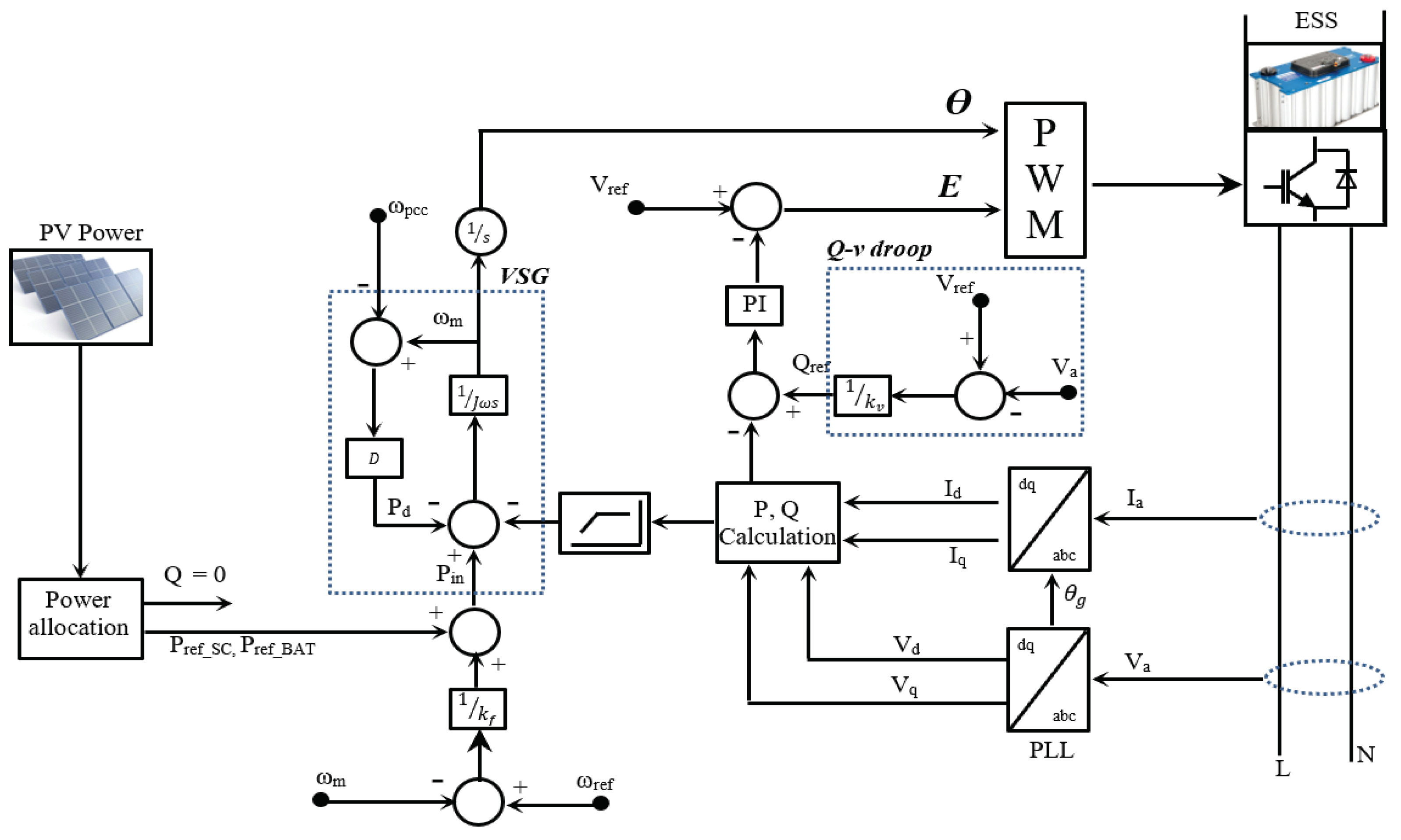
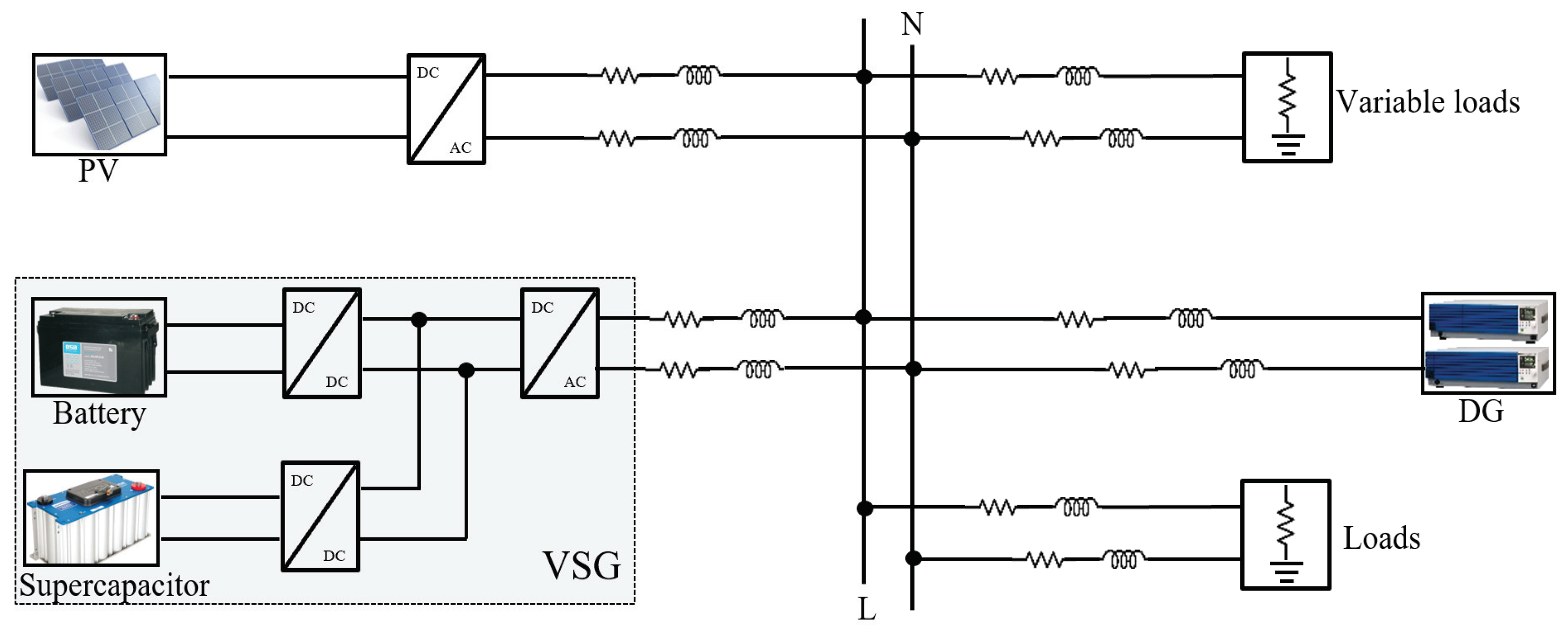
3.1. VSG Model and Control

The VSG is formed by three important elements such as energy storage system, inverter, and a proper control algorithm. By taking the benefit of release/absorb characteristic of ESS, a proper designed control scheme could control the inverter to mimic the dynamic behavior of the synchronous generator. The VSG algorithm is implemented based on the swing equation of a synchronous generator and it is given in Equation (6).
J d ω m d t = T m T e
where T m , T e is the generator’s mechanic torque and electromagnetic torque, respectively. J is a moment of inertia, and ω m is generator’s angular frequency.
By multiplying the Equation (6) with angular frequency ( ω m ), the swing equation in term of power ( P = ω m . T ) is obtained as express in Equation (7).
J ω m d ω m d t = P m P e
The P ω and Q v droop control are commonly used in the primary frequency and voltage regulation. The relation between P ω and Q v are given in Equation (8).
ω m = ω r e f k f ( P m P r e f ) V a = V r e f k v ( Q m Q r e f )
Moreover, in order to fully mimic the conventional synchronous generator, the damping term ( D ( ω m ω p c c ) ) due to damper winding, mechanical friction and electrical losses are commonly added to swing equation. By substituting the damping term and frequency governor model (Equation (8)) into Equation (7), the swing equation for the VSG in this research is obtained as expressed in Equation (9).
J ω m d ω m d t = P r e f ω m ω r e f k f P o u t D ( ω m ω p c c )
In Formula (9), P o u t is the measured power output of VSG which is equivalent to P e . ω m is the VSG’s angular frequency and ω p c c is the angular frequency at the point of common coupling. J and D are the virtual inertia and damping factor, respectively. Designing the VSG parameters such as J and D are the challenging task. For the sake of simplicity, the parameter J and D [25] could be calculated based on Equation (10) which follows the synchronous generator.
J = 2 H S n ω 2 D = Δ S ω Δ ω
where H is the inertia constant, which is in range [2 s–10 s]. S n is the base power of generator, ω is the angular frequency which equals to 2 π f and Δ ω ( Δ ω = ω m ω p c c ) is the allowable deviation frequency which equals to 2 π . To understand the effect of virtual inertia and damping factor on the system’s frequency, the Equation (9) is derived as.
d ω m d t = P r e f ω m ω m ω r e f k f ω m P o u t ω m D ( ω m ω p c c ) ω m J
Δ ω = P r e f ω m ω r e f k f P o u t J ω m d ω m d t D
In Equation (11), assuming that ( P r e f ω m ω m ω r e f k f ω m P o u t ω m D ( ω m ω p c c ) ω m ) is constant. If the value of J is increased, the d ω m d t will be decreased. Similarly, in Equation (12), assuming that ( P r e f ω m ω r e f k f P o u t J ω m d ω m d t ) is constant. If the parameter D gets bigger, Δ ω will become smaller. Hence, the large value of J and D result in a small frequency deviation; at the same time, they maximize the power, generated or absorbed by the energy storage system. However, there is a side-effect for larger value selection of parameter J and D such as causing overload the inverter, increasing the settling time, requiring the high accuracy of P L L . Therefore, the optimum value selection of J and D could significantly ensure the system stability.
The overall control block diagram of VSG is provided in Figure 8. The reference power is obtained from the power allocation Method#2.
The P , Q calculation block computes the power output of the VSG via the Formula (13).
P o u t = 1 2 ( 1 τ s + 1 ) ( V d I d + V q I q ) Q o u t = 1 2 ( 1 τ s + 1 ) ( V q I d V d I q )
where V d , V q , I d , I q are d q a x i s output voltage and current, respectively. A low-pass filter with cut-off frequency, f c = 0.6366 Hz, is added to the measured power to diminish the noise from measurement device. From the VSG and Q v droop control block, the virtual phase angle ( θ m ) and the voltage amplitude (E) are obtained, respectively. The multiplication of voltage amplitude (E) with the phase angle s i n ( θ m ) generates the sinusoidal P W M to control the switching time of inverter.

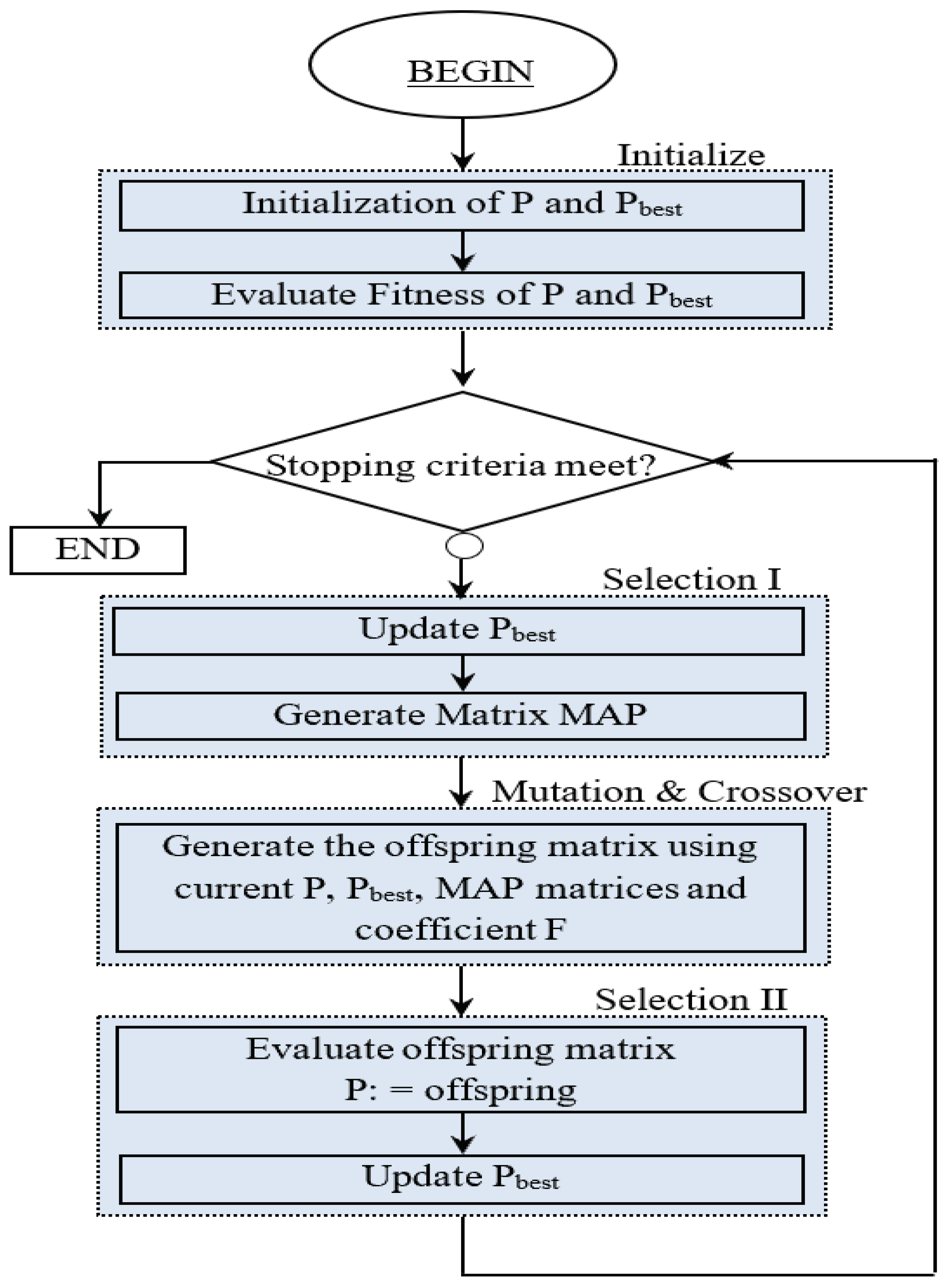
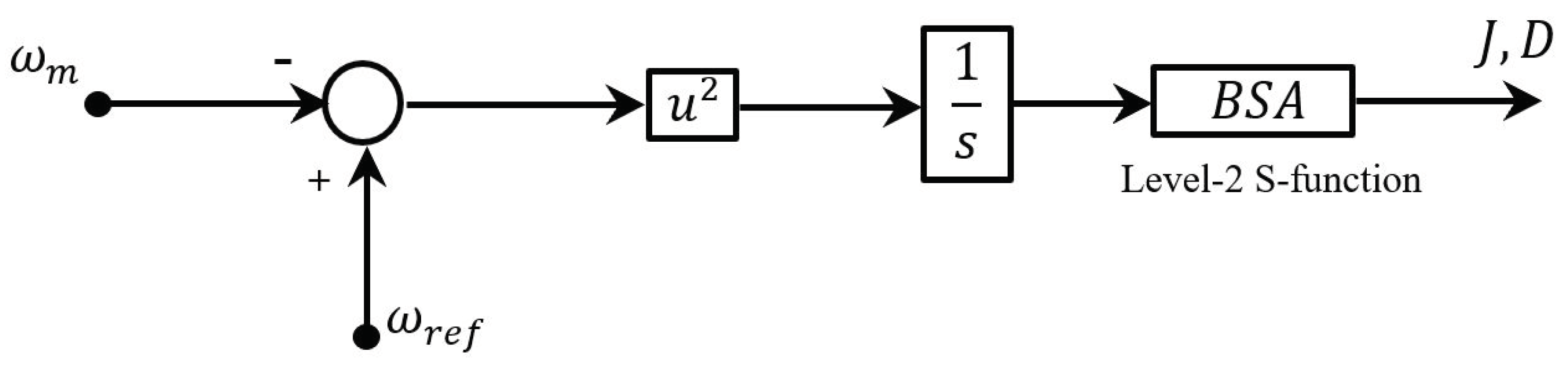
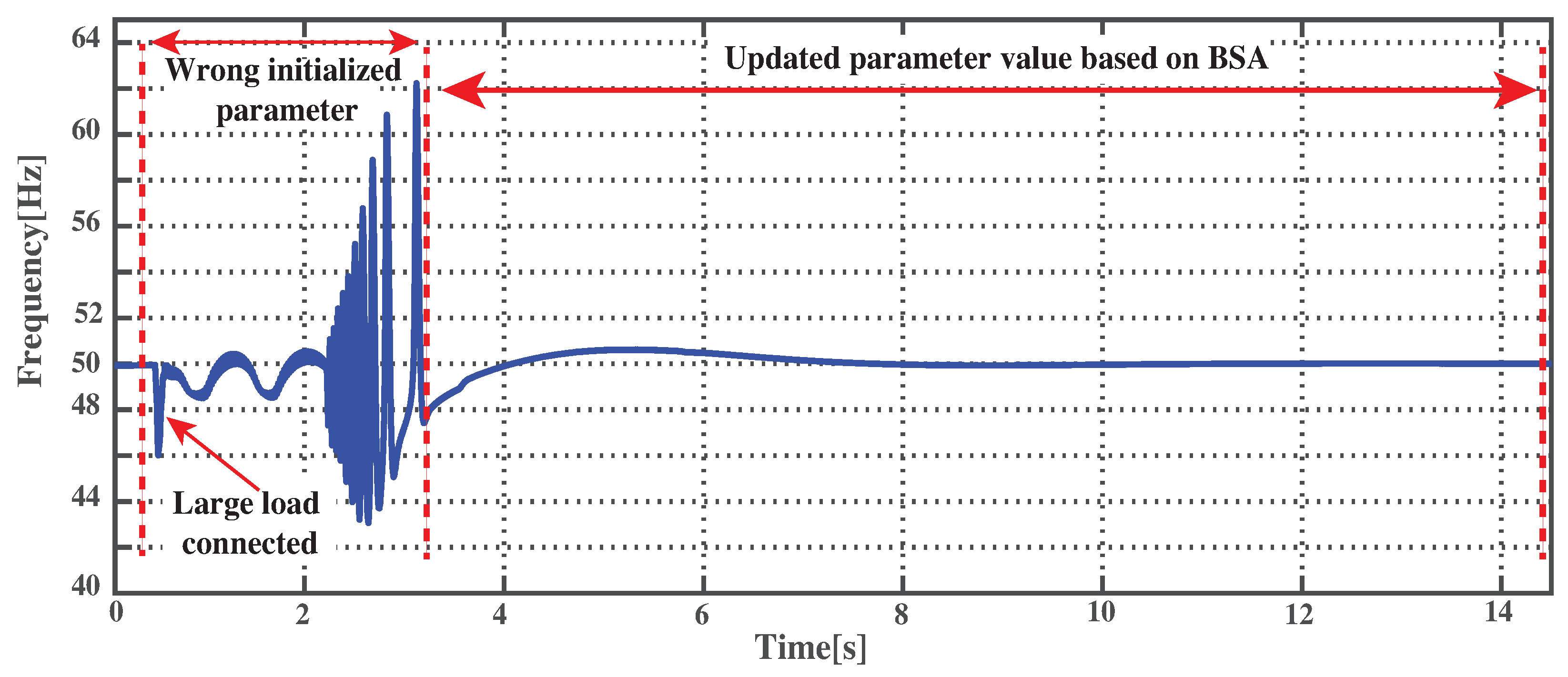
3.2. Tuning VSG Parameter Based on BSA

Optimization is a powerful tool which is used by the researchers in various applications over the past few decades in purpose to extract maximum benefits from the system by finding the best values of system parameters through the maximization or minimization of the objective function. As discussed in Section 3.1, the VSG emulates the SG’s dynamic characteristic by representing the SG fundamental swing equation to create the virtual inertia and damping factor. Unlike a real synchronous machine, the parameters of VSG can be tuned to improve the dynamic response of the system. In this research, a new evolutionary optimization called BSA is used for online tuning the parameters (J and D) of VSG.
The objective function:
I S E = T s t a r t T s t o p ( ω r e f ω m ) 2
The design problem can be formulated by minimizing I S E (Equation (14)) in order to determine the optimum values of J and D. A brief discussion on BSA is provided below.
BSA [26] is a new population-based evolutionary algorithms. It tries to minimize the objective function by performing the iterative process. Five evolutionary mechanisms such as i n i t i a l i z a t i o n , s e l e c t i o n I , m u t a t i o n , c r o s s o v e r , and s e l e c t i o n I I employed in BSA. The complete process of BSA provides in Figure 9.
- Initialization: The population P = ( P i , j ) ( N , M ) and o l d P i , j are initialized via a uniform stochastic selection of particles values within the solution space, as shown by Formula (15). The fitness function is first evaluated by using the initialized value of the population.
P i j = P j m i n + r n d ( P j m a x P j m i n ) ; ( Initialization of population , P . ) o l d P i , j = P j m i n + r n d ( P j m a x P j m i n ) ; ( Initialization of oldP . ) f i t n e s s P i , j = o b j F u n ( P i ) ; ( Initial fitness value P . )
where ( i ) { 1 , , N } , ( j ) { 1 , . , M } . N is the number of population and M is the number of dimensions. The dimensions is referred to the number of variable that needs to define(J and D).
- S e l e c t i o n I : There are three things done in S e l e c t i o n I such as update P b e s t matrix, memorize the previous experience ( o l d P ) and random order based on Equation (16), and generate binary integer-valued matrix ( m a p ).
o l d P i j = p e r m u t i n g ( o l d P ) .
- M u t a t i o n : The trial population Mutant is initialized in the Mutation step by following the Equation (17).
m u t a n t i j = P i j + F ( P b e s t i j P i j ) ( i ) { 1 , , N } ; ( j ) { 1 , . , M }
where F is the real number to control the step size of search path or direction.
- C r o s s o v e r : Generates the final form of the trial population ( o f f s p r i n g ).
- S e l e c t i o n I I checks whether fitness o f f s p r i n g s gives better fitness value than that obtained so far using initial population or not. If fitness o f f s p r i n g s gives better results, then update offsprings by fitness offsprings via P b e s t matrix; otherwise, keep the previous one. Keep doing the same process until termination criterion is met.
Figure 10 demonstrates the interface between the simulation model and the optimization algorithm ( B S A ). The B S A embeds in the simulink environment using the Level2 S-function. The parameter J and D are set as the tunable parameter. Figure 11 shown a testing case result to observe whether the parameter is properly online tuned. At the time of simulation start, the value of J and D are intentionally wrong initialized. As shown in Figure 11, at time t = 0.5 s, the large loads are connected and the system is unstable as the virtual inertia and damping constant are wrong initialized. Hence, the oscillation cannot be damped during that period. To update the VSG parameter which generates by BSA, it requires to enable update mode from Simulation menu ( S i m u l a t i o n U p d a t e D i a g r a m ). One the update diagram is clicked; the VSG parameters are kept updating based on B S A and the system becomes stable as seen in Figure 11 from t = 3 s to the end of the simulation.

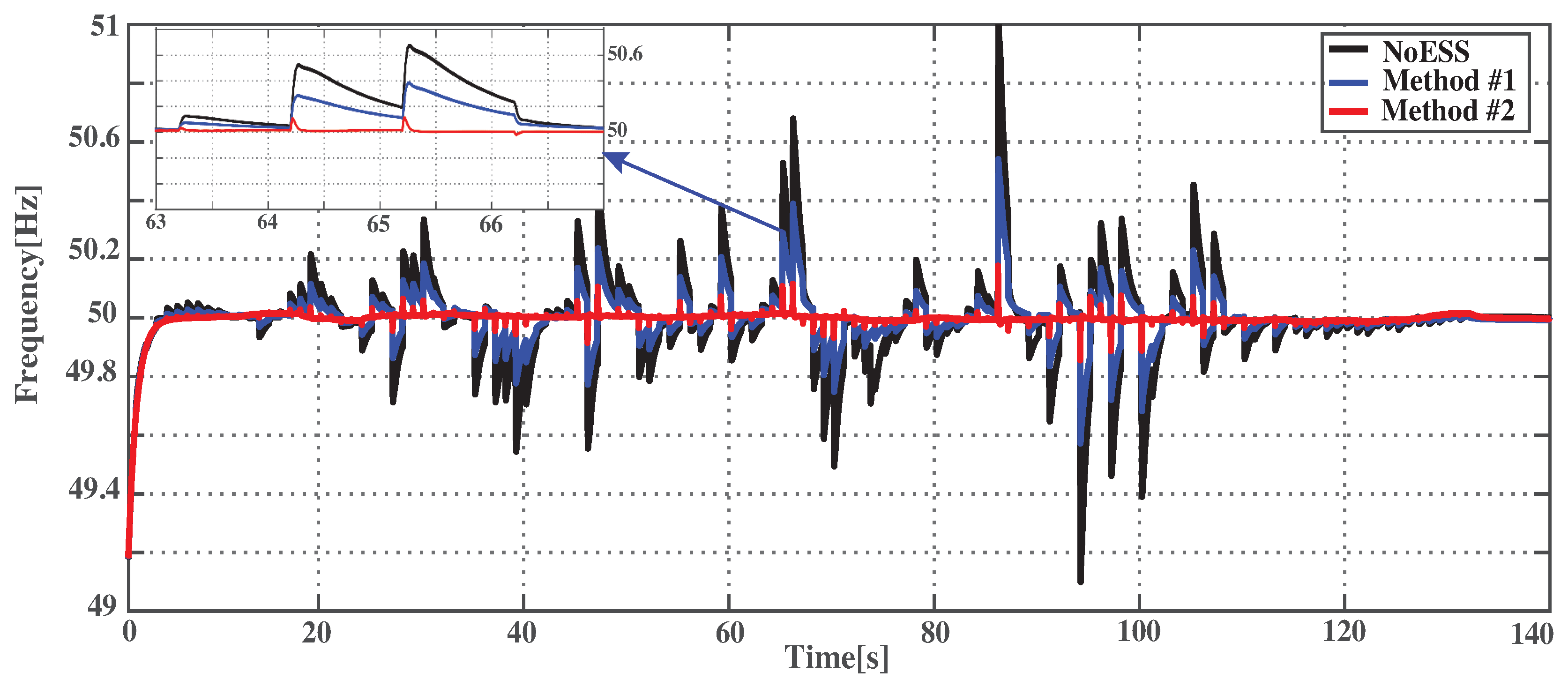
4. Simulation Results and Discussion

In this research, a standalone microgrid is implemented under MATLAB/Simulink platform as shown in Figure 12. The equipment such as power supply, battery, PV simulator, etc., are modeled based on the real equipment which is available in the laboratory for later experimental purpose. The important parameters are provided in Table 2. It is worth mentioning that the objective of this simulation is to demonstrate the ability of VSG to mitigate the frequency deviation which results from the strong variation of PV output power. Hence, the reactive power control will not be focused in this study. Several case studies are carried out and discussed below.

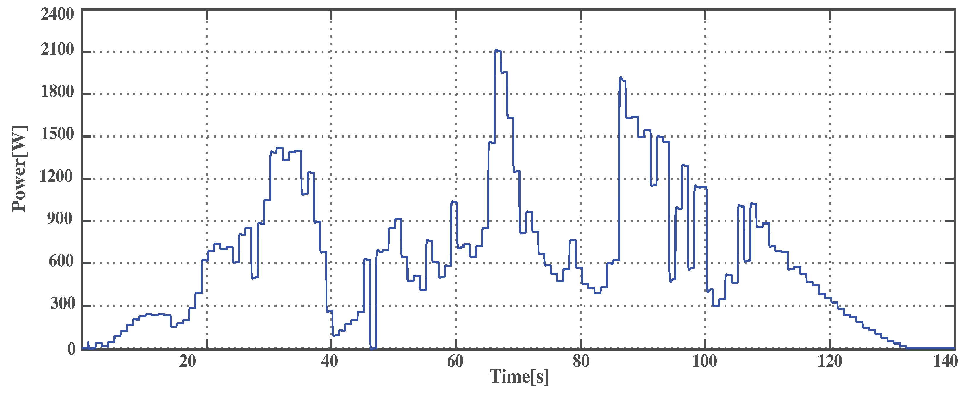
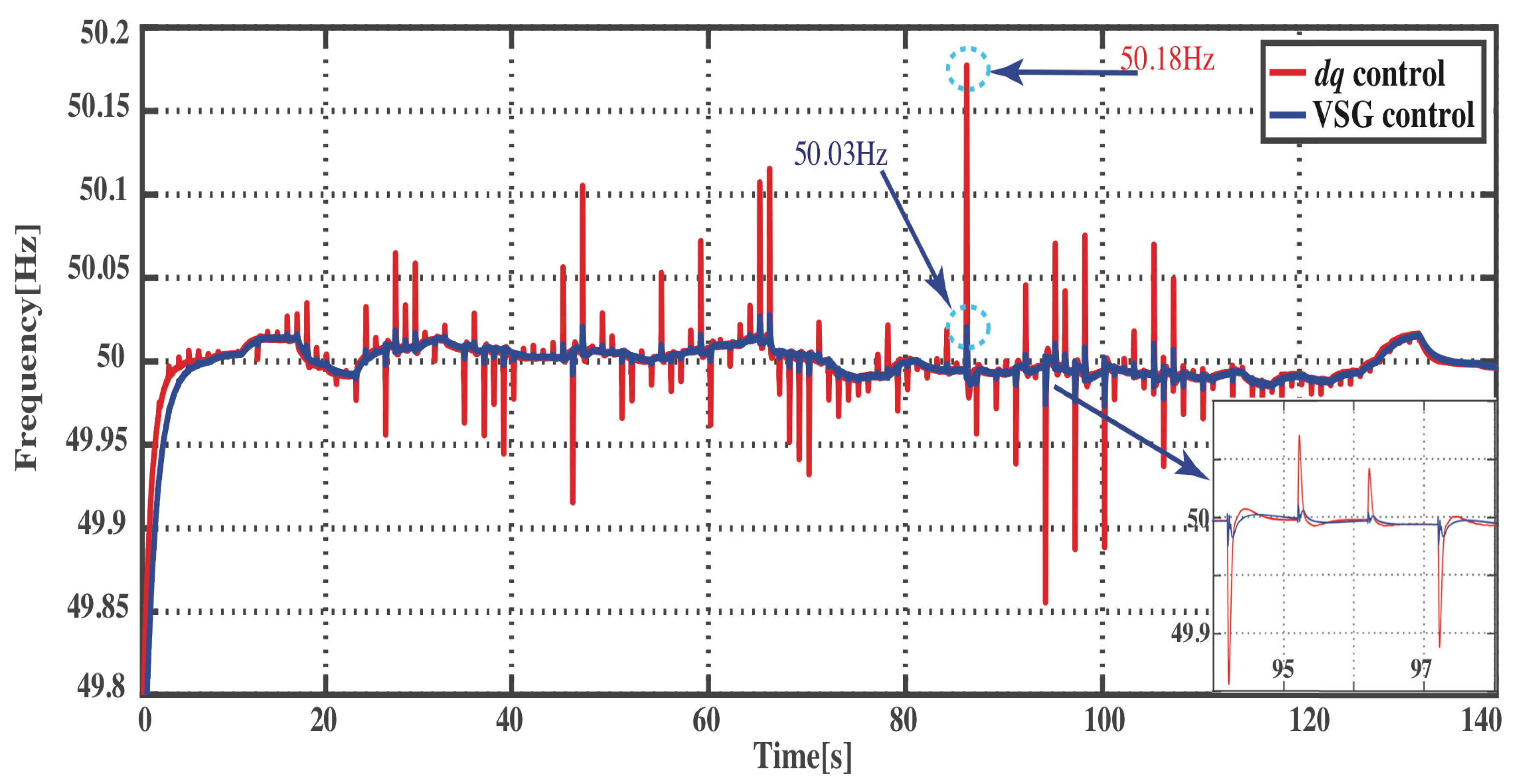
4.1. PV Power Variation

This scenario aims to investigate the performance of VSG control combining with the proposed power allocation Method#2 to suppress the frequency deviation which results from stochastic power output of PV. A worth case PV profile which is recorded on 24 January 2015 from laboratory Rooftop-PV ( P 2.1 kW) is used as illustrated in Figure 13. Five minutes data in the real-time is scaled to 1 s in the simulation environment via Rate Transition Simulink Block.
Figure 14 presents the frequency response of the VSG control and the current d q d e c o u p l i n g control based on Method#2. This result is obtained when it takes into account the strong variation power output of PV. According to this waveform, it is obvious that the VSG ( b l u e g r a p h ) could suppress the oscillation frequency more effectively than the normal d q d e c o u p l i n g control ( r e d g r a p h ) by using the same amount of power from HESS. The power and S o C of the HESS are provided in Figure 15. In Figure 15a, the b l u e g r a p h represents the power of supercapacitor and r e d g r a p h is the power of battery. Since the supercapacitor is responsible for high power variation, its power and S o C (Figure 15b) are strongly fluctuated. Meanwhile, the battery’s power and S o C (Figure 15c) are smoothly changed. As a result, the battery lifespan is expected to be improved due to low stress.

4.2. Load Transient

In this case, the simulation time is reduced from 140 s to 20 s. To observe the performance of VSG during the load transition, a group of load with the power consumption, 1.5 kW (25%), is connected into the system at the time t = 3 s with the initial consumption 4.2 kW, and disconnected around 45% at the time t = 10 s as shown in Figure 16. The VSG here will be compared with the modified droop control [27]. In Figure 17, b l u e g r a p h is the frequency response of the VSG, and r e d g r a p h is the frequency response of the modified droop control. It is clearly seen that the VSG which emulates the synchronous generator dynamic characteristic could provide the inertia and damping support to the system, as a result, it has smaller frequency overshoot/undershoot compare to the modified droop control when there is a sudden increase in power demand.

4.3. Comparison between Constant and Tuning Parameters of VSG

As mentioned in Section 3.2, adapting the parameters (J,D) of VSG is the key superior to the conventional synchronous generator to enhance the system dynamical response. Therefore, an online adapting based on BSA is investigated in this section. It is worth to mention that the increase in number of population and epoch could provide the better result by reducing the overshoot and settling time; at the same time, it increases the computation burden and simulation time. The parameter of BSA such as population size and epoch are set to 25 and 5, respectively, by considering the trade-off between computation burden and performance. The virtual inertia (J) and damping factor (D) which are computed by BSA is shown in Figure 18. To investigate the perfomance of adapting VSG’s parameters, two case studies as discussed in Section 4.1 and Section 4.2 are conducted.

4.3.1. PV Power Variation

The PV power in Figure 13 is used to realize the high PV power variation. The result of the frequency response with the online updating parameter is compared to the VSG constant parameters. Figure 19 is the system frequency response of the adaptive parameter by BSA and the constant parameter. It shows that with the tuning parameter, the system has smaller frequency overshoot compared to the constant parameter. Although the improvement is small, it proves the promising performance of the adaptive parameter.

4.3.2. Load Transient

In this case, the load transient is applied to the system supplementary with the high fluctuation PV power. The power demand waveform is shown in Figure 20. To create the load transient event, 45 percent of total power demand is connected and disconnected at time t = 5 s and t = 12 s, respectively. Three control schemes such as modified droop control, constant VSG parameter and adapted VSG parameter are compared. The frequency response of the system demonstrates in Figure 21. By observing at the time t = 5 s and t = 12 s, the system operates in unacceptable frequency range when the system is equipped with the modified droop control ( c y a n g r a p h ). In case, the constant VSG parameter is applied, the system has a relative large deviation. But, it is still in acceptable frequency range ±0.5 Hz ( b l u e g r a p h ). While the adaptive parameter ( r e d g r a p h ) is adopted, the frequency deviation overshoot is efficiently suppressed which is in range ±0.2 Hz. This witness that the online tuning method could reduce the frequency deviation more effectively compared to other two control schemes.

5. Conclusions

In a standalone microgrid, the intermittent nature of renewable energy and the load transition are the main factors of the system stability degradation. In this paper, a new control theme called VSG has been introduced to suppress the amplitude of the frequency deviation which results from the fluctuation power output of the PV. The VSG is implemented based on supercapacitor/battery hybrid energy storage system. Considering, the tunable of VSG parameters, an optimization method, BSA, is utilized for online tuning the inertia and damping factor of VSG. To investigate the performance of the proposed control, the standalone microgrid is implemented in MATLAB/Simulink. Two scenarios such as strong variation power and the load increase are conducted, and the comparison studies on the control performance of the dq-decoupling control versus proposed VSG control, the VSG control versus modified droop control, and the constant VSG versus adapting VSG control was presented. The simulation results prove the effectiveness of the proposed method to suppress the overshoot of frequency deviation which results from the intermittent power of PV and the load transient from 50.18 Hz to 50.03 Hz and 51.2 Hz to 50.4 Hz, respectively.

Author Contributions

D.L. and S.P. conceived and designed this study. D.L. carried out the experiments, performed the simulation and data analysis, and drafted the paper; while S.P. supervised this study. All authors revised and approved the manuscript.

Funding

This research was funded by Meidensha Endowed Project, KMITL.

Acknowledgments

The authors would like to acknowledge AUN/SEED-NET for financial support of one of the authors (Darith Leng) for his study at King Mongkut’s Institute of Technology Ladkrabang (KMITL), THAILAND.

Conflicts of Interest

The authors declare no conflict of interest.

Abbreviations

The following abbreviations are used in this manuscript:
BESSBattery Energy Storage System
BSABacktracking Search Optimize Algorithm
DCDirect Current
dqDirect-quadrature
ESSEnergy Storage Systems
HESSHybrid Energy Storage Systems
IGBTinsulated-Gate Bipolar Transistor
LPFLow-Pass Filter
PIProportional Integral
PLLPhase Locked Loop
PVPhotoVoltaic
PWMPulse Width Modulation
SOCState of Charge
SGSynchronous Generator
VSGVirtual Synchronous Generator

References

  1. Tan, X.; Li, Q.; Wang, H. Advances and trends of energy storage technology in Microgrid. Int. J. Electr. Power Energy Syst. 2013, 44, 179–191. [Google Scholar] [CrossRef]
  2. Li, X.; Hui, D.; Lai, X. Battery Energy Storage Station (BESS)-Based Smoothing Control of Photovoltaic (PV) and Wind Power Generation Fluctuations. IEEE Trans. Sustain. Energy 2013, 4, 451–458. [Google Scholar] [CrossRef]
  3. Kim, C.; Muljadi, E.; Chung, C.C. Coordinated Control of Wind Turbine and Energy Storage System for Reducing Wind Power Fluctuation. Energies 2018, 11, 52. [Google Scholar] [CrossRef]
  4. Lazzeronia, P.; Repetto, M. Optimal planning of battery systems for power losses reduction in distribution grids. Electr. Power Syst. Res. 2018, 167, 94–112. [Google Scholar] [CrossRef]
  5. Rodrigo, M.; Holger, C.; Johanna, J.; Thomas, V.; Peter, M. Optimal Component Sizing for Peak Shaving in Battery Energy Storage System for Industrial Applications. Energies 2018, 11, 2048. [Google Scholar] [CrossRef]
  6. Liu, H.; Peng, J.; Zang, Q.; Yang, K. Control Strategy of Energy Storage for Smoothing Photovoltaic Power Fluctuations. IFAC-Pap. OnLine 2015, 48, 162–165. [Google Scholar] [CrossRef]
  7. Hund, T.D.; Gonzalez, S.; Barrett, K. Grid-tied PV system energy smoothing. In Proceedings of the 2010 35th IEEE Photovoltaic Specialists Conference, Honolulu, HI, USA, 20–25 June 2010; pp. 2762–2766. [Google Scholar]
  8. Wang, Y.; Wang, W.; Zhao, Y.; Yang, L.; Chen, W. A fuzzy-logic power management strategy based on markov random prediction for hybrid energy storage system. Energies 2016, 9, 25. [Google Scholar] [CrossRef]
  9. Lai, C.H.; Dennis Wong, M.L.; Wong, W.S. Smart hybrid energy storage for stand-alone PV microgrid: Optimization of battery lifespan through dynamicpower allocation. In Proceedings of the IEEE PES Asia-Pacific Power and Energy Engineering Conference, Brisbane, QLD, Australia, 15–18 November 2015. [Google Scholar]
  10. Spataru, C.; Chung, K.Y.; Barrett, M. Physical Energy Storage Employed Worldwide. Energy Procedia 2014, 62, 452–461. [Google Scholar] [CrossRef]
  11. Ma, Y.; Cao, X.; Liu, Y.; Wang, F.; Tolbert, L.M. Virtual Synchronous Generator Control of Full Converter Wind Turbines With Short-Term Energy Storage. IEEE Trans. Ind. Electron. 2017, 64, 8821–8831. [Google Scholar] [CrossRef]
  12. Mao, M.; Qian, C.; Ding, Y. Decentralized coordination power control for islanding microgrid based on PV/BES-VSG. CPSS Trans. Power Electron. Appl. 2018, 3, 14–24. [Google Scholar] [CrossRef]
  13. Fang, J.; Tang, Y.; Li, H.; Li, X. A Battery/Ultracapacitor Hybrid Energy Storage System for Implementing the Power Management of Virtual Synchronous Generators. IEEE Trans. Power Electron. 2018, 33, 2820–2824. [Google Scholar] [CrossRef]
  14. Ma, Y.; Lin, Z.; Yu, R.; Zhao, S. Research on Improved VSG Control Algorithm Based on Capacity-Limited Energy Storage System. Energies 2018, 11, 677. [Google Scholar] [CrossRef]
  15. Hirase, Y.; Abe, K.; Sugimoto, K.; Sakimoto, K.; Bevrani, H.; Ise, T. A novel control approach for virtual synchronous generators to suppress frequency and voltage fluctuations in microgrids. Appl. Energy 2018, 210, 699–710. [Google Scholar] [CrossRef]
  16. Shi, R.; Zhang, X. VSG-Based Dynamic Frequency Support Control for Autonomous PV–Diesel Microgrids. Energies 2018, 11, 1814. [Google Scholar] [CrossRef]
  17. Liu, J.; Yang, D.; Yao, W.; Fang, R.; Zhao, H.; Wang, B. PV-based virtual synchronous generator with variable inertia to enhance power system transient stability utilizing the energy storage system. Prot. Control Mod. Power Syst. 2017, 2. [Google Scholar] [CrossRef]
  18. Shi, R.; Zhang, X.; Hu, C.; Xu, H.; Gu, J.; Cao, W. Self-tuning virtual synchronous generator control for improving frequency stability in autonomous photovoltaic-diesel microgrids. J. Mod. Power Syst. Clean Energy 2018, 6, 482–494. [Google Scholar] [CrossRef]
  19. Liu, J.; Miura, Y.; Bevrani, H.; Ise, T. Enhanced Virtual Synchronous Generator Control for Parallel Inverters in Microgrids. IEEE Trans. Smart Grid 2017, 8, 2268–2277. [Google Scholar] [CrossRef]
  20. Guan, M.; Pan, W.; Zhang, J.; Hao, Q.; Cheng, J.; Zheng, Z. Synchronous generator emulation control strategy for voltage source converter (VSC) stations. IEEE Trans. Power Syst. 2015, 30, 3093–3101. [Google Scholar] [CrossRef]
  21. Fang, J.; Li, X.; Tang, Y.; Li, H. Power management of virtual synchronous generators through using hybrid energy storage systems. In Proceedings of the Applied Power Electronics Conference and Exposition, San Antonio, TX, USA, 4–8 March 2018. [Google Scholar]
  22. Hazra, S.; Subhashish, B. Hybrid Energy Storage System Comprising of Battery and Ultra-capacitor For Smoothing of Oscillating Wave Energy. In Proceedings of the IEEE Energy Conversion Congress and Exposition, Milwaukee, WI, USA, 18–22 September 2016. [Google Scholar]
  23. Krieger, E.M.; Arnold, C.B. Effects of Variability and Rate on Battery Charge Storage and Lifespan. Ph.D. Thesis, Department of Mechanical and Aerospace Engineering, Princeton University, Princeton, NJ, USA, 2013. [Google Scholar]
  24. Lee, H.-J.; Choi, J.-Y.; Park, G.-S.; Oh, K.-S.; Won, D.-J. Renewable Integration Algorithm to Compensate PV Power Using Battery Energy Storage System. In Proceedings of the International Youth Conference on Energy, Budapest, Hungary, 21–24 June 2017. [Google Scholar]
  25. Hasabelrasul, H.; Yan, X.; Gadalla, A.S. MW-Scale Medium Voltage Cascaded H-bridge Battery Storage System Based on Virtual Synchronous Generators. In Proceedings of the IEEE Region 10 Conference, Penang, Malaysia, 5–8 November 2017. [Google Scholar]
  26. Civicioglu, P. Backtracking search optimization algorithm for numerical optimization problems. Appl. Math. Comput. 2013, 219, 8121–8144. [Google Scholar] [CrossRef]
  27. Darith, L.; Sompob, S.; Kittichot, S. Experiment on Hierarchical Control Based Power Quality Enhancement for Standalone Microgrid. In Proceedings of the International Power Electronics Conference, Niigata, Japan, 20–24 May 2018. [Google Scholar]
Figure 1. The power allocation Method#1.
Applsci 09 05099 g001
Figure 2. ESS respond based on Method#1.
Applsci 09 05099 g002
Figure 3. ESS respond based on Method#2.
Applsci 09 05099 g003
Figure 4. Power allocation Method#2.
Applsci 09 05099 g004
Figure 5. Block diagram of DQ decoupling control.
Applsci 09 05099 g005
Figure 6. Worst PV power fluctuation profile.
Applsci 09 05099 g006
Figure 7. System frequency: Method1 Vs Method2.
Applsci 09 05099 g007
Figure 8. Block diagram of VSG control.
Applsci 09 05099 g008
Figure 9. Flowchart of BSA.
Applsci 09 05099 g009
Figure 10. BSA-Simulink interfacing.
Applsci 09 05099 g010
Figure 11. Testing BSA tuning: System frequency.
Applsci 09 05099 g011
Figure 12. Single-phase diagram of standalone microgrid.
Applsci 09 05099 g012
Figure 13. Worst PV power fluctuation profile.
Applsci 09 05099 g013
Figure 14. Frequency respond: VSG Vs DQ decoupling control.
Applsci 09 05099 g014
Figure 15. Power & SoC of hybrid energy storage system.
Applsci 09 05099 g015
Figure 16. Total active power demand.
Applsci 09 05099 g016
Figure 17. Frequency respond: VSG Vs Droop control.
Applsci 09 05099 g017
Figure 18. Parameter adapting based on BSA.
Applsci 09 05099 g018
Figure 19. Frequency response: Constant Vs Adaptive parameters.
Applsci 09 05099 g019
Figure 20. Total active power demand.
Applsci 09 05099 g020
Figure 21. Frequency response based on load transient: Adaptive VSG Vs Const. Vs Droop control.
Applsci 09 05099 g021
Table 1. Characteristics of each energy storage system.
Energy Storage SystemsEnergy DensityPower DensityCycle LifeResponse TimeCost
Chemical batteryhighlowshortmediumlow
Sodium-Sulphur(Nas) Batterymediumlowshortslowmedium
flywheellowhighlongfasthigh
suppercapacitorlowhighlongfastmedium
SMESmediumhighlongfasthigh
Table 2. Microgrid’s parameters.
DGs
ModelKikusui PCR2000M
Power Rating220 V, 50 Hz, 2 kVA
P-Angle Droop Coefficient (m)2 π (0.000185)
Q-V Droop Coefficient (n)1/0.002592725
Loads
Variable LoadLoad profile from MEA
( P m a x = 1.5 kW)
PV Simulator
ModelKikusui PCR2000M
SimulateBased PV profile ( P m a x = 2.1 kW)
Battery storage system
SOLAR 12-658 * (12 V 65 Ah)
Supercapacitor storage system
Maxwell BMOD01653 * (165 F, 48 V, 53 Wh)
VSG-Constant
J0.4863
D382
VSG-BSA
Population25
Epoch5
J0.51
D597

