Featured Application
Novel combined ORC-VCR cycle and its comparison with usual ORC-VCR cycle are explained. Performance of different working fluids is investigated. Effects of various operational parameters on system performance are shown.
Abstract
This paper presents energy and exergy analysis of two vapor compression refrigeration cycles powered by organic Rankine cycle. Refrigeration cycle of combined system was designed with single and dual evaporators. R134a, R1234ze(E), R227ea, and R600a fluids were used as working fluids in combined systems. Influences of different parameters such as evaporator, condenser, boiler temperatures, and turbine and compressor isentropic efficiencies on COPsys and ηex,sys were analyzed. Second law efficiency, degree of thermodynamic perfection, exergy destruction rate, and exergy destruction ratio were detected for each component in systems. R600a was determined as the most efficient working fluid for proposed systems. Both COPsys and ηex,sys of combined ORC-single evaporator VCR cycle was detected to be higher than the system with dual evaporator.
1. Introduction
Energy efficiency and usage of clean energy have been one of the most important topics recently. Increasing consumption of fossil fuels has caused problems such as global warming, air pollution, acid rain, and ozone layer depletion [1]. For this reason, there have been attempts to use clean energy sources such as wind energy, geothermal heat, and solar energy in electricity generation and cooling purposes nowadays [2]. Besides the most commonly known renewable energy sources, waste heat can also be classified as a type of renewable and clean energy. Organic Rankine systems that utilize organic compounds instead of water have an important place in transforming low and medium grade waste heat to electrical work [3]. These systems can benefit from heat sources such as biomass, sun, ocean, and industrial waste [4]. When compared with water, organic fluids used in organic Rankine systems have lower boiling point temperature and, thus, they have the ability to take out energy of low temperature heat sources [5]. Fluids used in Rankine systems can be divided into three groups as wet, dry, and isentropic. Hung et al. [6] stated that wet fluids have a negative slope, dry fluids have a positive slope and isentropic fluids have infinitely large slope in saturated vapor curve of T-s diagram. Desai and Bandyopadhyay [7] have suggested that dry or isentropic fluids should be used in organic Rankine systems since wet fluids cause high amount of saturated liquid at the exit of turbine and this situation can damage blades and decrease isentropic efficiency. Organic Rankine cycle has the same equipment and working principle with conventional Rankine cycle used in steam power plants. Moreover, organic Rankine cycle does not have the disadvantages of the conventional Rankine cycle, that are superheating during expansion process, erosion in turbine blades, and high cost of turbines [8].
Integration of ORC with VCR is a promising technology that aims using shaft power of a turbine as an input power of compressor to achieve refrigeration. Many researchers have conducted studies about integrated ORC-VCR systems. Moles et al. [9] analyzed a combined ORC-VCR system under different operational conditions. The coefficient of performance of the system, that is equal to multiplication of thermal efficiency of ORC and VCR, changed between 0.3 and 1.1 according to these operational conditions. They also found out that selection of working fluid in VCR has a limited effect on thermal and electrical efficiency of the system. They concluded that HFO-1336mzz(Z) fluid gave the best system performance. Li et al. [10] evaluated performance of butane, isobutane, propylene, and propane in an integrated ORC-VCR system. Butane was detected to be the best fluid according to analyses performed, changing boiler temperature between 60 °C and 90 °C, condenser temperature 30 °C and 55 °C, and evaporator temperature −15 °C and 15 °C. COP of the system was found to be 0.47 at 90 °C boiler temperature. Saleh [11] performed energy and exergy analysis of integrated ORC-VCR system using lots of hydrofluorocarbons, hydrofluoroethers, hydrofluoroolefins, fluorocarbons, and hydrocarbons. Results showed that R602 working fluid having the highest critical temperature gave the best system performance. Keeping condenser temperature at 25 °C and other parameters constant, coefficient of performance of system that is equal to multiplication of the thermal efficiency of ORC and VCR was found 0.99 and exergy efficiency of system were calculated as 53.8%. Aphornratana and Sriveerakul [12] made theoretical analysis of a combined ORC-VCR system that can operate with low heat input at 60 °C and can perform cooling until −10 °C. Results revealed that R22 showed better performance when compared to R134a. Lizarte et al. [13] studied a novel system composed of ORC and cascade refrigeration cycle. Working fluids were toluene for ORC and ammonia/carbon dioxide couple for cascade refrigeration cycle. They observed that boiler temperature in ORC is the most important parameter effecting COP and exergy efficiency of system. The highest COP was found to be 0.79 and the highest exergy efficiency was detected 31.6% in the system. Sun et al. [14] investigated three systems that were single ORC, combined ORC-Ejector Refrigeration Cycle and combined ORC-Absorption Refrigeration Cycle. They determined that exergy efficiency of ORC first increases then decreases with increasing boiler temperature. They also detected that a combined uncoupled system with absorption refrigeration gave a better result than the system with ejector in terms of exergy efficiency. Thermodynamic analysis of combined ORC-VCR system using low GWP working fluids was carried out by Rawat et al. [15]. They used four hydrocarbons that were R290, R1270, R600a, and R600. They designated that R600 gave the highest COP with 0.4696. They also found that thermal performance increases with increasing boiler exit temperature and evaporator temperature and decreases with increasing condenser temperature. Cihan and Kavasogullari [3] performed theoretical energy and exergy analysis of an integrated ORC-VCR system benefited from waste heat. R600, R245fa, R123, R600a, and R141b were used in the study. They determined that R141b shows better performance than R245fa, which is frequently used in ORC systems. In addition, they found that increase in condenser temperature causes a dramatic decrease in thermal and exergy efficiency of the system. Saleh [2] investigated performance of integrated ORC-VCR system using R245fa, R1234ze(E), R600, R236fa, R290, R236ea, RC318, R1270, R1234yf, and R600a as working fluids. He observed that high boiler and evaporator temperature as well as high turbine and compressor isentropic efficiency increase performance of the system but decrease total mass flow rate. R600 and R245fa gave almost the same COP value but R600 was selected to be the best candidate because of environmental issue of R245fa. Another similar study was performed by Wang and Chen [16]. They used Refrop and Matlab software to calculate thermodynamic properties and performance of a combined ORC and ejector refrigeration cycle. R245fa was utilized in the system. Results revealed that efficiency of the system can increase with increase in boiler and evaporator temperature and decrease in condenser temperature. Nasir and Kim [17] made thermal performance analysis of a combined ORC-VCR system used for air conditioning purpose. 49 different working fluid couple were evaluated using R134a, R123, R245fa, R134ze(E), R1234yf, isobutane, and butane. R134a was selected as the best working fluid for ORC and isobutane for VCR. They determined that the boiler has the highest exergy destruction rate in ORC. Yang and Zhao [18] analyzed a cogeneration system composed of an ORC and ejector refrigeration cycle. They used mixtures of R245fa and R600a fluids with different mass fractions. They found out that using of mixture instead of pure working fluids gives better performance. Mixture consisting of 40% of R245fa and 60% of R600a performed better refrigeration effect.
It is certain that there is need for analyzing performance of different combined ORC powered systems and different working fluids used in these systems. This paper presents energy and exergy analysis of two combined ORC-VCR systems. For the first system, ORC was combined with classical VCR cycle having single evaporator. Using the same parameters and working fluids, a second system that is a combination of organic Rankine cycle and dual evaporator refrigeration cycle was designed. Performance of four different working fluids that were R1234ze(E), R227ea, R134a, and R600a were evaluated in the study. Attention was paid to use isentropic or dry working fluids. Properties of working fluids are given in Table 1 [19]. Effects of condenser, evaporator, boiler temperatures, as well as compressor and turbine isentropic efficiencies on coefficient of performance and exergy efficiency of systems were analyzed. Moreover, second law efficiency, exergy destruction rate, exergy destruction ratio, and degree of thermodynamic perfection were calculated for each component in both of the systems.

Table 1.
Properties of working fluids.
2. Description of Combined Systems
Figure 1 shows schematic of combined system with single evaporator in VCR cycle. The system basically aims at transferring turbine power produced in ORC to the compressor of VCR to acquire refrigeration. System uses the same working fluid in both of the combined cycles. Compression occurs in compressor. Then, heat is transferred to ambient under constant pressure in the condenser. Fluid expands in expansion valve under constant enthalpy. Lastly, fluid draws the heat of the ambient to be refrigerated while passing through the evaporator under constant pressure and VCR cycle is completed. In an organic Rankine cycle, pumping is achieved in the pump. Then, fluid is heated with hot water waste heat source under constant pressure in the boiler. Expansion occurs in the turbine and gained turbine power is transmitted to the compressor. Finally, heat is given to ambient under constant pressure in condenser and ORC cycle is completed.
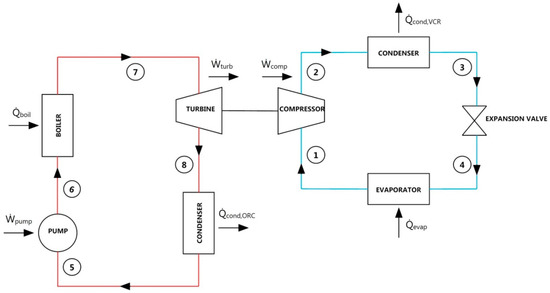
Figure 1.
Schematic of combined ORC-single evaporator VCR cycle.
Assumptions made for thermodynamic analysis are as follow.
- Cooling load is 2 kW.
- Fluid is saturated vapor at the outlet of evaporator and boiler while being saturated liquid at the outlet of both of the condensers [3,10,11,13].
- 15 °C temperature difference was assumed to be between boiler and waste heat source [13,20].
- 5 °C temperature difference was assumed to be between evaporator and refrigerated space [13,21,22].
- Ambient temperature and pressure are 25 °C and 101.325 kPa, respectively.
- Heat sink temperatures of both of the condensers are equal to ambient temperature.
Input values and ranges of operational parameters used in combined a ORC-single evaporator VCR cycle are given in Table 2.

Table 2.
Input values and ranges of operational parameters used in first system.
Figure 2 shows a schematic of the combined system with dual evaporator in VCR cycle. System targets transmitting turbine power gained in ORC to the compressor of VCR to achieve refrigeration. Cooling loads of evaporators were selected to be consistent with similar studies. The system uses the same working fluid in both of the combined cycles. Compression occurs in the compressor. Then, heat is transferred to ambient under constant pressure in condenser. After the condenser, fluid divides into two branches to achieve refrigeration mission in two different evaporators. Fluid expands in the second expansion valve under constant enthalpy and passes through the second evaporator to draw heat of the ambient to be refrigerated under constant pressure. Then, fluid expands in the third expansion valve under constant enthalpy to have the same pressure with fluid flowing from other branch at the entrance of mixing chamber. On the other hand, fluid expands in the first expansion valve under constant enthalpy and passes through the first evaporator to draw heat of the ambient to be refrigerated under constant pressure. Fluids flowing from two branches mix in mixing chamber and are directed to compressor. Thus, VCR cycle is completed. In the organic Rankine cycle, pumping occurs in the pump. Later, temperature of the fluid increases by heating it with hot water waste heat source under constant pressure in the boiler. Expansion happens in the turbine and turbine power is given to compressor. Lastly, heat is transferred to ambient under constant pressure in condenser and ORC cycle is finished.
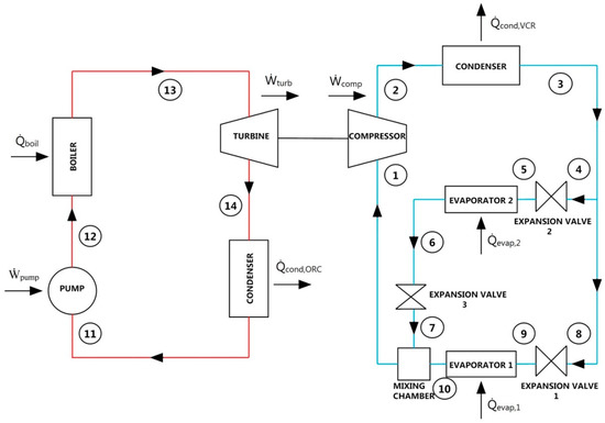
Figure 2.
Schematic of combined ORC-dual evaporator VCR cycle.
Assumptions made for thermodynamic analysis are as follow.
- Cooling load is 4 kW for the first evaporator while being 2 kW for the second evaporator.
- Fluid is saturated vapor at the outlet of both of evaporators and boiler while being saturated liquid at the outlet of both of the condensers [3,10,11,13].
- 15 °C temperature difference was assumed to be between boiler and waste heat source [13,20].
- 5 °C temperature difference was assumed to be between both of evaporators and their refrigerated spaces [13,21,22].
- Ambient temperature and pressure are 25 °C and 101.325 kPa, respectively.
- Heat sink temperatures of both of the condensers are equal to ambient temperature.
Input values and ranges of operational parameters used in combined ORC-dual evaporator VCR cycle are given in Table 3.

Table 3.
Input values and ranges of operational parameters used in the second system.
3. Thermodynamic Analysis
All of the equations that are necessary for performing energy and exergy analysis of combined cycles are presented below. While making calculations, systems were considered to operate under steady-state conditions. Heat and pressure losses in pipes and components were neglected. Both of proposed systems have similar equations since they have the same components and working principle.
3.1. Combined ORC-Single Evaporator VCR Cycle Equations
Exergy of a point can be expressed as:
Flow exergy of any point in the system can be expressed as:
Thermal and exergy efficiency calculations for combined ORC-single evaporator VCR cycle can be seen from below mentioned equations.
Coefficient of performance of refrigeration cycle:
Thermal efficiency of ORC:
Coefficient of performance of combined system:
Carnot efficiency of ORC:
Exergy efficiency of ORC:
Carnot coefficient of performance:
Exergy efficiency of refrigeration cycle:
Exergy efficiency of combined system:
Energy and exergy equations related to components in refrigeration cycle of combined system are given in Table 4.

Table 4.
Equations for VCR cycle components in combined ORC-single evaporator VCR cycle.
Energy and exergy equations related to components in the organic Rankine cycle of combined system are given in Table 5.

Table 5.
Equations for ORC cycle components in combined ORC-single evaporator VCR cycle.
3.2. Combined ORC-Dual Evaporator VCR Cycle Equations
Thermal and exergy efficiency calculations for the combined ORC-dual evaporator VCR cycle can be observed from below mentioned equations.
Coefficient of performance of refrigeration cycle:
Thermal efficiency of ORC is the same as Equation (4). Also, coefficient of performance of the combined system can be calculated from Equation (5). Carnot and exergy efficiency of formulas for ORC can be seen from Equations (6) and (7), respectively.
Exergy efficiency of refrigeration cycle for dual evaporator system is given in Equation (12). This value can be calculated by dividing the sum of exergies transferred with heat in the evaporators to compressor power.
Finally, exergy efficiency of combined system can be calculated from Equation (10).
Energy and exergy equations related to components in refrigeration cycle of combined system are given in Table 6.

Table 6.
Equations for VCR cycle components in combined ORC-dual evaporator VCR cycle.
Energy and exergy equations related to components in the organic Rankine cycle of combined system are given in Table 7.

Table 7.
Equations for ORC cycle components in combined ORC-dual evaporator VCR cycle.
4. Results and Discussion
Thermodynamic models for two proposed systems were formed in the Engineering Equation Solver, and all of the above mentioned equations were solved in this software using R1234ze(E), R227ea, R134a, and R600a working fluids [23]. Effects of different parameters on COPsys, ηex,sys, and ṁtotal were graphed. The most efficient working fluid was detected looking at these graphs. After determination of the most efficient working fluid, second law efficiency, exergy destruction rate, exergy destruction ratio, and degree of thermodynamic perfection were detected for components in both of proposed systems using this fluid.
Mathematical model of the system was validated comparing its results for R1234ze(E) with the results of Saleh [11]. evap of 136.3 kW, COPVCR of 4.84, Ẇturb of 28.17 kW, and of 11.26% was found by Saleh [11] while our model suggests evap of 135.7 kW, COPVCR of 4.868, Ẇturb of 27.88 kW, and of 11.22%.
4.1. Combined ORC-Single Evaporator VCR Cycle Results
Figure 3 represents effect of evaporator temperature on COPsys, ηex,sys, and ṁtotal. Increase in evaporator temperature leads to a rise in coefficient of performance of system. As the evaporator temperature increases, compressor power decreases, and thus leading to an increase in COPVCR. For this reason, COPsys increases as well according to Figure 3a. Increase in evaporator temperature has a negative effect on exergy efficiency of system according to Figure 3b. Exergy transferred with heat in evaporator decreases as a result of increase in evaporator temperature. This situation effects ηex,VCR negatively, thereby reducing ηex,sys. Figure 3c states that, increase in evaporator temperature causes a decrease in total mass flow rate. Because of the fact that compressor power decreases with increasing evaporator temperature, turbine power decreases as well. Decrease in turbine power causes decline in ṁORC. Therefore, total mass flow rate of combined system decreases too. It can be detected from Figure 3 that R600a achieves the best COPsys and ηex,sys and can be labelled as the most efficient working fluid.
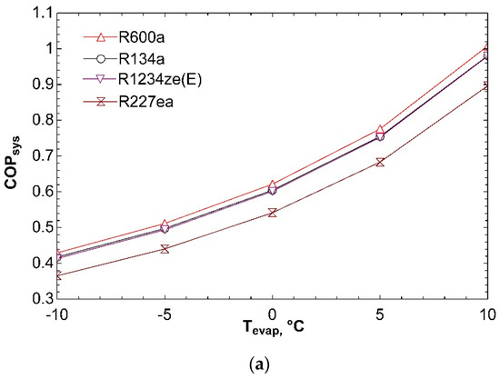
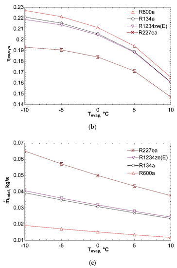
Figure 3.
Effect of Tevap on COPsys (a), ηex,sys (b), and ṁtotal (c) in combined ORC-single evaporator VCR cycle.
Figure 4 shows influence of temperature of condenser in VCR cycle on system performance. As condenser temperature rises from 30 °C to 50 °C, condenser pressure and exit enthalpy of compressor increase. For this reason, compressor power increases and COPVCR is negatively affected. This situation causes fall in COPsys and can be seen from Figure 4a. ηex,sys declines with increase in condenser temperature as presented in Figure 4b. The reason is increase of compressor power and thus decrease in exergy efficiency of refrigeration cycle. If ηex,VCR declines, ηex,sys decreases as well according to Equation (10). Figure 4c represents that increase in condenser temperature leads to rise in ṁtotal. Since compressor power increases as a result of increasing condenser temperature, ṁVCR increases. Turbine power is also positively affected from this condition because compressor is directly connected to turbine. As a result, ṁORC rises as well. For these reasons, total mass flow rate of combined system increases. R227ea shows maximum mass flow rate since it has the highest molecular mass.
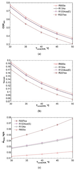
Figure 4.
Influence of Tcond,VCR on COPsys (a), ηex,sys (b), and ṁtotal (c) in combined ORC-single evaporator VCR cycle.
Figure 5 depicts impact of compressor isentropic efficiency on system performance. Change of isentropic efficiency from 0.65 to 0.85 increases COPsys as can be seen from Figure 5a. Compressor power decreases with increasing isentropic efficiency. So, COPVCR and, consequently, COPsys rise. Decline in compressor power increases exergy efficiency of refrigeration cycle and thereby increasing ηex,sys for all fluids as given in Figure 5b.
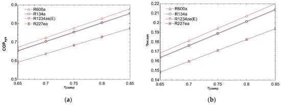
Figure 5.
Impact of ηcomp on COPsys (a) and ηex,sys (b) in combined ORC-single evaporator VCR cycle.
Figure 6 indicates how system performance is affected by boiler temperature. The effect of boiler temperature on COPsys is exhibited in Figure 6a. It can be observed from figure that increase of boiler temperature from 60 °C to 100 °C effects positively coefficient of performance of combined system. Turbine inlet enthalpy rises with increasing boiler temperature. To satisfy constant compressor and turbine power, ṁORC must decrease. For this reason, heat input to boiler decreases and ηORC increases according to Equation (4). Rise in ηORC increases COPsys. Increase in thermal efficiency of ORC also causes rise in ηex,ORC according to Equation (7). So, ηex,sys goes up for all fluids as depicted in Figure 6b. Critical temperatures of R134a and R227ea are 101.1 °C and 101.8 °C, respectively. Vapor at 100 °C will have low enthalpy and so expansion will end in two-phase region. This is dangerous for turbine and decreases efficiency as seen in Figure 6b. The total mass flow rate decreases with increasing boiler temperature for all fluids as given in Figure 6c. The reason for that is decrease of ṁORC as mentioned in explanation of Figure 6a. Decline in ṁORC effects negatively total mass flow rate.
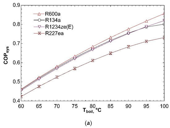
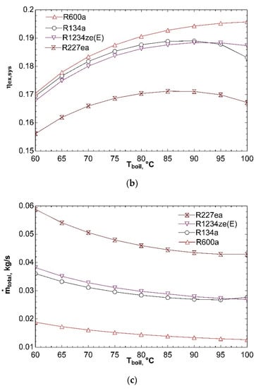
Figure 6.
Effect of Tboil on COPsys (a), ηex,sys (b), and ṁtotal (c) in combined ORC-single evaporator VCR cycle.
Figure 7 shows the effect of temperature of condenser in ORC on system performance. As condenser temperature increases, exit enthalpy of turbine increases. ṁORC must increase to ensure constant turbine power since there is no change in refrigeration cycle. Heat input to the boiler goes up with increasing ṁORC and ηORC decreases. For this reason, COPsys declines for all working fluids as can be seen from Figure 7a. Decrease in thermal efficiency of ORC as a result of increase in condenser temperature also causes falling in ηex,ORC. So, ηex,sys goes down for all working fluids as shown in Figure 7b. Total mass flow rate rises with increase of condenser temperature from 30 °C to 50 °C as presented in Figure 7c. ṁORC goes up because of reasons mentioned in interpretation of Figure 7a. As a result, increase in ṁORC leads to a rise in total mass flow rate of the system.
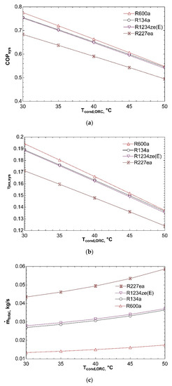
Figure 7.
Effect of Tcond,ORC on COPsys (a), ηex,sys (b), and ṁtotal (c) in combined ORC-single evaporator VCR cycle.
Figure 8 explains how system performance is influenced with turbine isentropic efficiency. Increase of turbine isentropic efficiency tends to rise COPsys as shown in Figure 8a. Specific turbine work increases as isentropic efficiency goes up. ṁORC needs to decrease to maintain constant turbine power. So, boil declines and thereby ηORC increases. COPsys goes up concerning increase in thermal efficiency of ORC. Ƞex,ORC is positively affected with increase of ηORC according to Equation (7). Because there is no change in VCR cycle, ηex,VCR remains constant. Increase in ηex,ORC leads to rise in ηex,sys according to Equation (10) and this can be seen for all working fluids from Figure 8b.
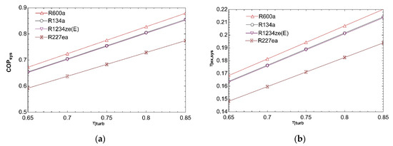
Figure 8.
Influence of ηturb on COPsys (a) and ηex,sys (b) in combined ORC-single evaporator VCR cycle.
Figure 9 indicates effect of ambient temperature on coefficient of performance of system. While investigating influence of change of ambient temperature, we assumed to be 5 °C temperature difference between ambient and condensers. This temperature difference was only utilized while drawing this graph. Previous Figure 3, Figure 4, Figure 5, Figure 6, Figure 7 and Figure 8 accepted constant ambient temperature. It can be seen from this graph that increasing ambient temperature leads to decrease in COPsys. The reason of this situation is rise in compressor power.
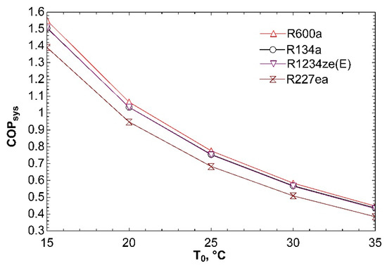
Figure 9.
Effect of T0 on COPsys in combined ORC-single evaporator VCR cycle.
Graphs of the combined ORC-single evaporator VCR cycle show complete accordance with previous studies [2,3,10,11,13,15]. It can be clearly stated from these figures that R600a achieves best system performance and can be selected as the most efficient working fluid among proposed four fluids. Using R600a, T-s and P-h diagrams of the system can be observed from Figure 10a,b, respectively.
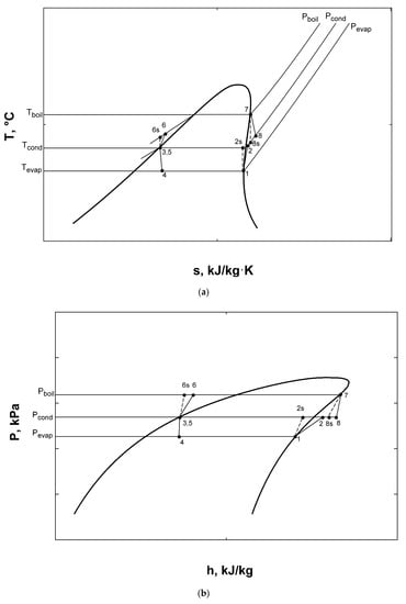
Figure 10.
T-s (a) and P-h (b) diagrams for combined ORC-single evaporator VCR cycle.
Exergy destruction rate and exergy destruction ratio of each component in the system can be seen from Figure 11a,b, respectively. Calculations were performed using input values in Table 2 at 25 °C ambient temperature. It can be seen from these figures that highest exergy destruction in combined system occurs in boiler with 35%. In addition, the component that has the highest exergy destruction in refrigeration cycle is compressor.
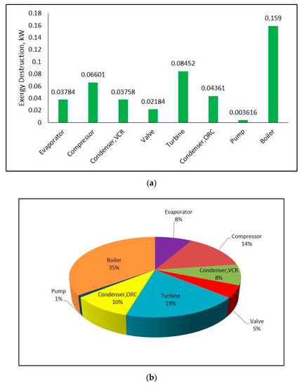
Figure 11.
Exergy destruction rate (a) and exergy destruction ratio (b) of components in combined ORC-single evaporator VCR cycle.
Second law efficiency and degree of thermodynamic perfection for each component in the system can be observed from Figure 12a,b, respectively. Figure 12a explains that the pump has the greatest second law efficiency in combined system. The reason why second law efficiencies of both of the condensers are zero is that exergy transferred with heat in condensers are equal to zero since their heat sink temperatures are equivalent to ambient temperature. While heat is transferred to ambient, exergy of the working fluid is totally lost in the condenser. In addition, there is zero exergy transfer in expansion valve. There is only exergy destruction in the valve and so its second law efficiency is equal to zero. The component giving the highest degree of thermodynamic perfection is pump according to Figure 12b. If Figure 12a,b are compared, it can be seen that there is a difference between second law efficiency and degree of thermodynamic perfection of some components. This situation results that second law efficiencies of components can be improved as much as their difference from degree of thermodynamic perfection, thereby some more exergy can be gained.
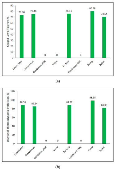
Figure 12.
Second law efficiency (a) and degree of thermodynamic perfection (b) for each component in combined ORC-single evaporator VCR cycle.
4.2. Combined ORC-Dual Evaporator VCR Cycle Results
Figure 13 indicates effect of temperature of first evaporator on COPsys, ηex,sys, and ṁtotal. COPsys increases as temperature of first evaporator increases according to Figure 13a. When Tevap,1 rises, pressure and enthalpy at the exit of first evaporator increases. This condition causes an increase of enthalpy at compressor inlet and compressor power decreases. For this reason, COPVCR and thereby COPsys increases. Figure 13b shows that there is not a significant change in exergy efficiency of the combined system. Exergy transferred with heat in first evaporator decreases with increase in its temperature. This situation tries to decrease ηex,VCR according to Equation (12). However, decrease in compressor power tries to increase ηex,VCR with respect to same equation. Consequently, ηex,VCR and therefore ηex,sys almost remain the same. Increase in Tevap,1 causes decrease in ṁtotal as represented in Figure 13c. Due to the fact that compressor power decreases with rise in temperature of first evaporator, turbine power declines too. ṁORC decreases in connection with decrease in turbine power. As a result, total mass flow rate of combined system decreases as well.
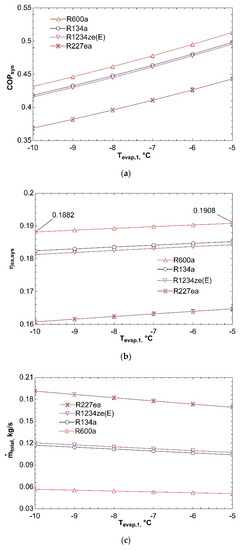
Figure 13.
Effect of Tevap,1 on COPsys (a), ηex,sys (b), and ṁtotal (c) in combined ORC-dual evaporator VCR cycle.
Figure 14 clarifies how system performance is impacted with temperature of second evaporator. Increase of Tevap,2 from 0 °C to 10 °C does not cause an important change in COPsys as can be detected from Figure 14a. As Tevap,2 rises, pressure and enthalpy at the exit of second evaporator increases. It is normally expected to affect this condition inlet pressure to the compressor. Hence, the third expansion valve, which is basically an evaporator pressure regulator, ensures that fluid has the same pressure with fluid flowing from the other branch at the inlet of mixing chamber. For this reason, pressure at the inlet of compressor does not change. On the other hand, enthalpy at the inlet of compressor is not importantly effected by increase of Tevap,2 since mass flow rate flowing through first evaporator is twice higher than that of second evaporator, thus an increase of h10 has a greater effect than h7 on h1 according to energy equation for mixing chamber given in Table 6. For these reasons, compressor power does not change significantly with increase in Tevap,2. As a result, both COPVCR and COPsys almost remain unchanged. Figure 14b represents that ηex,sys declines with increasing Tevap,2. Because of the fact that compressor power is not considerably effected by increase in Tevap,2, the most important parameter that influences ηex,VCR is the exergy transferred by heat in second evaporator according to Equation (12). Increase in Tevap,2 causes reduction in . So, ηex,VCR and, thus, ηex,sys decline. Effect of Tevap,2 on ṁtotal is depicted in Figure 14c. It can be seen that ṁtotal is not impacted by increase of Tevap,2. The reason of this situation can be thought to be not changing of compressor power and thus turbine power. ṁORC does not change if there is no change in turbine power. In addition, ṁVCR almost remains the same because of assumption of constant cooling loads. Eventually, ṁtotal does not change.
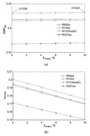
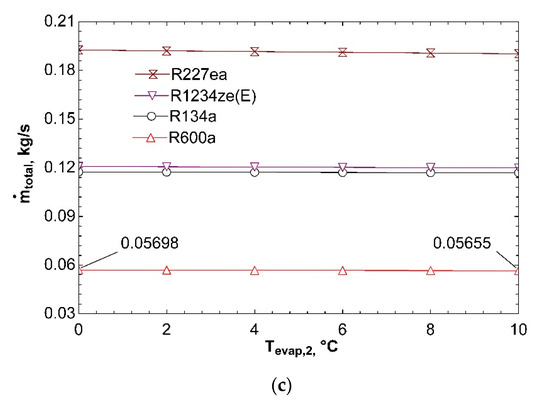
Figure 14.
Impact of Tevap,2 on COPsys (a), ηex,sys (b), and ṁtotal (c) in combined ORC-dual evaporator VCR cycle.
Figure 15 shows influence of change of ambient temperature on COPsys for dual evaporator system. We accepted to be 5 °C temperature difference between ambient and condensers while investigating effect of ambient temperature. Temperature difference of 5 °C was only used while drawing this graph. Previous Figure 13 and Figure 14 assume ambient temperature to be constant. According to graph, increase in ambient temperature causes decrease in COPsys. Because of the fact that compressor power will go up with increase in ambient temperature, COPsys will decrease.
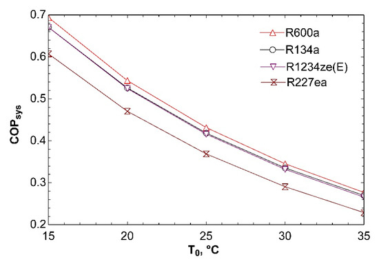
Figure 15.
Influence of T0 on COPsys in combined ORC-dual evaporator VCR cycle.
Graphs indicating effect of boiler and condenser temperatures as well as turbine and compressor isentropic efficiencies on system performance for the combined ORC-dual evaporator VCR cycle were not included in this article since their tendencies are exactly the same as combined ORC-single evaporator VCR cycle.
It can be observed from Figure 13 and Figure 14 that R600a gives best COPsys and ηex,sys, therefore can be selected as the most efficient working fluid among four fluids. Using R600a, T-s and P-h diagrams of the system are depicted in Figure 16a,b, respectively.
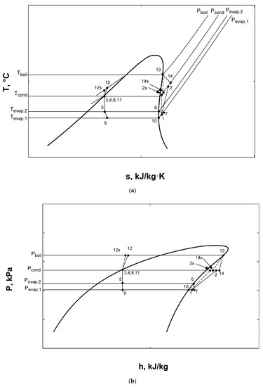
Figure 16.
T-s (a) and P-h (b) diagrams for combined ORC-dual evaporator VCR cycle.
Figure 17a,b show exergy destruction rate and exergy destruction ratio of each component in the system, respectively. Calculations were carried out using input values in Table 3 at a 25 °C ambient temperature. It can be observed from these figures that highest exergy destruction in combined system occurs in boiler. It causes more than one third of total exergy destruction. The least amount of exergy destruction happens in the mixing chamber with almost negligible amount. Also, the component that has the highest exergy destruction in refrigeration cycle is the compressor. The reason why the third valve has exergy destruction rate of equal to sum of the first and second valves is that vapor is expanded in valve three. Expansion of vapor will produce much more entropy than expansion of liquid as in first and second valves.
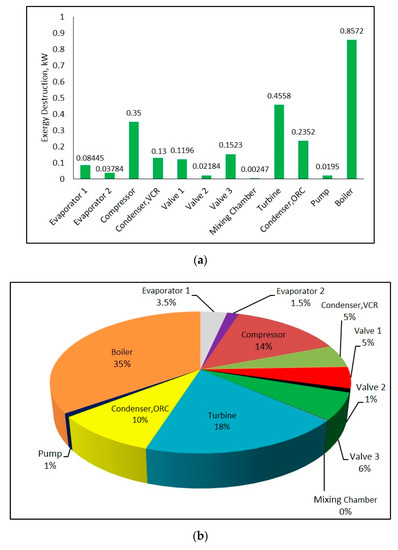
Figure 17.
Exergy destruction rate (a) and exergy destruction ratio (b) of components in combined ORC-dual evaporator VCR cycle.
Figure 18a,b depict the second law efficiency and degree of thermodynamic perfection for each component in the system, respectively. The component having the biggest second law efficiency in combined system is mixing chamber as represented in Figure 18a. This is followed by first evaporator and pump. The reason for zero second law efficiency in both of condensers is equivalent heat sink and ambient temperatures. Also, all of the expansion valves have zero second law efficiency since there are no exergy transfer in valves. Figure 18b indicates that pump gives the highest degree of thermodynamic perfection. As in combined system with single evaporator, the difference between second law efficiency and degree of thermodynamic perfection of some components exists for this system too. This situation explains that theoretical ultimate point is not reached in terms of exergy. More exergy can be achieved as much as difference between second law efficiency and degree of thermodynamic perfection.
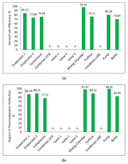
Figure 18.
Second law efficiency (a) and degree of thermodynamic perfection (b) for each component in combined ORC-dual evaporator VCR cycle.
4.3. Comparison of Two Combined Systems
Using R600a and input values given in Table 2 and Table 3, general comparison of proposed two systems can be seen from Table 8. A 44% decrease in COPsys occurs when dual evaporator is used instead of a single evaporator in refrigeration part of the combined system. Also, ηex,sys decreases with the addition of an extra evaporator. Moreover, compressor power, total exergy destruction rate, and total mass flow rate are observed to be higher in dual evaporator system when compared to single evaporator system. The reason of increase in compressor power is that heat is removed at higher temperature in the second evaporator while vapor must be compressed from the lower pressure of the first evaporator.

Table 8.
Comparison of proposed systems.
5. Conclusions
R600a has been selected as the most efficient working fluid among the proposed four working fluids according to results of the study. Besides its performance, it is important to take into consideration global warming potential and ozone depletion potential of the fluid while selecting the most efficient working fluid. At this point, R600a has zero ODP and less GWP when compared most of used working fluids.
High evaporator and boiler temperatures as well as high turbine and compressor isentropic efficiencies have great effect to achieve best COPsys. In addition, low condenser temperature causes rise in COPsys. To get better ηex,sys, evaporator and condenser temperatures should be decreased. Also, high boiler temperature, high turbine and compressor isentropic efficiencies enhance ηex,sys.
The highest exergy destruction occurs in the boiler in both of the combined systems no matter whether its with the single evaporator or dual evaporator. The highest exergy destruction happens in the compressor in the refrigeration cycle of both of combined systems.
The pump has the biggest second law efficiency in combined system with single evaporator. For combined system with dual evaporator, mixing chamber takes the lead in terms of second law efficiency. The component that shows the highest degree of thermodynamic perfection is pump in both of combined systems.
Component size that is one of design parameters has not been included in this study. We suggest researchers to consider component size in their further studies.
As a result, addition of an extra evaporator in combined system causes a significant decrease in COPsys and reduces ηex,sys. Total exergy destruction also increases with an additional evaporator.
Author Contributions
O.P. and H.I.A. designed and analyzed proposed systems. O.P. wrote the paper.
Funding
This research received no external funding.
Conflicts of Interest
The authors declare no conflict of interest.
Nomenclature
| COP | coefficient of performance |
| e | specific exergy (kJ/kg) |
| exergy rate (kW) | |
| EDR | exergy destruction ratio |
| GWP | global warming potential |
| h | specific enthalpy (kJ/kg) |
| ṁ | mass flow rate (kg/s) |
| NBP | normal boiling point |
| ODP | ozone depletion potential |
| ORC | organic Rankine cycle |
| P | pressure (kPa) |
| heat transfer rate (kW) | |
| s | specific entropy (kJ/kg·K) |
| T | temperature (°C) |
| VCR | vapor compression refrigeration |
| Ẇ | power (kW) |
| Greek symbols | |
| efficiency | |
| degree of thermodynamic perfection | |
| Subscripts | |
| boil | boiler |
| comp | compressor |
| cond | condenser |
| dest | destruction |
| ev | expansion valve |
| evap | evaporator |
| ex | exergy |
| H | high temperature reservoir |
| i | state point |
| L | low temperature reservoir |
| mc | mixing chamber |
| sys | system |
| turb | turbine |
| 0 | ambient |
| II | second law |
References
- Qiu, G. Selection of working fluids for micro-CHP systems with ORC. Renew. Energy 2012, 48, 565–570. [Google Scholar] [CrossRef]
- Saleh, B. Parametric and working fluid analysis of a combined organic Rankine-vapor compression refrigeration system activated by low-grade thermal energy. J. Adv. Res. 2016, 7, 651–660. [Google Scholar] [CrossRef] [PubMed]
- Cihan, E.; Kavasogullari, B. Energy and exergy analysis of a combined refrigeration and waste heat driven organic rankine cycle system. Therm. Sci. 2017, 21, 2621–2631. [Google Scholar] [CrossRef]
- Bao, J.; Zhao, L. A review of working fluid and expander selections for organic Rankine cycle. Renew. Sustain. Energy Rev. 2013, 24, 325–342. [Google Scholar] [CrossRef]
- Mahmoudi, A.; Fazli, M.; Morad, M.R. A recent review of waste heat recovery by Organic Rankine Cycle. Appl. Therm. Eng. 2018, 143, 660–675. [Google Scholar] [CrossRef]
- Hung, T.C.; Shai, T.Y.; Wang, S.K. A review of organic Rankine cycles (ORCs) for the recovery of low-grade waste heat. Energy 1997, 22, 661–667. [Google Scholar] [CrossRef]
- Desai, N.B.; Bandyopadhyay, S. Process integration of organic Rankine cycle. Energy 2009, 34, 1674–1686. [Google Scholar] [CrossRef]
- Tchanche, B.F.; Lambrinos, G.; Frangoudakis, A.; Papadakis, G. Low-grade heat conversion into power using organic Rankine cycles—A review of various applications. Renew. Sustain. Energy Rev. 2011, 15, 3963–3979. [Google Scholar] [CrossRef]
- Moles, F.; Navarro-Esbri, J.; Peris, B.; Mota-Babiloni, A.; Kontomaris, K. Thermodynamic analysis of a combined organic Rankine cycle and vapor compression cycle system activated with low temperature heat sources using low GWP fluids. Appl. Therm. Eng. 2015, 87, 444–453. [Google Scholar] [CrossRef]
- Li, H.; Bu, X.; Wang, L.; Long, Z.; Lian, Y. Hydrocarbon working fluids for a Rankine cycle powered vapor compression refrigeration system using low-grade thermal energy. Energy Build. 2013, 65, 167–172. [Google Scholar] [CrossRef]
- Saleh, B. Energy and exergy analysis of an integrated organic Rankine cycle-vapor compression refrigeration system. Appl. Therm. Eng. 2018, 141, 697–710. [Google Scholar] [CrossRef]
- Aphornratana, S.; Sriveerakul, T. Analysis of a combined Rankine–vapour–compression refrigeration cycle. Energy Convers. Manag. 2010, 51, 2557–2564. [Google Scholar] [CrossRef]
- Lizarte, R.; Palacios-Lorenzo, M.E.; Marcos, J.D. Parametric study of a novel organic Rankine cycle combined with a cascade refrigeration cycle (ORC-CRS) using natural refrigerants. Appl. Therm. Eng. 2017, 127, 378–389. [Google Scholar] [CrossRef]
- Sun, W.; Yue, X.; Wang, Y. Exergy efficiency analysis of ORC (Organic Rankine Cycle) and ORC-based combined cycles driven by low-temperature waste heat. Energy Convers. Manag. 2017, 135, 63–73. [Google Scholar] [CrossRef]
- Rawat, K.S.; Khulve, H.; Pratihar, A.K. Thermodynamic Analysis of Combined ORC-VCR System Using Low Grade Thermal Energy. Int. J. Res. Appl. Sci. Eng. Technol. 2015, 3, 515–522. [Google Scholar]
- Wang, N.; Chen, J. Theoretical Analysis of Organic Rankine Cycle Combine Power and Ejector Refrigeration Driven By Solar Energy. Energy Procedia 2018, 152, 109–114. [Google Scholar] [CrossRef]
- Tauseef-Nasir, M.; Chun-Kim, K. Working fluids selection and parametric optimization of an Organic Rankine Cycle coupled Vapor Compression Cycle (ORC-VCC) for air conditioning using low grade heat. Energy Build. 2016, 129, 378–395. [Google Scholar] [CrossRef]
- Yang, X.; Zhao, L. Thermodynamic analysis of a combined power and ejector refrigeration cycle using zeotropic mixtures. Energy Procedia 2015, 75, 1033–1036. [Google Scholar] [CrossRef][Green Version]
- Calm, J.M.; Hourahan, G.C. Physical, safety, and environmental data summary for current and alternative refrigerants. In Proceedings of the 23rd International Congress of Refrigeration, Prague, Czech Republic, 21–26 August 2011; pp. 1–22. [Google Scholar]
- Fankam-Tchanche, B.; Papadakis, G.; Lambrinos, G.; Frangoukadis, A. Fluid selection for a low-temperature solar organic Rankine cycle. Appl. Therm. Eng. 2009, 29, 2468–2476. [Google Scholar] [CrossRef]
- Alberto-Dopazo, J.; Fernandez-Seara, J.; Sieres, J.; Uhia, F.J. Theoretical analysis of a CO2–NH3 cascade refrigeration system for cooling applications at low temperatures. Appl. Therm. Eng. 2009, 29, 1577–1583. [Google Scholar] [CrossRef]
- Bai, T.; Yan, G.; Yu, J. Thermodynamics analysis of a modified dual-evaporator CO2 transcritical refrigeration cycle with two-stage ejector. Energy 2015, 84, 325–335. [Google Scholar] [CrossRef]
- Klein, S.A. Engineering Equation Solver (EES); Academic Professional Version; F-Chart Software: Middleton, WI, USA, 2013. [Google Scholar]
© 2019 by the authors. Licensee MDPI, Basel, Switzerland. This article is an open access article distributed under the terms and conditions of the Creative Commons Attribution (CC BY) license (http://creativecommons.org/licenses/by/4.0/).