Article

A Feasibility Study for Using Fishnet to Protect Offshore Wind Turbine Monopile Foundations from Damage by Scouring

1
Department of Mechanical Engineering, Hunan Institute of Engineering, Xiangtan 411104, China
2
Hunan Province Engineering Laboratory of Wind Power Operation, Maintenance and Testing Technology, Xiangtan 411104, China
3
School of Engineering, Newcastle University, Newcastle Upon Tyne NE1 7RU, UK
*
Authors to whom correspondence should be addressed.
Appl. Sci. 2019, 9(23), 5023; https://doi.org/10.3390/app9235023
Submission received: 11 September 2019 / Revised: 17 November 2019 / Accepted: 18 November 2019 / Published: 21 November 2019
(This article belongs to the Special Issue Wind Power Technologies)

Abstract

:
Offshore wind turbine monopile foundations are subjected to complex wind, wave, and flow coupling effects, which result in seabed scouring around the monopile. The consequent scour pits threaten the reliability, safety, and load-carrying capacity of the monopile. In order to develop a cost-effective measure to mitigate such an issue, a new countermeasure device, named “fishnet”, is studied in this paper using a combined approach of numerical simulations and experimental tests. In the research, the size of the fishnet, diameter of the fishnet thread, and the installation height of the fishnet were optimized in order to achieve the best protection to the monopile foundation. In the paper, both numerical simulations and laboratory tests proved the effectiveness of the proposed “fishnet” in reducing the scour around the wind turbine monopile foundations. Moreover, its contribution to erosion reduction can be further enhanced via optimization. It was found that, after optimization, the maximum shear force on the seabed could be reduced by 14% in the numerical study, and the maximum depth of the scour pit could be reduced by 38.2% in laboratory tests.

1. Introduction

Offshore wind was rapidly developed across the world in recent years [1]. The global installed capacity of offshore wind is predicted to reach 46.4 GW by the end of 2022, of which 33.9 GW will be installed in Europe, 11.3 GW in Asia, and 1.2 GW in North America [2]. At present, most offshore wind turbines are installed in shallow waters, and more than 70% of them are supported by large-diameter monopiles [3]. Usually, there are relatively stronger tidal currents in the nearshore shallow waters, where the bulky monopile foundations are more prone to being affected. In other words, during the long service life of an offshore wind turbine, it withstands complex wind, wave, and tidal current in the harsh marine environment. The superposition of these factors often leads to a complex flow field around its monopile foundation, resulting in significant shear stress on the seabed and seabed erosion around the foundation [4]. Scour pits around the offshore wind turbine foundations were first observed at the Egmond aan Zee Wind Farm in the Netherlands. Dong Energy later reported a similar problem for their offshore wind farms at the Burbo Bank and Gunfleet Sands [5]. They are produced by the downflows in front, horseshoe vortices and the annular acceleration water flow on both sides and behind the monopile foundations. These vortices stir and take away the sand and soil on the seabed and finally produce scour pits in the end around the monopiles [6]. The consequent scour pits reduce the depth of the pile foundation into the soil, thereby changing the natural frequency of the wind turbine foundation and causing an adverse effect on the dynamic response, reliability, and safety of the whole wind turbine structure. Research showed that scour pits can reduce the ultimate bearing capacity of the monopile by 35% and increase the bending moment of the monopile by 48%–60% [7].
In fact, the scouring phenomenon was long noted in bridge engineering, and much effort was made before in order to address such issues suffered by bridge piers [8,9,10,11]. The achieved techniques can be roughly classified into two categories. The first category of techniques reduces scour mainly by adding sacrificial piles [12,13] or changing the flow direction via guide panels [14], surface guide panels [15,16], slots through the piers [15], and so on. The second category of techniques reduces scour using the approach of bed armoring. For example, hard engineering materials, such as blocks, rack ripraps [17,18,19], and gravel bags [20], are applied on the seabed around the pier to prevent excessive scouring. However, these protective measures have limitations, and not all of them are suited for application to protecting offshore wind turbines. For example, the effectiveness of those technologies developed for changing flow direction is very sensitive to the direction of flow. They may work very well in river, where the water direction is relatively constant over time. However, the direction of tidal current in the marine environment may change all the time, and the riprap technology is difficult to maintain in river. It becomes more difficult to apply this technology in the harsh offshore environment. Moreover, the use of professional vessels to transport and place large quantities of stones and sandbags on the target seabed causes additional costs, let alone the challenges of recycling them in decommission; a slot or hole can be opened on a bridge pier. However, it is definitely unacceptable to do this on the monopile foundation of an offshore wind turbine, as that may threaten the safety of the turbine structure. In summary, although much effort was made to reduce the scouring around bridge piers, few of the achieved techniques are applicable to protecting offshore wind turbine foundations. This motivated scholars to develop erosion reduction techniques dedicated to offshore wind turbine foundations. For example, a unique countermeasure device was developed in Reference [3]. However, the application of this technique still involves the installation of a large device on the seabed, which is costly. Moreover, its application needs a flat surface of the seabed. Such a requirement cannot be always satisfied in real life. All these constraints limit the application of that technique. Therefore, it can be said that, to date, there is no cost-effective erosion reduction technique that can be readily applied to offshore wind turbines.
Inspired by the spiral technology [21], a new countermeasure device, named “fishnet”, is proposed in this paper. Its effectiveness in reducing the scouring around the monopile foundation of offshore wind turbines was tested by both numerical studies and laboratory testing approaches. As compared to the existing erosion reduction measures, “fishnet” is more cost-effective and easier to be applied to monopile foundations of offshore wind turbines.

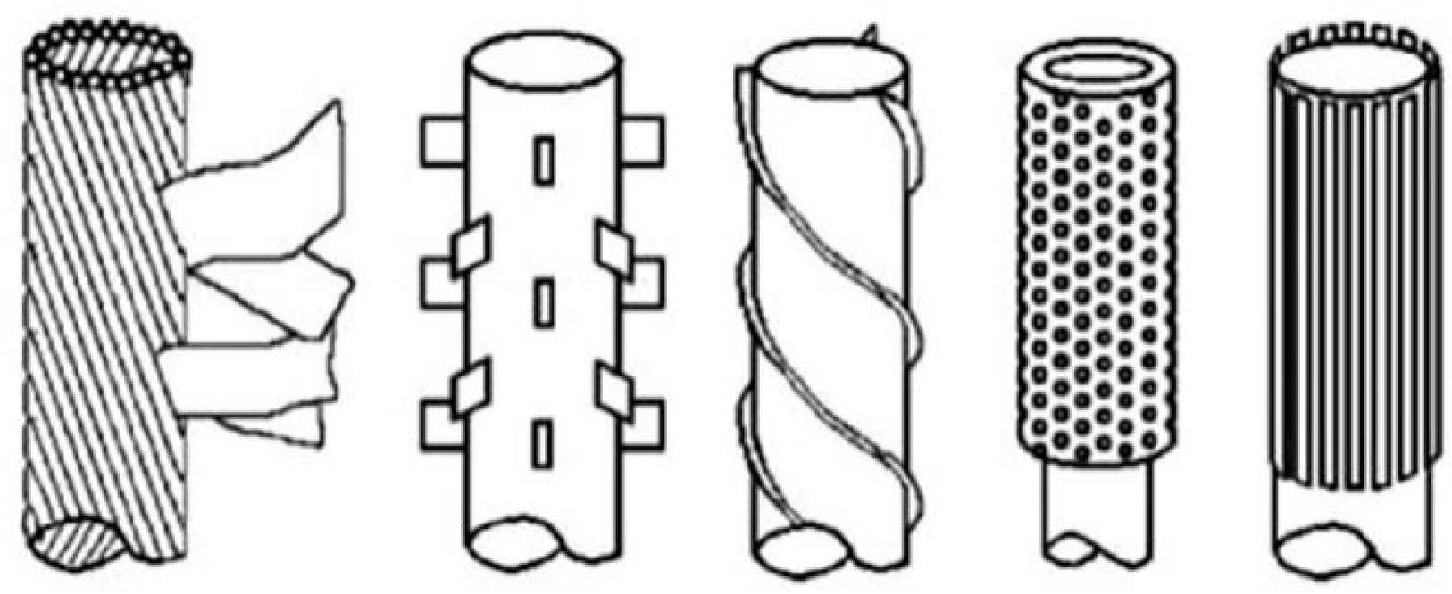
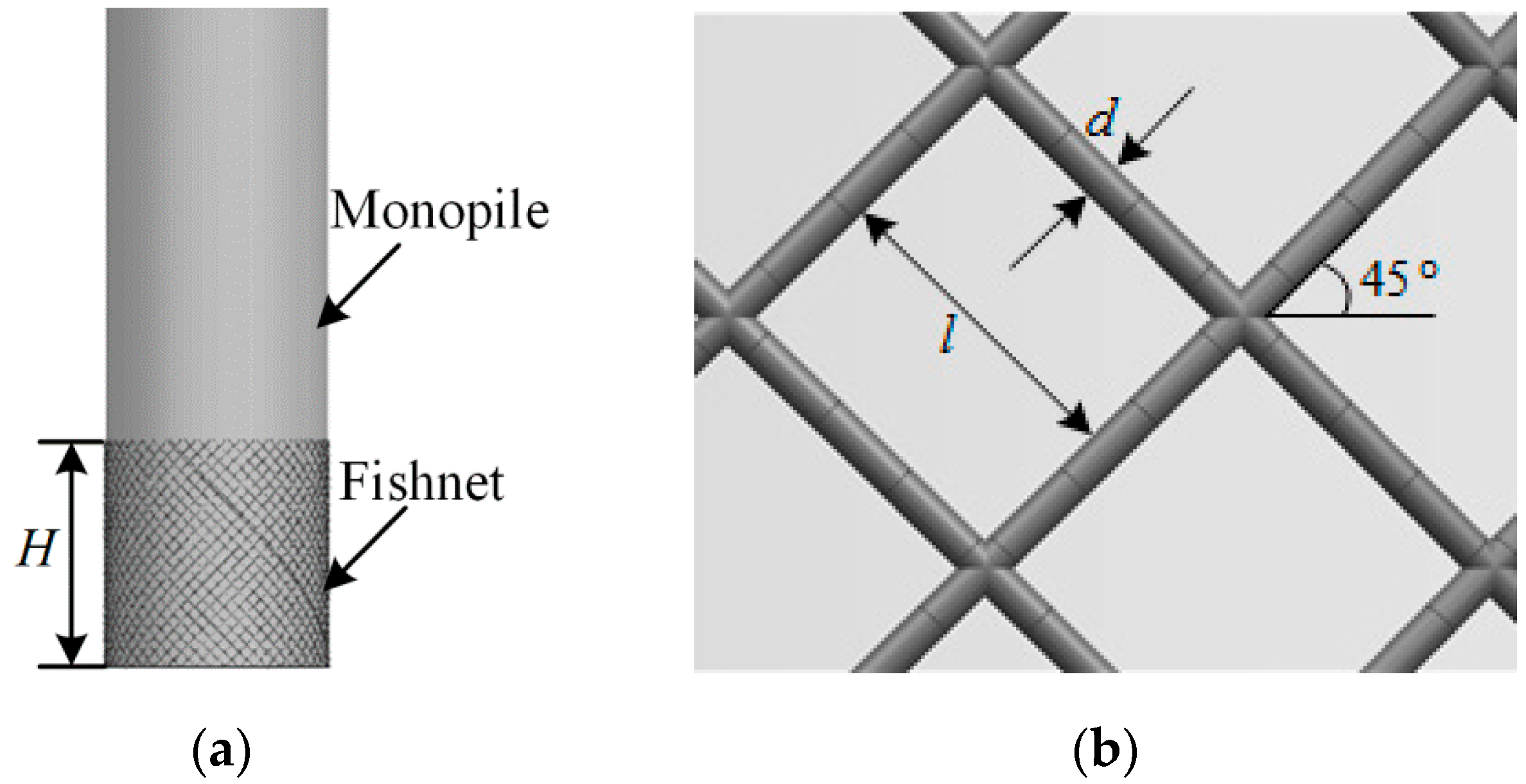
2. Working Mechanism of “Fishnet”

As mentioned earlier, when the tidal current reaches the monopile of an offshore wind turbine, downflows are produced in front of the monopile, which accelerate the current flow on both sides of the monopile. Then, horseshoe vortices and annular acceleration current flow occur on both sides of the monopile, and pairs of counter-rotating vortices also occur behind the monopile. The vortices erode the seabed constantly, stirring the sand and soil on the seabed around the monopile foundations. After the suspended soil and sand are taken away by the accelerated current flow, a scour pit is finally produced around the monopile.
The threaded pile anti-scouring technology borrowed from this paper was not initially applied to a monopile foundation of offshore wind turbines. Rather, it was applied to suppress the vortex-induced vibration of the cylinder structures in the offshore oil and gas industry and reduce the damage of these tubular structures by fatigue [22], as shown in Figure 1.
Changes in the surface roughness of the monopile (Figure 1) are one of the important measures for reducing vortices. For example, the threaded pile technique, wherein the spiral line attaches to the surface of the monopile, blocks the transmission of the circular acceleration water flow and interferes with the flow of downflow, thereby reducing the cyclic lateral force acting on the pile and limiting the vortices behind it. In theory, if these measures are applied to the surface of a wind turbine monopile foundation, they should also play an equal role in reducing the strengths of downflow and annular accelerated water flow. However, threaded technology has some limitations in practical applications. For example, its efficiency is sensitive to the angle of the threaded pile [21]. If a rope is directly tied to the monopile, the rope may be displaced and deformed due to the water pressure and water flow, which changes the thread angle of the rope and consequently reduces the efficiency of the device. Such an issue can be avoided if the spiral lines are welded on the monopile foundation of the offshore wind turbine, but welding operations in marine environment are very difficult and costly. This motivated the proposal of the “fishnet” technique in this paper. It is shown in Figure 2.
The fishnet increases the surface roughness of the monopile foundation and hinders the current flow’s separation from the surface of the monopile. Thus, the “fishnet” can successfully reduce the shedding of current flow to a certain extent, which is beneficial for constraining the vortices around the monopile. In the meantime, as the nets disturb the path of local flow, the turbulent flow is generated locally, which somewhat consumes the energy of the vortices around the monopile foundation and, thus, reduces their intensities. Therefore, in theory, the “fishnet” technology has the ability to reduce scouring. Compared with the traditional anti-scour device, the “fishnet” technology shows a few unique advantages. Firstly, the fishnet is simple and easy to maintain. Secondly, the non-degradable composite fishnet material minimizes issues concerning corrosion and environmental pollution. Ultimately, the cost of the fishnet is low, which means that the scour mitigation cost can be greatly reduced.
Encouraged by these unique advantages, a numerical study of the proposed technique is conducted Section 3 to investigate its effectiveness in different scenarios.

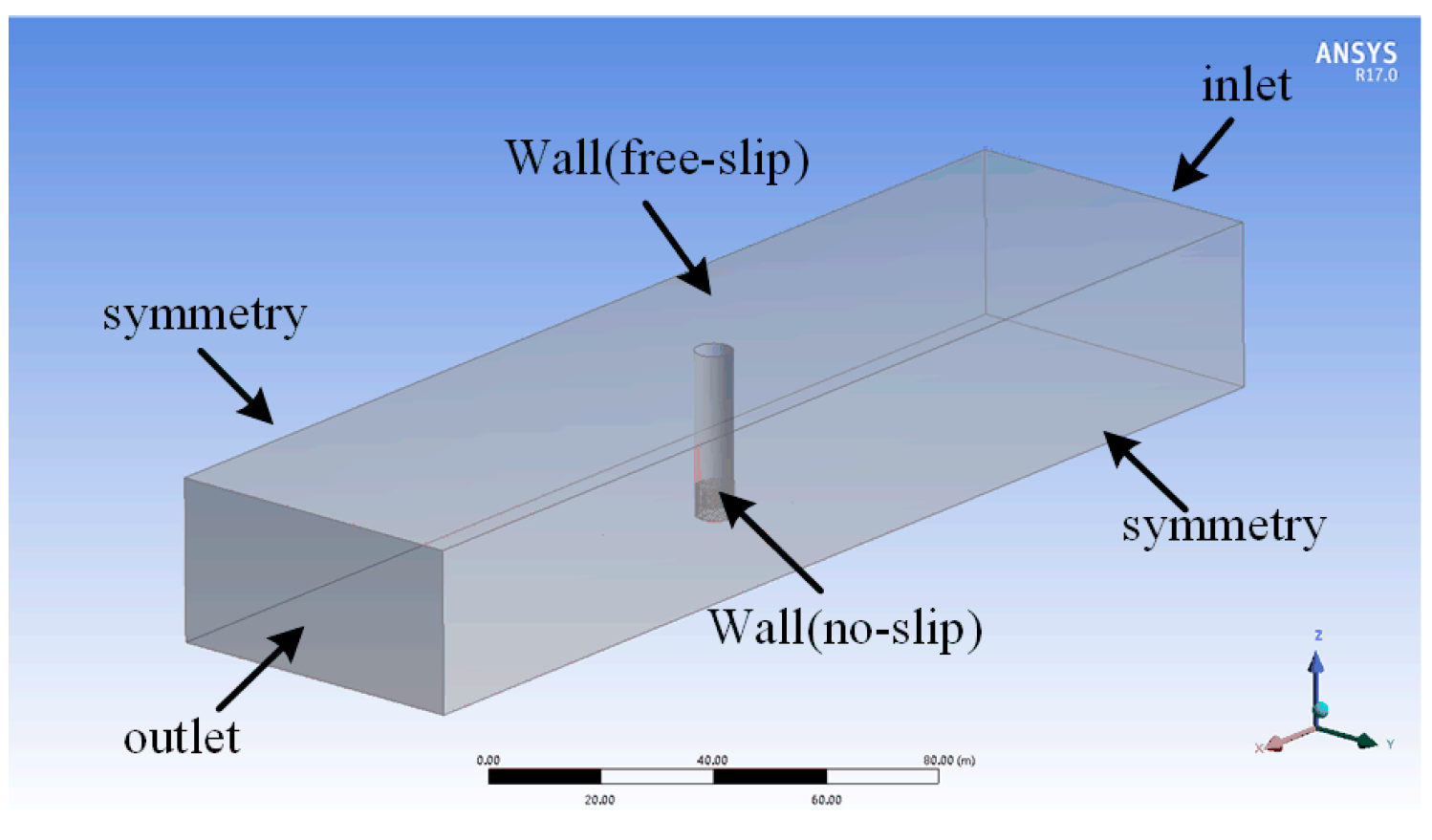
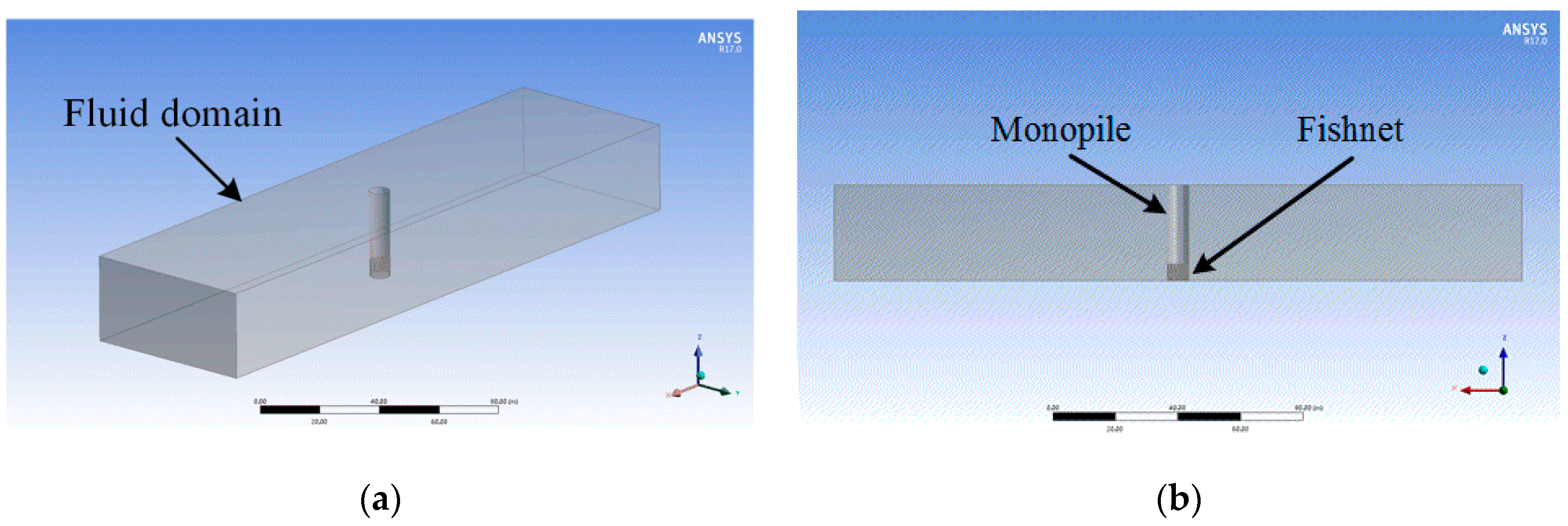
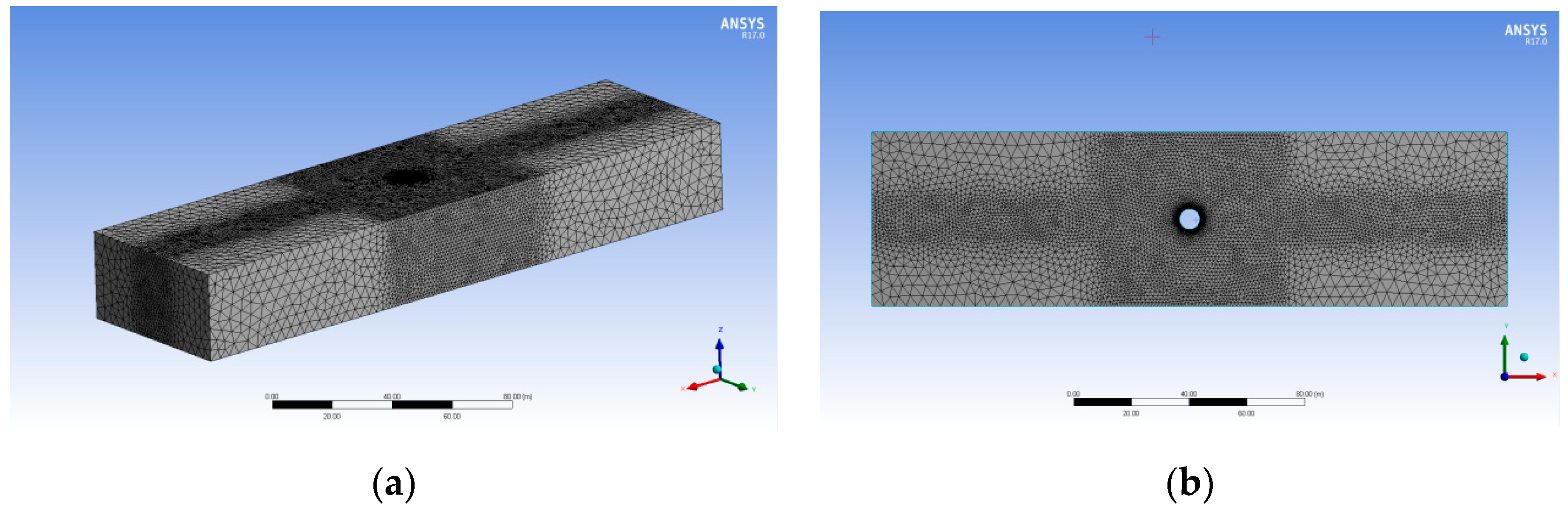
3. Development of Numerical Models

Two numerical models of the monopile foundation are developed in this section. The first model is for investigating the effectiveness of “fishnet” in erosion reduction, which is intuitively indicated by streamline, seabed surface shear stress, and eddy viscosity. The second is for optimizing the design of “fishnet” technology. As Figure 3 shows, the parameters being optimized included the size of fishnet (l), the diameter of the fishnet thread (d), and the length of the fishnet device (H).
In the numerical calculations, a monopile foundation with a diameter of 7 m was considered, which was used to support a VESTAS 8-MW offshore wind turbine. The flow speed U ¯ was assumed to satisfy the following profile [23]:
U ( z ) = { ( z 0.32   h ) 1 7 U ¯ ( 0 < z < 0.5 h ) 1.07 U ¯ ( 0.5 h < z < h ) ,
where z refers to the distance above the seabed, h indicates the water depth, and U ¯ is the depth average flow speed. The current speed profile shown in Equation (1) was used to determine the input current based on the current speed of 0.7 m/s at the height of 0.32 h above the seabed [23].
Subsequently, a numerical model was developed in ANSYS FLUENT [24] to simulate the monopile foundation of an offshore wind turbine. As shown in Figure 4, a 220-m-long, 60-m-wide, and 30-m-high fluid domain was defined. The coordinates of the bottom of the center of the pile were (0, 0, 0), and the positive direction of the X-axis was the water flow direction.
In general, more meshes in a numerical simulation generate more accurate calculation results and, correspondingly, longer calculation times. In order to obtain accurate calculation results in a shorter calculation time when the iteration time was set to 2500, the correlation between the number of meshes and the calculation results of the maximum shear stress on nearby seabed surface was calculated first. The calculation results are shown in Figure 5.
From Figure 5, it can be seen that the maximum shear stress showed a positive correlation with the number of elements and started to converge to a relatively steady value after the number of elements was larger than 14.49 million. Therefore, the fluid domain was discretized by using 14.49 million mesh elements in the subsequent numerical calculations. The specific settings are shown in Table 1.
When setting the number of elements to 14.49 million, the fluid domain in Figure 4 was meshed, and the meshing results are shown in Figure 6. In order to accurately describe the water behavior around the “monopile foundation” and its influence on the scour pit while without causing excessive calculation, fine meshes were only adopted to discretize the fluid domain in the vicinity (60 × 60 m) of the monopile and a 14-m-wide region before and after the monopile. The fluid domain in other regions was discretized using coarse meshes.
In the simulation calculation, a turbulence intensity of 5% and hydraulic diameter of 0.1 were adopted. The setting of the boundary conditions is shown in Figure 7.

4. Numerical Study

The streamline can indicate the trajectory of the water flow, the eddy viscosity can indicate the strength of the tail vortices, and the shear stress on the seabed surface can indicate the strength of scouring. Thus, the streamline, eddy viscosity, and the shear stress on the seabed obtained before and after using “fishnet” are investigated below. Data analysis was performed with the aid of Tecplot and ANSYS-CFX-CFD-Post. The obtained results are shown below.

4.1. Effectiveness Investigation

In order to investigate the effectiveness of “fishnet” in erosion reduction, the scouring behavior of tidal current around the monopile foundation before using the “fishnet” technology was investigated for comparison. Herein, Tecplot was employed to display the calculated streamlines. This is because ANSYS-CFX-CFD-Post can only display the streamlines of the whole model or a single surface, whereas Tecplot can display the local three-dimensional streamlines separately. The streamlines of the flow around the monopile are shown in Figure 8.
From Figure 8, it can clearly be seen that the direction of tidal currents changes when they reach the monopile. In detail, downflow formed in front of the monopile, particularly in the region close to the seabed where tidal currents had slower speeds. Horseshoe vortices and annular acceleration current flow can clearly be seen on the side of the monopile, and pairs of counter-rotating vortices can also be observed behind the monopile.
After installing a “fishnet”, characterized by l = 40 cm, d = 5 cm, and H = 3.5 m, on the monopile, the streamlines of the tidal currents were re-calculated. The results are shown in Figure 9.
Although it is difficult to observe the effect of the fishnets from Figure 9a, it can clearly be found from Figure 9b that small vortices were generated by the fishnets, which disturbed the original flow field and, thus, affected the downflow and the vortices around the monopile.
Although the streamlines in Figure 9 successfully indicated the working mechanism of the fishnets, they were still unable to demonstrate the effect of “fishnet” in erosion reduction. It is known that seabed erosion happens only when the shear stress on the seabed exceeds a critical value [23]. For this reason, the shear stress on the seabed around the monopile foundation was calculated before and after adopting the “fishnet” technology. The calculation results are shown in Figure 10.
From Figure 10a, it can be found that the shear stresses on both sides of the monopile were much larger than those in other areas, meaning that the left and right sides of the pile were more susceptible to erosion, and that scour pits were to be produced there first. From Figure 10b, it can be found that, after using the fishnet device, the shear stresses on both sides of the monopile were significantly reduced. Before using the “fishnet” technology, the maximum shear stress on the surface of the nearby seabed was 1.179 Pa. The maximum shear stress on the surface of the seabed decreased to 1.012 Pa after the “fishnet” technology was adopted. In other words, the maximum shear stress was reduced by 14% after using the proposed technique.
Finally, considering that eddy viscosity can be used to characterize the transport and dissipation of the energy of the vortices around the monopole [25], the eddy viscosities before and after using the fishnets were calculated. The results are shown in Figure 11.
From Figure 11, it can be seen that a pair of vortices occurred behind the monopile, which corresponded to the trajectory of the tail vortices. Before using the “fishnet” technology, the maximum eddy viscosity was 3.317 Pa. The maximum shear stress on the surface of the seabed decreased to 3.255 Pa after the “fishnet” technology was adopted. Although such a reduction in the maximum eddy viscosity was not obvious, the comparison of Figure 11a,b shows that the tail vortices were significantly suppressed by the fishnets.

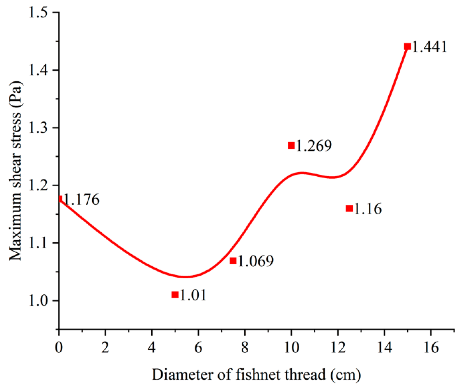
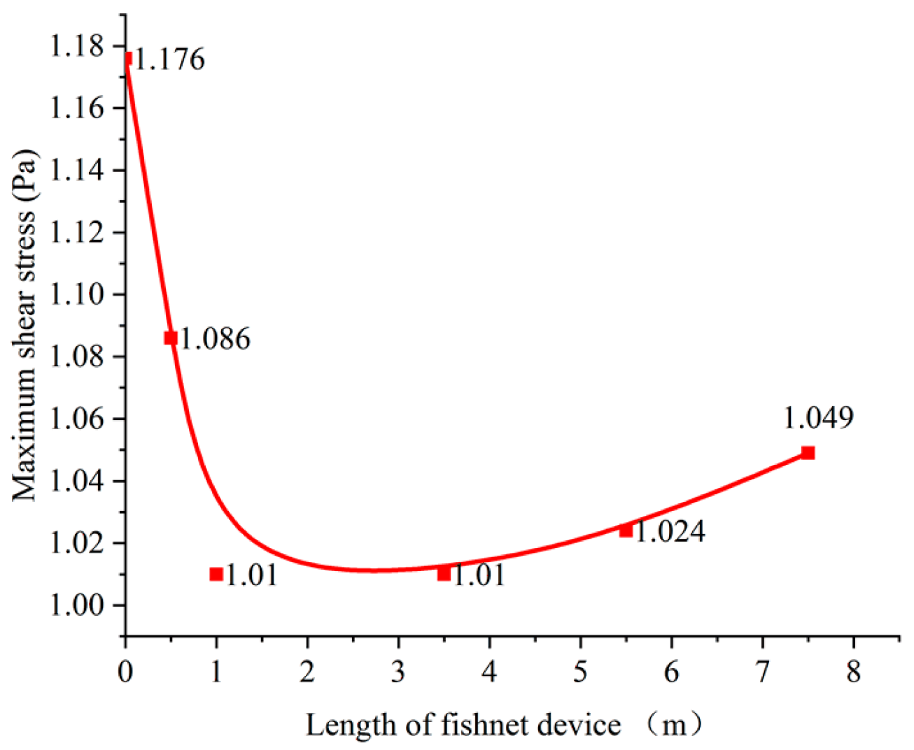
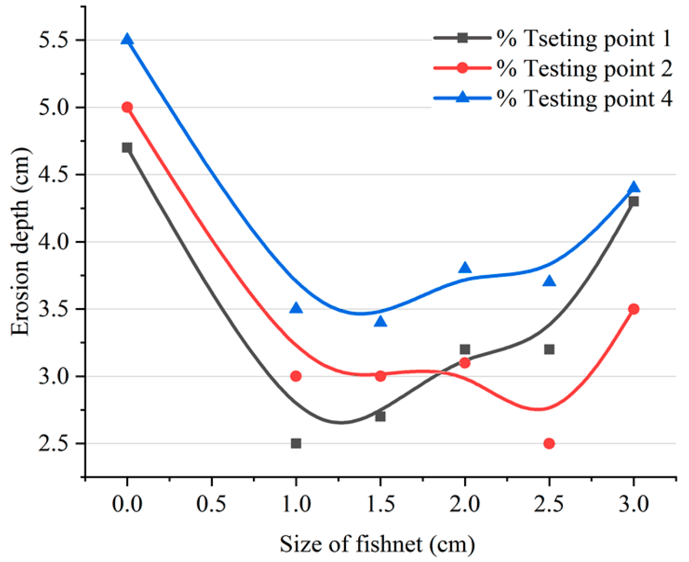
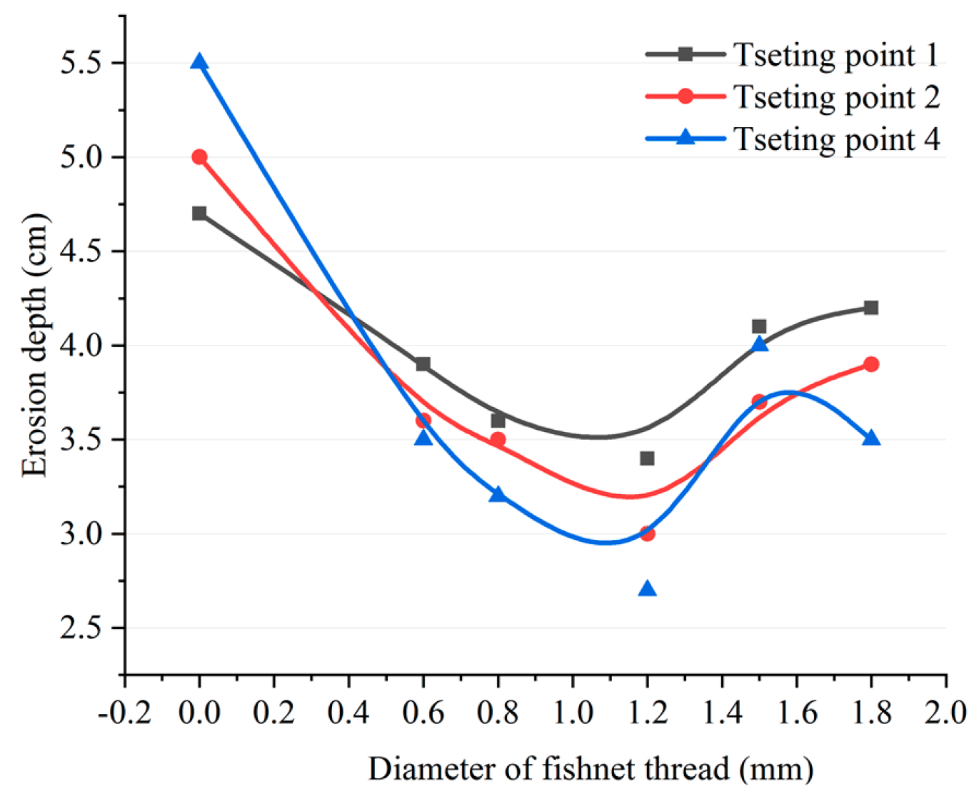
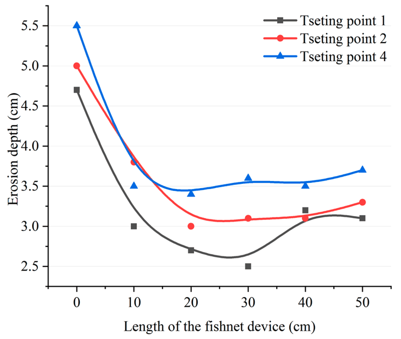
4.2. Optimization of “Fishnet” Technology

Since the size and installation of the fishnet device may significantly affect the effectiveness of the proposed technology, the erosion reduction effect when the fishnet device had different settings of l, d, and H was investigated so as to obtain an optimal design of the device. The parameters used in different scenarios are listed in Table 2. In all of these scenarios, the fishnet had a thread angle of 45°. The values of the maximum shear stress obtained in the different scenarios are shown in Figure 12. In the figure, size “0” implies that there was no fishnet on the monopile.
From Figure 12, it can be found that, before using the fishnet device, the maximum shear stress on the seabed was 1.176 Pa. After using the fishnet device, the maximum shear stress was more or less reduced. When the size of the fishnets was increased from 20 cm, the value of the maximum shear stress decreased first and reached the minimum value of 1.01 Pa when the size was 40 cm, and then increased again with the continual increase in fishnet size. In comparison to the maximum shear stress obtained before using the fishnet device, the value of 1.01 Pa obtained when the size was 40 cm implies a reduction by about 14%. Thus, it can be said that fishnet had the best protective effect when the size of the fishnets was 40 cm.
After obtaining the optimal size of fishnet, the effect of the diameter of the fishnet thread on erosion reduction was investigated, and the results are shown in Figure 13. In the calculations, the size of the fishnets was 40 cm, and the length of the fishnet device was 3.5 m. The diameters of the fishnet thread considered were 5 cm, 7.5 cm, 10 cm, 12.5 cm, and 15 cm.
From Figure 13, it can be seen that, with the increase of the diameter of the fishnet thread, the maximum shear stress on the seabed showed a generally increasing tendency. This suggests that a smaller diameter of the fishnet thread results in more scouring being mitigated. In comparison to the maximum shear stress of 1.176 Pa before using the fishnet device, the maximum shear stress dropped to 1.01 Pa when the diameter of the fishnet thread was 5 cm, which indicates a reduction of 14%.
Finally, the influence of the length of the fishnet device on erosion reduction was investigated when the size of the fishnets was 40 cm and the diameter of the fishnet thread was 5 cm. The lengths of the fishnet device being considered in the investigation were 0.5 m, 1 m, 3.5 m, 5.5 m, and 7.5 m. The calculation results obtained in different scenarios are shown in Figure 14.
From Figure 14, it can be found that, when the length of the fishnet device was increased, the value of the maximum shear stress decreased first, reached the minimum value of 1.01 Pa when the length of the device was 1 m, and then increased again with the increasing length of the fishnet device. This suggests that the optimal length was 1 m.

5. Laboratory Tests

In order to demonstrate the actual effect of the proposed technology on erosion reduction in real-life application, three experiments were conducted in the laboratory to characterize (a) the effect of the fishnet size, (b) the influence of the fishnet thread diameter, and (c) the influence of the length of fishnet device on the erosion reduction effect. The scenarios considered in the laboratory tests are listed in Table 3.

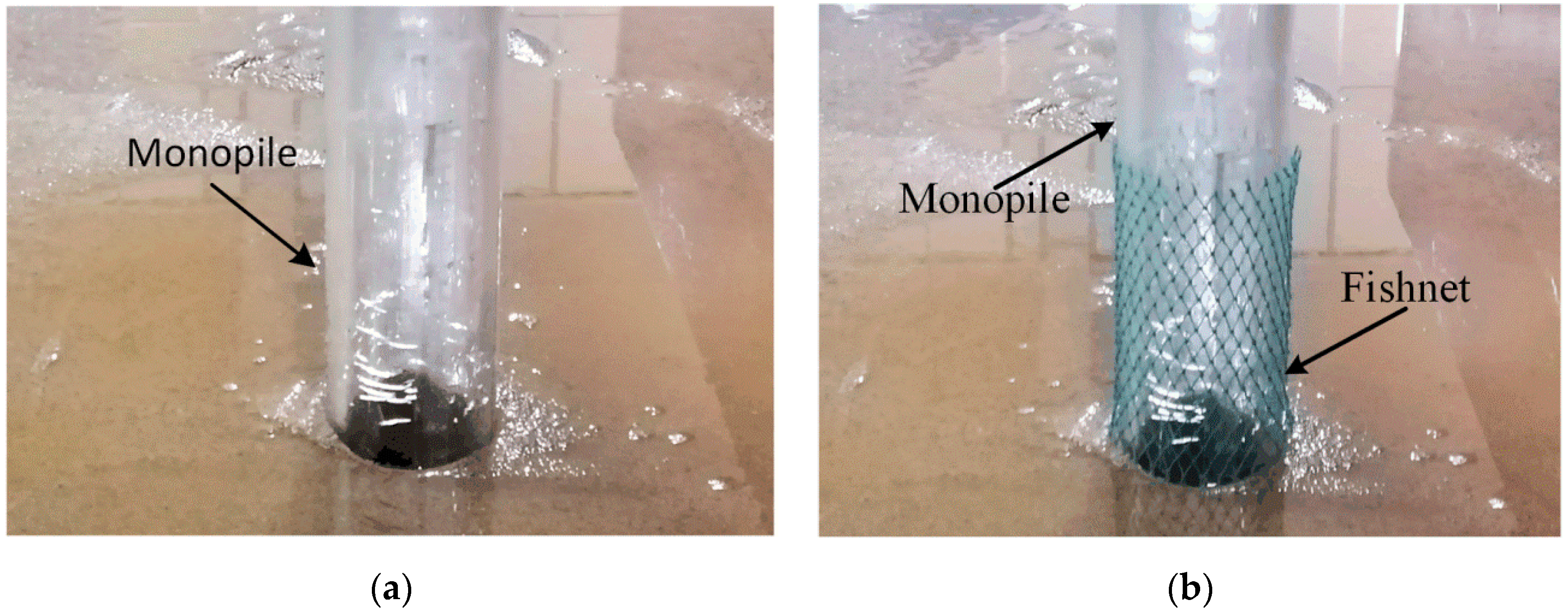
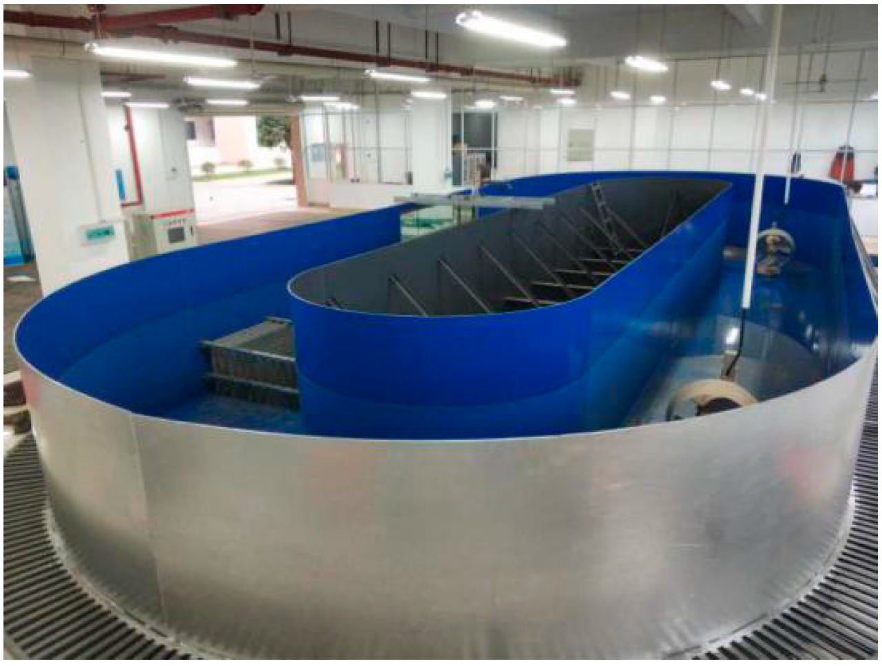
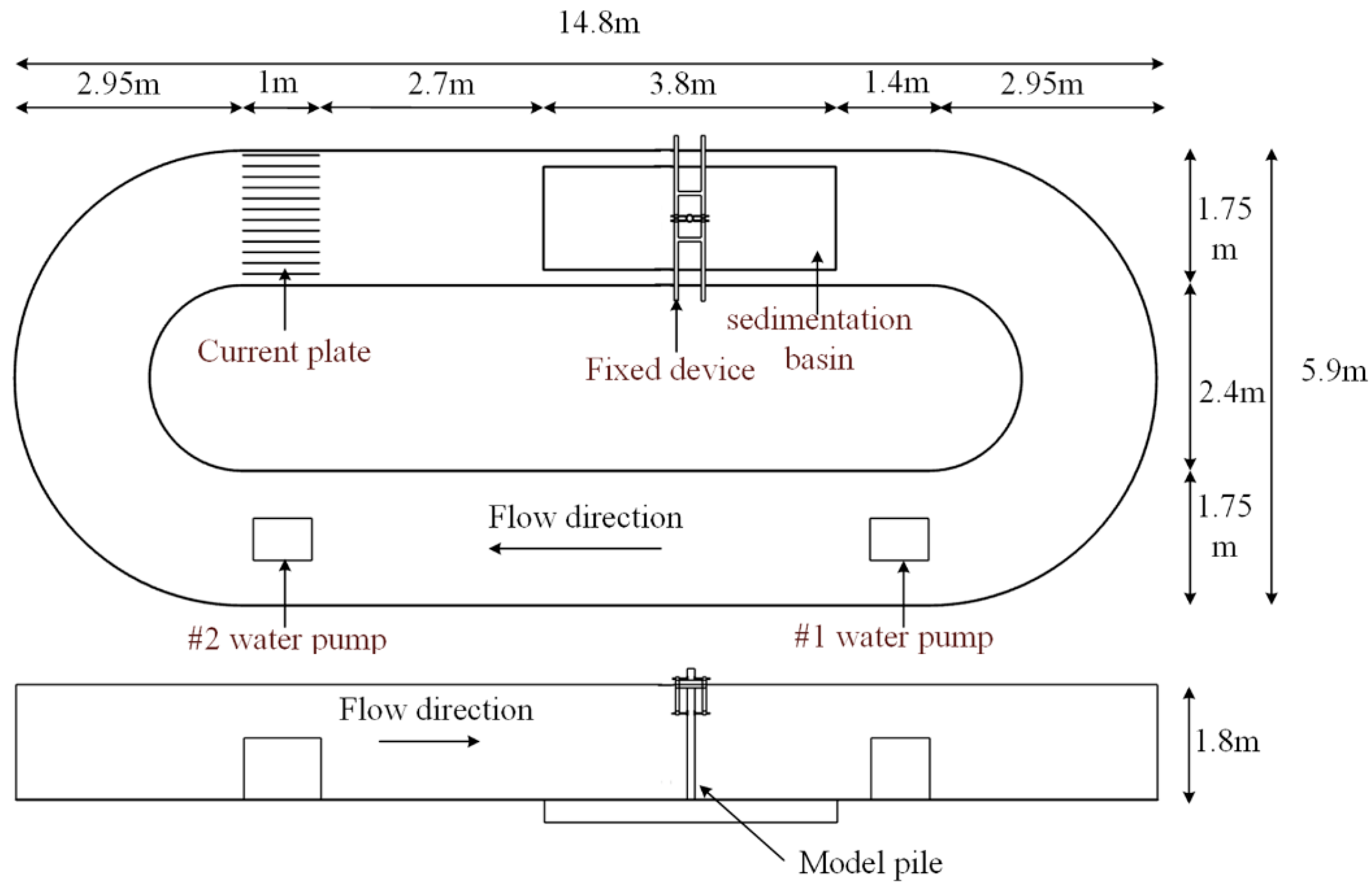
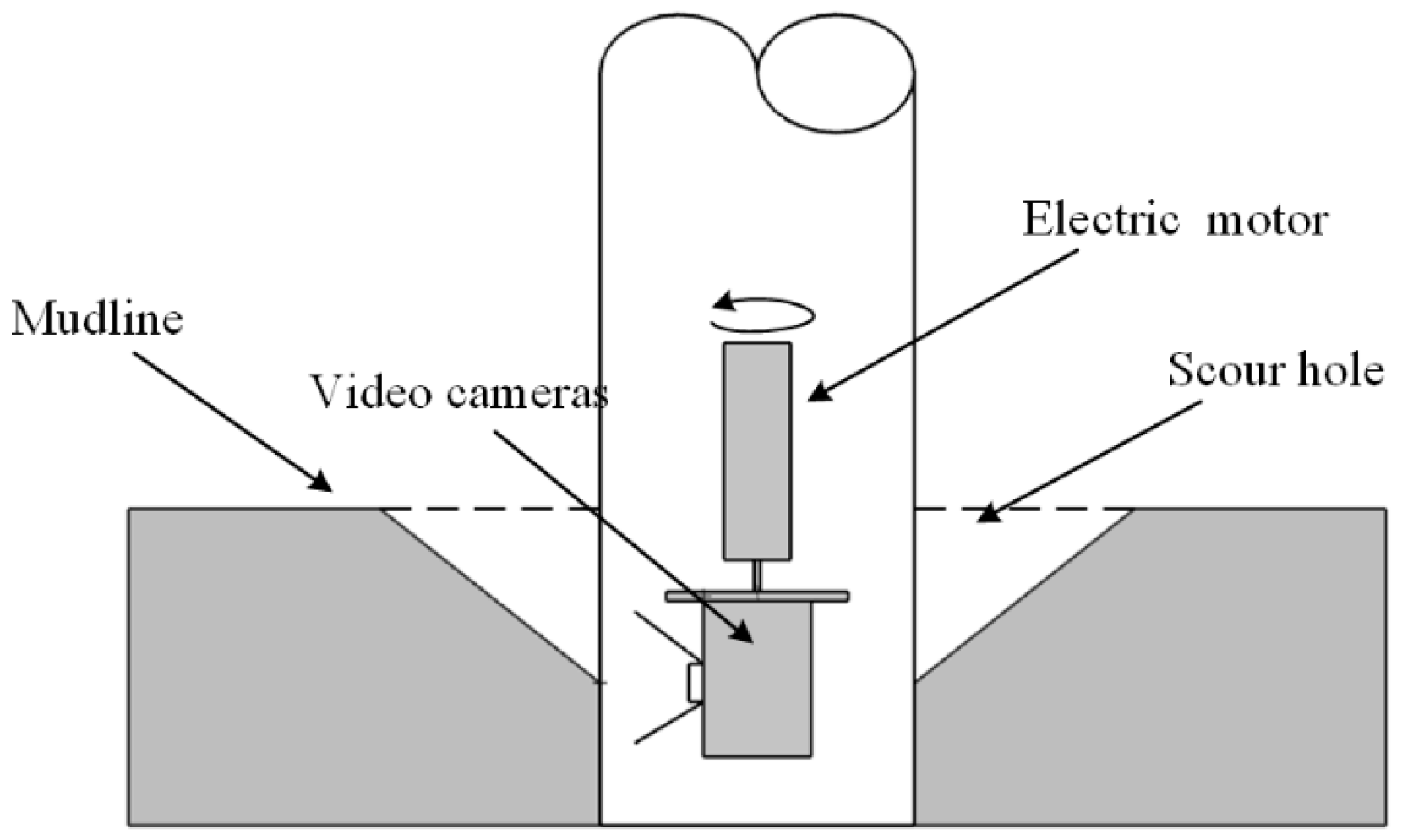
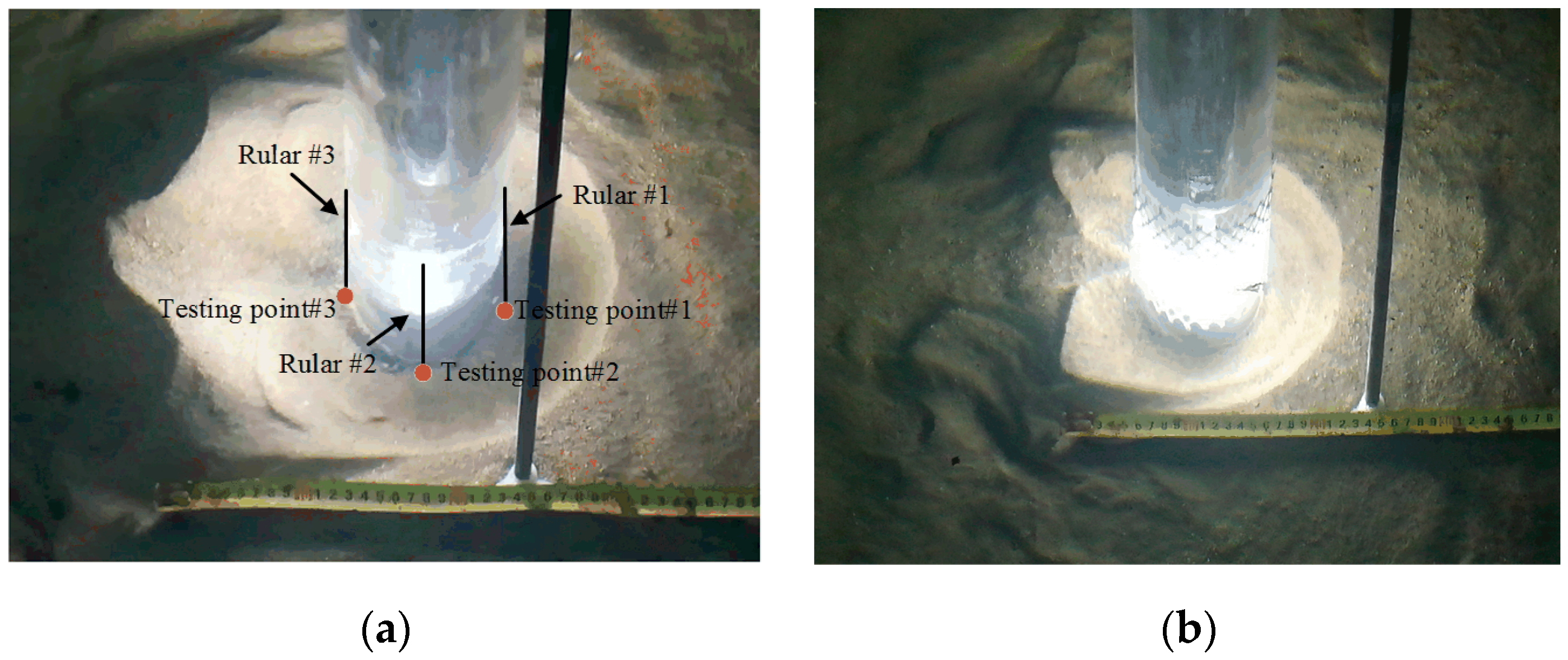
5.1. Experimental Apparatus

The experiments were performed in the tidal current tank shown in Figure 15. The tidal current tank was 14.65 m long, 5.9 m wide, and 1.8 m high. At both ends of it, the outer diameter was 5.9 m and the inner diameter was 2.4 m. On the front side of the tank, a glass window was designed for facilitating observation. The speed of the tidal current in the tank could be varied in a large range (0.1 m/s to 2.0 m/s) by controlling the rotating speed of the two propulsion systems installed on either side.
The sedimentation basin in the tank was built behind the observation window. It was 3.8 m long, 1.35 m wide, and 0.3 m deep. The monopile was made of plexiglass. The outer diameter of the monopile was 0.1 m, its wall thickness was 10 mm, and its height was 2 m. The monopile was placed in the center of the sedimentation basin, as shown in Figure 16. The sand in the sedimentation basin was standard river sand, and the diameter of the sand varied from 0.1 to 0.5 mm. During the experiment, the average flow rate was set to 0.22 m/s to ensure that scour pits could be produced in reasonable testing time.
A data acquisition device was specifically designed to record the depth of scour pit. As shown in Figure 17, it was composed of a camera, power supply, motor, ruler, and auxiliaries. The motor had a rated speed of 7 rpm. During data collection, the motor rotated the camera continuously so that the camera could monitor the development of scout pits in all directions.

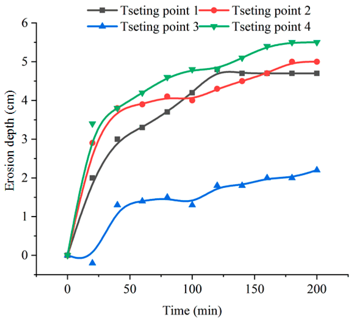
5.2. Testing Results

First of all, the erosion around the monopole before using the “fishnet” technique was investigated. After the tank was filled with 1-m-deep water, the two propulsion systems started to accelerate the water in the tank until the average flow speed in the tank reached 0.22 m/s. The depth of erosion was then measured from four directions every 20 min. All measurement results obtained within 200 min are shown in Figure 18, where testing point 1 was located in front of the monopile, testing point 3 was behind the monopile, and testing points 2 and 4 were on either side of the monopile foundation.
From Figure 18, it can be found that, with the increase in testing time, the erosion depths in all four directions generally showed an increasing trend. However, in contrast to the results measured from the front (testing point 1) and two sides (testing points 2 and 4), the depth of the scour pit behind the monopole (i.e., at testing point 3) developed much more slowly. This was attributed to the role of the counter-rotating vortices behind the monopile (see Figure 8). Among the measurement results in the four directions, the scour pit developed most rapidly on both sides of the monopole. The largest shear stresses that occurred at these two specific locations could account for this phenomenon. However, it was interestingly found that the development of the erosion depths even at these two locations also showed more or less a difference in trend, the presence of which should be related to the asymmetric vortices on both sides of the monopole (see Figure 10a).
Then, the above tests were repeated after applying a 20-cm-long fishnet device, of which the mesh size was 1.5 cm and the diameter of the fishnet thread was 1.8 mm, to the monopole. After the test went on for 180 min, the erosion depths at testing points 1, 2, and 4 were measured. The measurement results are listed in Table 4, in which the corresponding erosion depths measured before using the “fishnet” technology are also listed for comparison.
From Table 4, it can be seen that, after using the fishnet device, the scouring depths measured at all three testing points decreased to different extents. In particular, the erosion depth measured at testing point 4 decreased most from 5.5 cm to 3.5 cm, and the corresponding reduction rate reached up to 36.36%. When considering the reduction in erosion depth in all three directions, the average reduction was about 23%. To facilitate understanding, the erosion results observed when the testing time was 180 min before and after using the fishnet device are shown in Figure 19.
From Figure 19, it can clearly be seen that, after the fishnet device was installed, the erosion was significantly constrained not only in terms of erosion depth but also in terms of the size of the area being eroded. In the meantime, it was found that, despite the application of the fishnet device, the erosion depths in front and on both sides of the monopile were always much larger than the erosion depth behind the monopile. This was consistent with the results shown in Figure 18.
Subsequently, the optimal design of the fishnet device was also investigated in the laboratory tests. As in Section 4.2, the influences of the size of the fishnet l, the diameter of the fishnet thread d, and the length of the fishnet device H on seabed erosion were investigated in the subsequent tests.
Firstly, an experiment was performed to characterize the influence of the fishnet size on erosion depth. In the experiments, the water in the tank was still 1 m deep, and the average water flow rate was still kept at 0.22 m/s. When the fishnet device was 20 cm long, the diameter of the fishnet thread was 1.2 mm, and the sizes of the fishnets were 1 cm, 1.5 cm, 2 cm, 2.5 cm, and 3 cm, the erosion depths at testing points 1, 2, and 4 were measured. The measurement results that were recorded in different scenarios when the testing time was 180 min are shown in Figure 20.
In principle, the smallest erosion depth indicates the optimal size of the fishnet. However, from Figure 20, it was interestingly found that the smallest erosion depth in different directions was observed at different sizes of the fishnet. In particular, the erosion depth at testing point 2 showed an extremely low value when the size of the fishnet was 2.5 cm due to either measurement error or other uncertainties in the laboratory test. Such an outlier disturbed the judgment of the optimal size of the fishnet. Despite this, it can still be seen that a generally satisfactory erosion reduction effect could be achieved when the size of the fishnet was 1.0 (based on point 1) or 1.5 cm (based on point 4).
Secondly, the optimal diameter of the fishnet thread was investigated. In the experiments, the size of the fishnet was 1.5 cm, the length of the fishnet device was still 20 cm, the diameters of the fishnet thread were 0.6 mm, 0.8 mm, 1.2 mm, 1.5 mm, and 1.8 mm. The erosion depths that were measured in different scenarios when the testing time was 180 min are shown in Figure 21.
From Figure 21, it can clearly be seen that the smallest erosion depth was obtained in all three directions when the diameter of the fishnet thread was 1.2 mm. Thus, it can be said that 1.2 mm should be the optimal diameter of the fishnet thread.
Finally, the optimal length of the fishnet device was investigated in the laboratory. In the experiments, the size of the fishnet was selected to be 1.5 cm, and the diameter of the fishnet thread was 1.2 mm, while the lengths of the fishnet device were selected to be 10 cm, 20 cm, 30 cm, 40 cm, and 50 cm. The erosion depths that were measured in different scenarios when the testing time was 180 min are shown in Figure 22.
From Figure 22, it can be seen that changes in the length of the fishnet device minimally affected the erosion depth on both sides of the monopile, as its efficiency was maintained at about 38.2%. However, the earlier numerical study disclosed that the erosion reduction efficiency of the proposed “fishnet” technology was only about 14%. On the other hand, according to Reference [21], an efficiency of about 46.3% could be observed from the spiral technology when the spiral angle was 15°. Obviously, there is no consensus on the efficiency of this kind of technology. The difference may be related to many variables in both numerical calculations and laboratory tests. However, despite these differences, it can be concluded that the “fishnet” technology studied above can indeed reduce scouring, and its contribution to erosion reduction can be further improved by performing parameter optimization.

6. Conclusions

Scouring causes seabed erosion in the vicinity of large-diameter monopile foundations, resulting in safety issues for offshore wind turbines. In order to solve this problem, this paper proposed a new type of anti-scour device, named “fishnet” technology. From the research described above, the following conclusions can be drawn:
(1)
The fishnet is low in cost and convenient to install at the site; for example, it can be readily tied to the monopile foundation by a frogman. This means that the maintenance cost of the monopile foundation for offshore wind turbines can be significantly reduced after using such a technique.
(2)
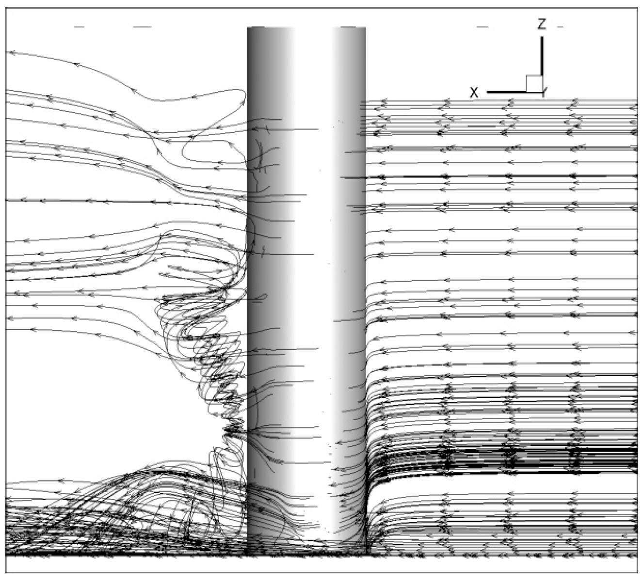
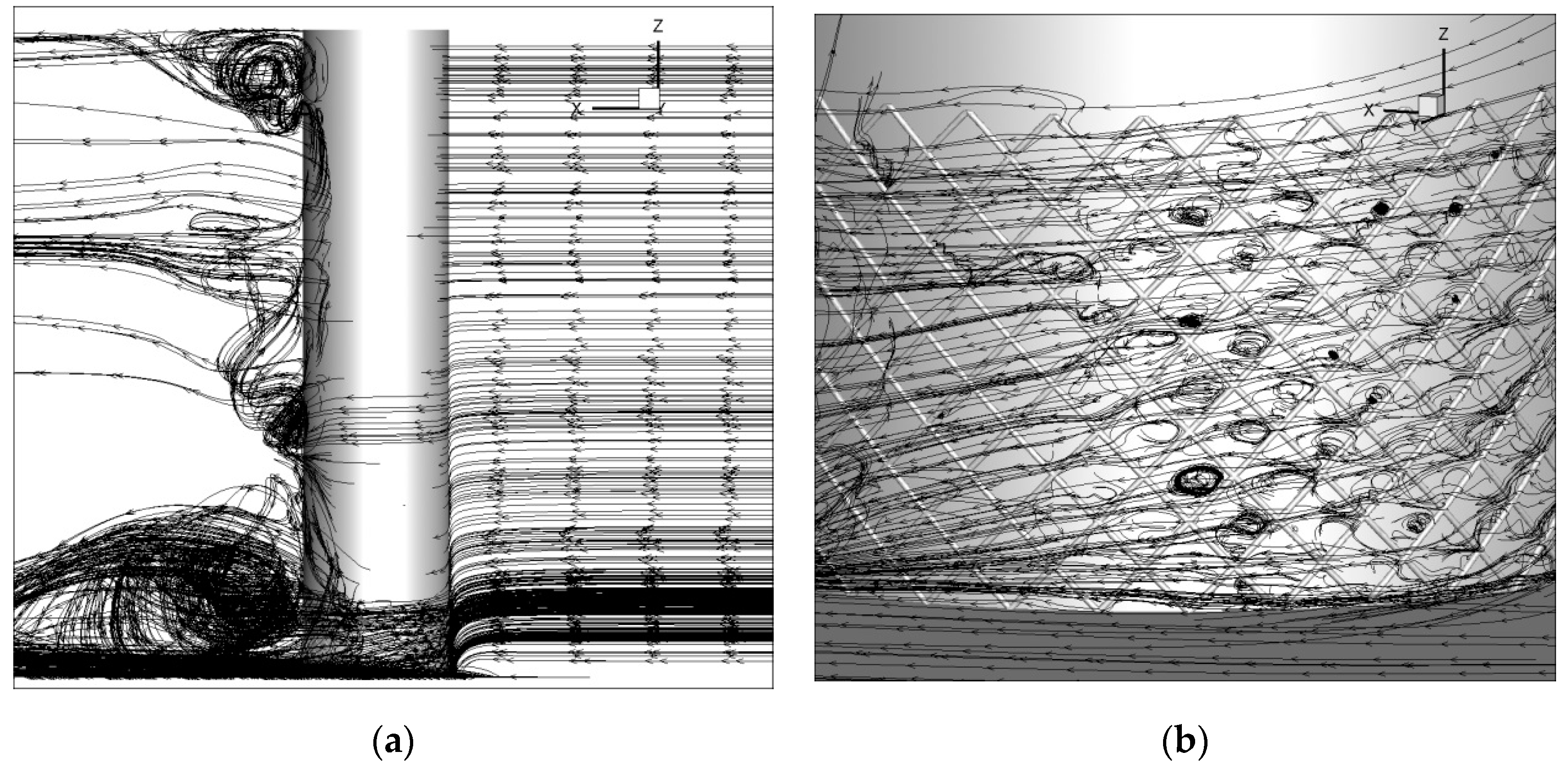
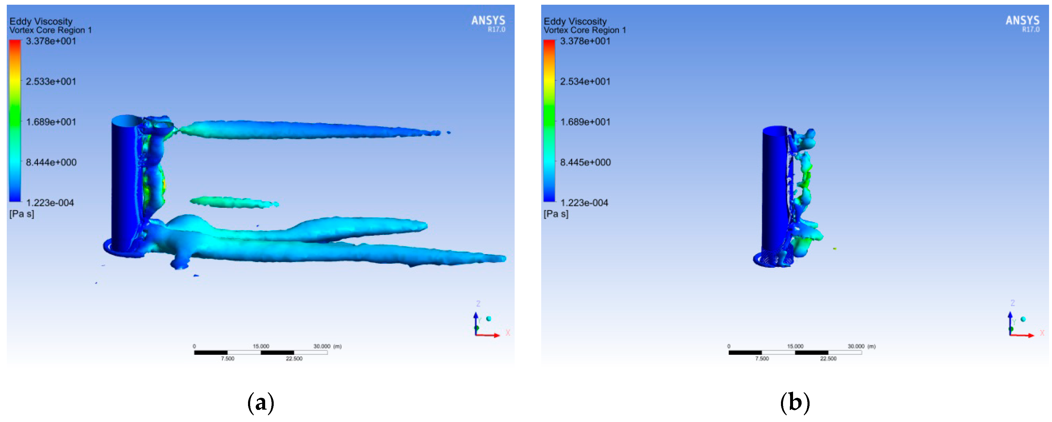
After using the fishnet device, the local streamlines near fishnets are significantly disturbed, which consumes the energy of the downflows and the vortices around the monopile foundation.
(3)
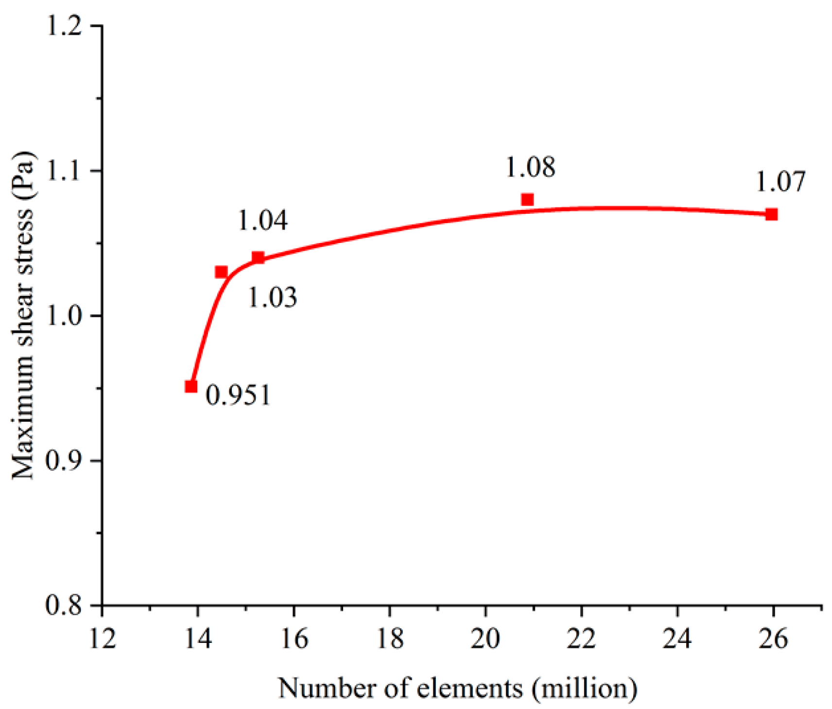
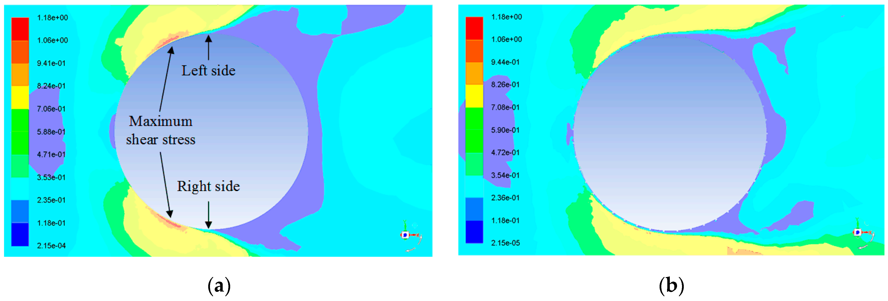
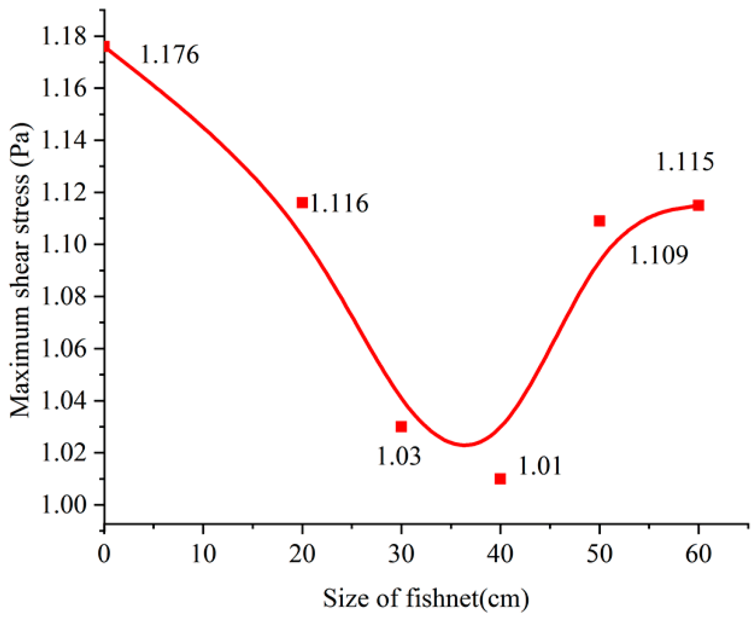
Both numerical studies and laboratory tests showed that the “fishnet” technology can indeed reduce the scouring, and its contribution to erosion reduction can be further improved by performing parameter optimization. The numerical study showed that the maximum shear stress on the seabed in the vicinity of the monopile foundation could be reduced by about 14%, while the laboratory experiment showed that the largest erosion depth around the monopile foundation could be reduced by about 38%.
The research reported above demonstrated the potential of the proposed “fishnet” technology in reducing the seabed erosion around the monopile foundation of offshore wind turbines. Moreover, it proved that the effect of the “fishnet” technology can be further improved by optimizing the design of the fishnet device. In this work, the influences of the fishnet size, the diameter of fishnet thread, and the length of the fishnet device were considered. However, the effect of the spiral angle of the fishnet thread on erosion reduction was not investigated. Next, the proposed “fishnet” technology will be further improved by optimizing the spiral angle of the fishnet thread. The relevant research will be reported in a separate paper.

Author Contributions

Conceptualization, K.W. and W.Y.; methodology, B.Y. and W.Y.; software, B.Y. and T.L.; validation, B.Y. and T.L.; formal analysis, B.Y.; investigation, K.W.; resources, L.N.; writing—original draft preparation, B.Y.; writing—review and editing, W.Y. and B.Q.; visualization, B.Q.; supervision, K.W. and W.Y.; project administration, K.W.; funding acquisition, K.W.

Funding

This research was funded by the National Natural Science Foundation of China (11772126), the Hunan Provincial Natural Science Foundation of China (2017JJ4017), and the UK EPSRC fund (EP/R021503/1).

Conflicts of Interest

The authors declare no conflicts of interest.

References

  1. MarStrach-Sonsalla, M.; Muskulus, M. Prospects of Floating Wind Energy. Int. J. Offshore Polar Eng. 2016, 26, 81–87. [Google Scholar] [CrossRef]
  2. Anastasia, I.; Andrew, A.; Feargal, B. Parametric CAPEX, OPEX, and LCOE expressions for offshore wind farms based on global deployment parameters. Energy Sources Part B Econ. Plan. Policy 2018, 13, 281–290. [Google Scholar]
  3. Yang, W.; Tian, W. Concept Research of a Countermeasure Device for Preventing Scour around the Monopile Foundations of Offshore Wind Turbines. Energies 2018, 11, 2593. [Google Scholar] [CrossRef]
  4. Chiew, Y.M. Mechanics of riprap failure at bridge piers. J. Hydraul. Eng. 1995, 121, 635–643. [Google Scholar] [CrossRef]
  5. Larsen, T.J.; Madsen, H.A.; Larsen, G.C.; Hansen, K.S. Validation of the dynamic wake meander model for loads and power production in the Egmond aan Zee wind farm. Wind Energy 2013, 16, 605–624. [Google Scholar] [CrossRef]
  6. Tafarojnoruz, A.; Gaudio, R.; Calomino, F. Evaluation of flow-altering countermeasures against bridge pier scour. J. Hydraul. Eng. 2012, 138, 297–305. [Google Scholar] [CrossRef]
  7. Mostafa, Y.E. Effect of local and global scour on lateral response of single piles in different soil conditions. Engineering 2012, 4, 297–306. [Google Scholar] [CrossRef]
  8. Froehlich, D.C. Protecting bridge piers with loose rock riprap. J. Appl. Water Eng. Res. 2013, 1, 39–57. [Google Scholar] [CrossRef]
  9. Melville, B.W.; Hadfield, A.C. Use of sacrificial piles as pier scour countermeasures. J. Hydraul. Eng. 1999, 125, 1221–1224. [Google Scholar] [CrossRef]
  10. Moreno, M.; Birjukova, O.; Grimaldi, C.; Gaudio, R.; Cardoso, A.H. Experimental study on local scouring at pile-supported piers. J. Acta Geophys. 2017, 65, 1–11. [Google Scholar] [CrossRef]
  11. Zarrati, A.R.; Gholami, H.; Mashahir, M.B. Application of collar to control scouring around rectangular bridge piers. J. Hydraul. Res. 2004, 42, 97–103. [Google Scholar] [CrossRef]
  12. Brand, M.W.; Dewoolkar, M.M.; Rizzo, D.M. Use of sacrificial embankments to minimize bridge damage from scour during extreme flow events. Nat. Hazards 2017, 87, 1469–1487. [Google Scholar] [CrossRef]
  13. Haque, M.A.; Rahman, M.M.; Islam, G.M.T.; Huassin, M.A. Scour mitigation at bridge piers using sacrificial piles. Int. J. Sediment Res. 2007, 22, 49–59. [Google Scholar]
  14. Khassaf, S.I.; Obied, N.A. Experimental Study: Bridge Pier Protection against Local Scour Using Guide Panels; IOP Conference Series: Materials Science and Engineering; IOP Publishing: Bristol, UK, 2018; Volume 433, p. 012006. [Google Scholar]
  15. Kumar, V.; Raju, K.G.R.; Vittal, N. Reduction of local scour around bridge piers using slots and collars. J. Hydraul. Eng. 1999, 125, 1302–1305. [Google Scholar] [CrossRef]
  16. Vijayasree, B.A.; Eldho, T.I.; Mazumder, B.S.; Viswanadham, B.V.S. Effectiveness of combinations of raft foundation with aprons as a protection measure against bridge pier scour. Sādhanā 2018, 43, 21. [Google Scholar] [CrossRef]
  17. Whitehouse, R.J.S.; Brown, A.; Audenaert, S.; Bolle, A.; de Schoesitter, P.; Haerens, P.; Baelus, L.; Troch, P.A.; das Neves, L.; Ferradosa, T.; et al. Optimising scour protection stability at offshore foundations. In Proceeding of the 7th International Conference on Scour and Erosion, Perth, Australia, 2–4 December 2014; pp. 2–4. [Google Scholar]
  18. Adivi, E.G.; Bajestan, M.S.; Kermannezhad, J. Riprap sizing for scour protection at river confluence. J. Hydraul. Struct. 2016, 2, 1–11. [Google Scholar]
  19. Lim, F.H.; Chiew, Y.M. Parametric study of riprap failure around bridge piers. J. Hydraul. Res. 2001, 39, 61–72. [Google Scholar] [CrossRef]
  20. Grüne, J.; Sparboom, U.; Schmidt-Koppenhagen, R.; Wang, Z.; Oumeraci, H. Stability tests of geotextile sand containers for monopile scour protection. In Coastal Engineering 2006: Proceedings of the 30th International Conference (In Volumes 5); World Scientific Publishing Co. Pte Ltd.: Singapore, 2007; pp. 5093–5105. [Google Scholar]
  21. Dey, S.; Sumer, B.M.; Fredsøe, J. Control of scour at vertical circular piles under waves and current. J. Hydraul. Eng. 2006, 132, 270–279. [Google Scholar] [CrossRef]
  22. Tafarojnoruz, A.; Gaudio, R.; Dey, S. Flow-altering countermeasures against scour at bridge piers: A review. J. Hydraul. Res. 2010, 48, 441–452. [Google Scholar] [CrossRef]
  23. Soulsby, R. Dynamics of Marine Sands: A Manual for Practical Applications; Thomas Telford: London, UK, 1997. [Google Scholar]
  24. Ansys-Fluent Theory Guide. Available online: 6Hhttps://www.pdfdrive.com/ansys-fluent-theory-guide-d7803205.html (accessed on 2 July 2019).
  25. Hunt, J.C.R.; Wray, A.A.; Moin, P. Eddies, streams, and convergence zones in turbulent flows. In Proceedings of the 1988 Summer Program, NASA Ames, Stanford, CA, USA, 27 June–22 July 1988. [Google Scholar]
Figure 1. Helical strakes for controlling vortex-induced vibration.
Applsci 09 05023 g001
Figure 2. “Fishnet” technology: (a) before using the fishnet; (b) after using the fishnet.
Applsci 09 05023 g002
Figure 3. A numerical model of the monopile: (a) main view; (b) geometries of the fishnet.
Applsci 09 05023 g003
Figure 4. Fluid domain in the numerical model: (a) isometric view; (b) rearview.
Applsci 09 05023 g004
Figure 5. Effect of the number of mesh elements on the Fluent 17.0 calculation results.
Applsci 09 05023 g005
Figure 6. An example of the meshing results: (a) isometric view; (b) top view.
Applsci 09 05023 g006
Figure 7. Boundary conditions.
Applsci 09 05023 g007
Figure 8. Streamlines of tidal current when passing the monopile foundation.
Applsci 09 05023 g008
Figure 9. Streamlines after using the fishnet: (a) side view; (b) details of the flow in front of the monopile.
Applsci 09 05023 g009
Figure 10. Shear stress on the surface of the seabed: (a) before using fishnet; (b) after using fishnet.
Applsci 09 05023 g010
Figure 11. Eddy viscosities: (a) before using the fishnet device; (b) after using the fishnet device.
Applsci 09 05023 g011
Figure 12. Influence of the fishnet size on the maximum shear stress on the surface of the seabed.
Applsci 09 05023 g012
Figure 13. Influence of the fishnet thread diameter on the maximum shear stress on the surface of the seabed.
Applsci 09 05023 g013
Figure 14. Influence of the length of the fishnet device on the maximum shear stress.
Applsci 09 05023 g014
Figure 15. Tidal current tank used for verification test.
Applsci 09 05023 g015
Figure 16. Schematic diagrams of the tidal current tank in both sectional and plan views.
Applsci 09 05023 g016
Figure 17. Schematic diagram for monitoring the effect of the scour around the foundation.
Applsci 09 05023 g017
Figure 18. The development of scouring effect versus time at different positions before using fishnet.
Applsci 09 05023 g018
Figure 19. Scour pit: (a) before using the fishnet device; (b) after using the fishnet device.
Applsci 09 05023 g019
Figure 20. Erosion depth when fishnet had different sizes.
Applsci 09 05023 g020
Figure 21. Erosion depth when fishnet thread had different diameters.
Applsci 09 05023 g021
Figure 22. Erosion depth when the fishnet device had different lengths.
Applsci 09 05023 g022
Table 1. Settings for meshing the fluid domain of interest.
ParameterSetting
Size functionCurvature
Initial size seedActive assembly
SmoothingMedium
TransitionSlow
Span angle centerFine
Curvature normal angle12°
Min size0.02 m
Max face size4 m
Max Tet size4 m
Growth rateDefault (1.20)
Use automatic inflationProgram controlled
Inflation optionFirst aspect ratio
Fir aspect ratio5
Maximum layers5
Triangle surface mesherProgram controlled
Topology checkingYes
Pinch toleranceDefault (4.5 × 10⁻³ m)
Table 2. Scenarios considered in simulation calculations.
Size of FishnetDiameter of Fishnet ThreadLength of Fishnet Device
l (cm)d (cm)H (m)
Without fishnet----------------------
205.00.5
307.51.0
4010.03.5
5012.55.0
6015.07.5
Table 3. Scenarios considered in the laboratory tests.
Size of FishnetDiameter of Fishnet ThreadPosition of Fishnet above the Seabed
l d H
Without fishnet----------------------
1 cm0.6 mm10 cm
1.5 cm0.8 mm20 cm
2 cm1.2 mm30 cm
2.5 cm1.5 mm40 cm
3 cm1.8 mm50 cm
Table 4. Effectiveness investigation results of the “fishnet” technology.
Testing PointErosion Depth before Using “Fishnet” (cm)Erosion Depth after Using “Fishnet” (cm)Reduction Rate (%)
14.74.210.64
25.03.922.00
45.53.536.36

