Article

Enhanced FANO Structure Based on Tip-Field-Enhancement Theory

1
Terahertz Science Cooperative Innovation Center, School of Electronic Science and Engineering, University of Electronic Science and Technology of China, Chengdu 611731, China
2
School of Electronic Engineering and Computer Science, Queen Mary, University of London, London E1 4NS, UK
3
National Key Laboratory of Application Specific Integrated Circuit, Hebei Semiconductor Research Institute, Shijiazhuang 050051, China
*
Authors to whom correspondence should be addressed.
Tianchi Zhou and Bo Zhang are co-first authors.
Appl. Sci. 2019, 9(23), 5009; https://doi.org/10.3390/app9235009
Submission received: 11 October 2019 / Revised: 17 November 2019 / Accepted: 18 November 2019 / Published: 21 November 2019
(This article belongs to the Special Issue Photonic Crystals for Electromagnetic Applications)

Abstract

:
High-Q metasurfaces have attracted much interest owing to their potential application in biological sensors. FANO is a type of high-Q factor metasurface. However, it is difficult to achieve large resonant intensity and a high-Q factor at the same time. In this paper, by sharpening the tips of the asymmetrical split-ring FANO structure and letting more charges stack at the tips to enhance tip coupling, the Q factor was significantly improved without sacrificing too much resonant intensity. Simulation results showed that the Q factor increased up to 2.4 times, while the resonant intensity stayed higher than 20 dB, and the experiment results agreed with the simulations. This indicated that the tip-field-enhancement theory can be applied in time-harmonic electromagnetic-fields, and the method proposed here can be used to increase the sensitivity and accuracy of microfluidic sensors. Additionally, other types of research, such as on antenna design, could benefit from this theory.

1. Introduction

Metasurfaces are 2D arrays that consist of a series of elements that can be used, for example as filters, modulators, sensors, and vortex-beam generators [1,2,3,4,5,6,7,8,9,10,11,12,13]. Nevertheless, a very-high-Q factor usually cannot be achieved on a metasurface with planar structures.
A high-Q factor is essential to many devices since it leads to better frequency selectivity, which can enable the detection of narrow-band signals from noise. A high-Q resonator can also be used as a frequency probe. The complex biological molecules of different structures usually have different resonant frequencies, and using sharp frequency probes, one can distinguish them from one another. Such a method is very useful, especially when the resonant frequencies of the two different molecules to be tested are close to each other.
Unlike dipole structures and LC resonant structures that have low-Q factors, FANO is a group of metasurfaces that can reach high-Q resonances, usually based on asymmetric structures [14,15,16]. For example, if a metal ring is cut asymmetrically, it makes up a FANO structure [14,17,18]. Besides two individual broad-band dipole resonances, a narrow-band FANO resonance is introduced between the frequencies of the former ones. The upper and lower arcs act as two individual dipole resonators. The gap between the arcs induces coupling into the structure thus the resonances could interfere with each other [19,20]. The two dipole resonances will affect each other remarkably provided that the coupling is strong enough. At FANO resonant frequency, the current flowing at the two arcs will shift from out-phase to in-phase. Moreover, the current will increase a lot at FANO resonant frequency compared with other ones with frequencies nearby. Out-phased current will counteract and make THz wave propagate unencumbered through the chip. However, in-phase current will strengthen themselves and neutralize the stimulation, thus caused transmission zero point. Furthermore, stronger coupling will cause the current phase shift in a narrower band, which means strong coupling forms high Q resonance. FANO resonance can also be introduced by using many other asymmetric structures can also introduce FANO resonance. Rectangular asymmetrically split rings can also perform this task [21]. Not only the coupling inside the ring but also the one between the asymmetric rings can make up FANO structures and lead to high-Q resonances [22]. The asymmetric structures lead to asymmetric charge distribution and excite unbalanced current mode, causing strong destructive interference with input THz wave, resulting in FANO resonances [19,20]. The impact of conductivity on metal FANO structures is studied [23]. Materials other than metal that can be used in FANO structures are proposed, including a nanoscale subwavelength dielectric resonator array [24], an asymmetric ferroelectric wire pair [25] in order to achieve a high-Q factor that can expend the slope of application for all-dielectric meta resonators. Active FANO structures working in the terahertz and the infrared band were also investigated, allowing for a tunable and high-Q factor [26,27]. FANO structures of different shapes have also attracted much attention [28,29]. Besides high-Q resonance, other features, such as low loss, were also proposed by scholars using asymmetric split-ring resonators in the microwave band [22].
However, most of the methods used to increase the Q factor are complex or the structures are difficult to fabricate. Moreover, it is difficult for FANO structures to achieve high-Q factor and high resonance intensity at the same time, which may be useful for sensors. A high-Q FANO structure [17] was proposed reaching up to 50 Q factor, but its resonance intensity is less than 6 dB, which limits its application in microfluidic sensors, because the resonance-frequency drift caused by liquid flow beneath the structure does not lead to a huge transmission difference in a given frequency due to its low resonance intensity.
High-Q resonance is introduced by the coupling of asymmetric structures [22], resulting in electric charges accumulate at the border. If there are more charges accumulated at the border, the resonance would be enhanced, which means that it can achieve a higher-Q factor or higher resonance intensity. In static electric-field theory, charges gather at the sharpest points. It is possible that if we sharpen the coupling zones of the structure, FANO resonance could be enhanced.
In this paper, an enhanced-FANO structure with sharpened tips is discussed, and a positive correlation between sharp structures and a high-Q factor can be observed. The Q factor of the structure could be considerably increased by simply sharpening the coupling tips in an asymmetric split-ring FANO structure while keeping resonance intensity above a reasonable level. The 2D metallic patterns are also easy to fabricate. Therefore, this can be applied to microfluidic chips to increase its sensitivity on particle detection.

2. Simulations

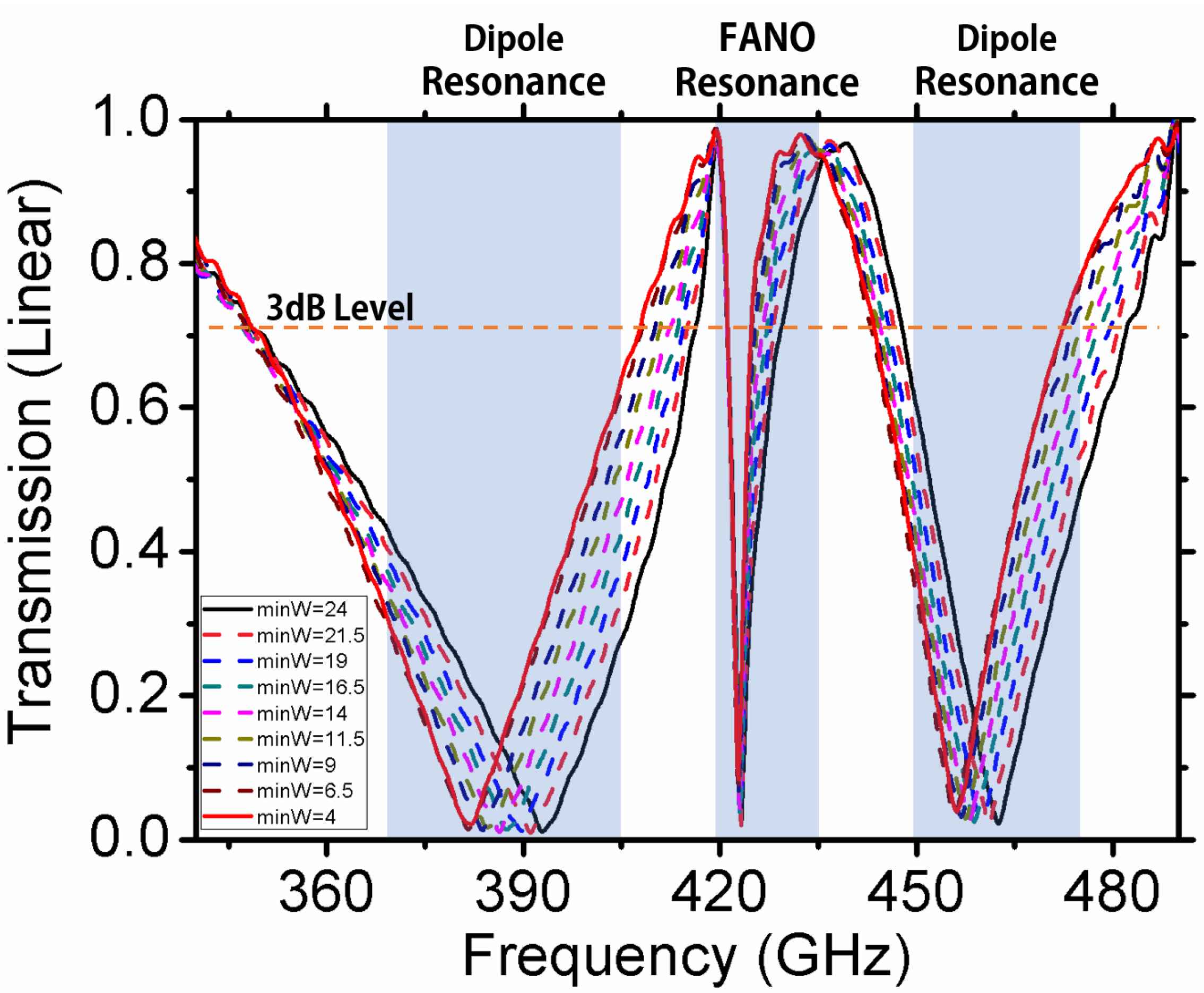
The proposed structure is illustrated in Figure 1a. It looks like two asymmetric crescents placed together oppositely. This shape is created by cutting an ellipse off of a circle that has the same center and cutting a rectangle with a different center. The radius of the circle was 166.5 um, the major axis of the ellipse was 325 um, while the minor axis was 285 um, and the edge of the rectangle going across the center of the circle had a height of 38 um. Asymmetric arcs make the resonant frequency lie nearby, thus the resonances could affect each other through coupling, leading to out-phase-to-in-phase conversion, forming a FANO resonance. FANO resonant frequency of the structure was 420 GHz. A THz wave was projected vertically into the substrate of the structure as shown in Figure 1b, with the E-field polarization perpendicular to the major axis. We tuned the major axis of the ellipse so that the minimum width of the structure could be tuned with a fixed width on the minor-axis direction, so that tip sharpness could be tuned. Simulation results are shown in Figure 2, Figure 3 and Figure 4.
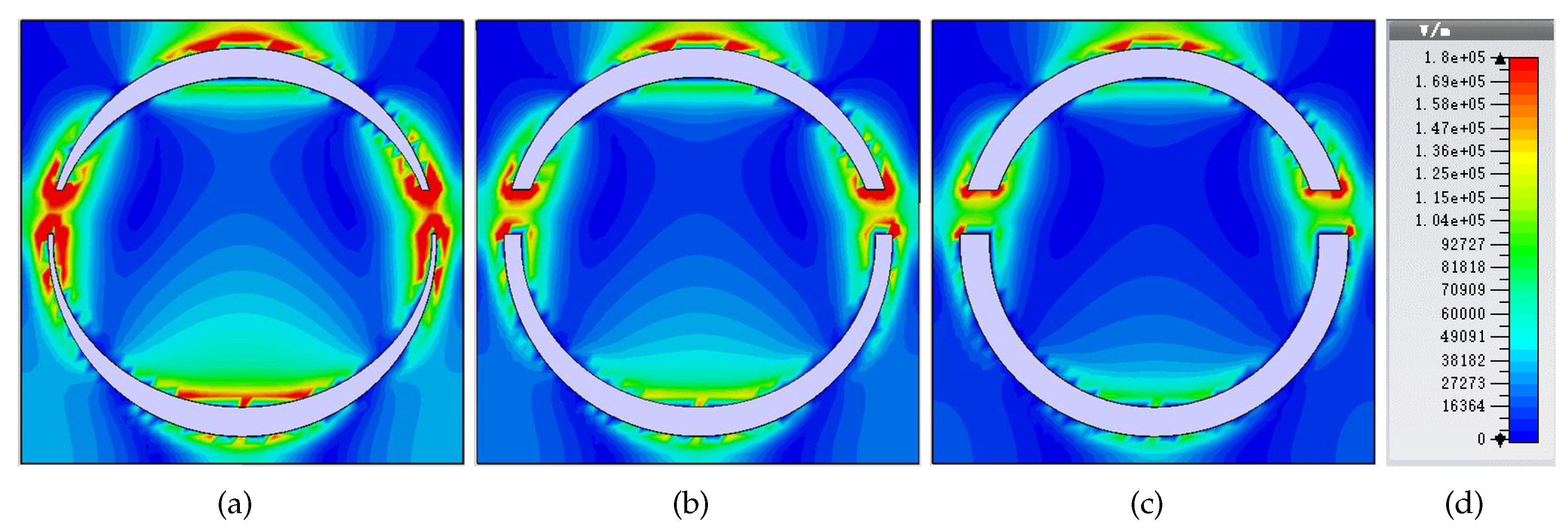
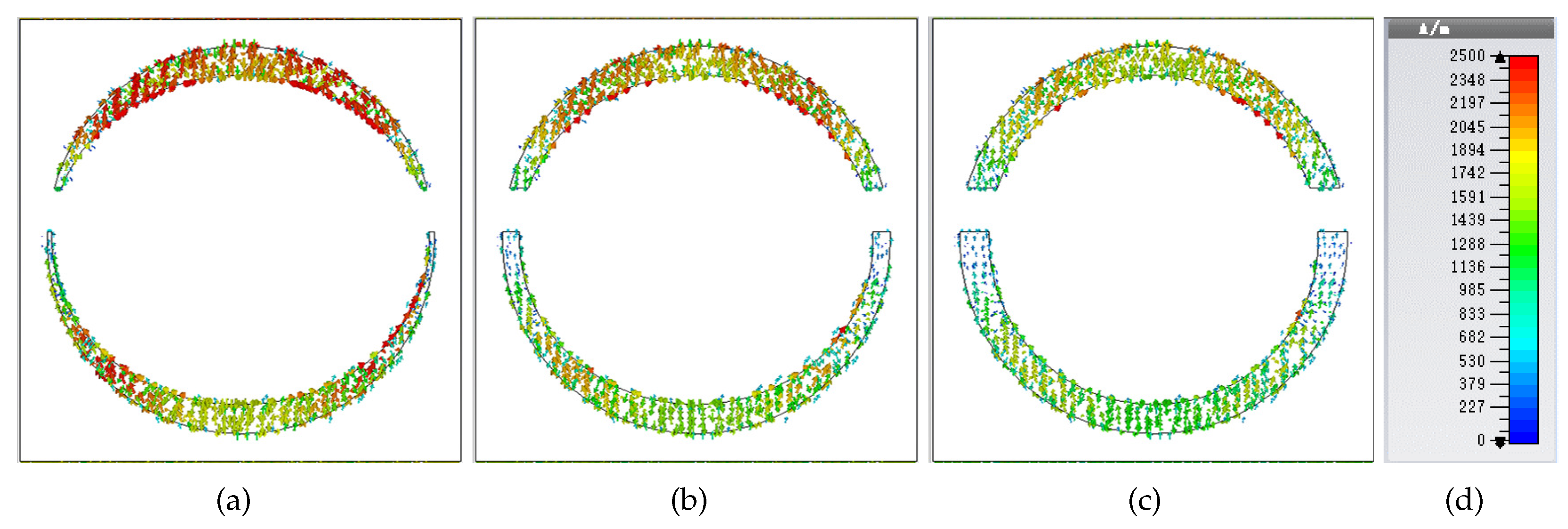
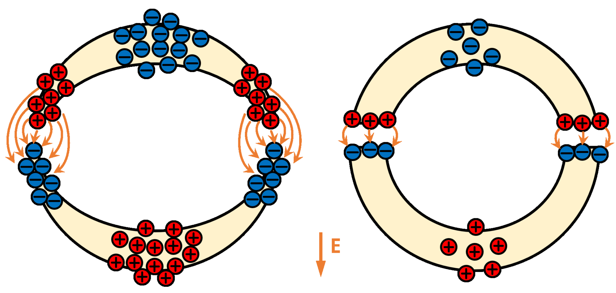
E-field distribution and surface-current distribution are shown in Figure 2 and Figure 3, respectively. It can be observed that the E-field became much stronger when the tips are sharper, and the current is more intense with more charges accumulating at the tips, which leads to greater coupling on tips and enhanced FANO resonance. Figure 5 depicts the working principle of this structure, which could accumulate more charge at the tips because charges always stack at sharp tips. This conclusion could also be drawn from surface–current distribution. With this enhanced FANO resonance, we could obtain a higher-Q factor and maintain resonant intensity within an acceptable range.
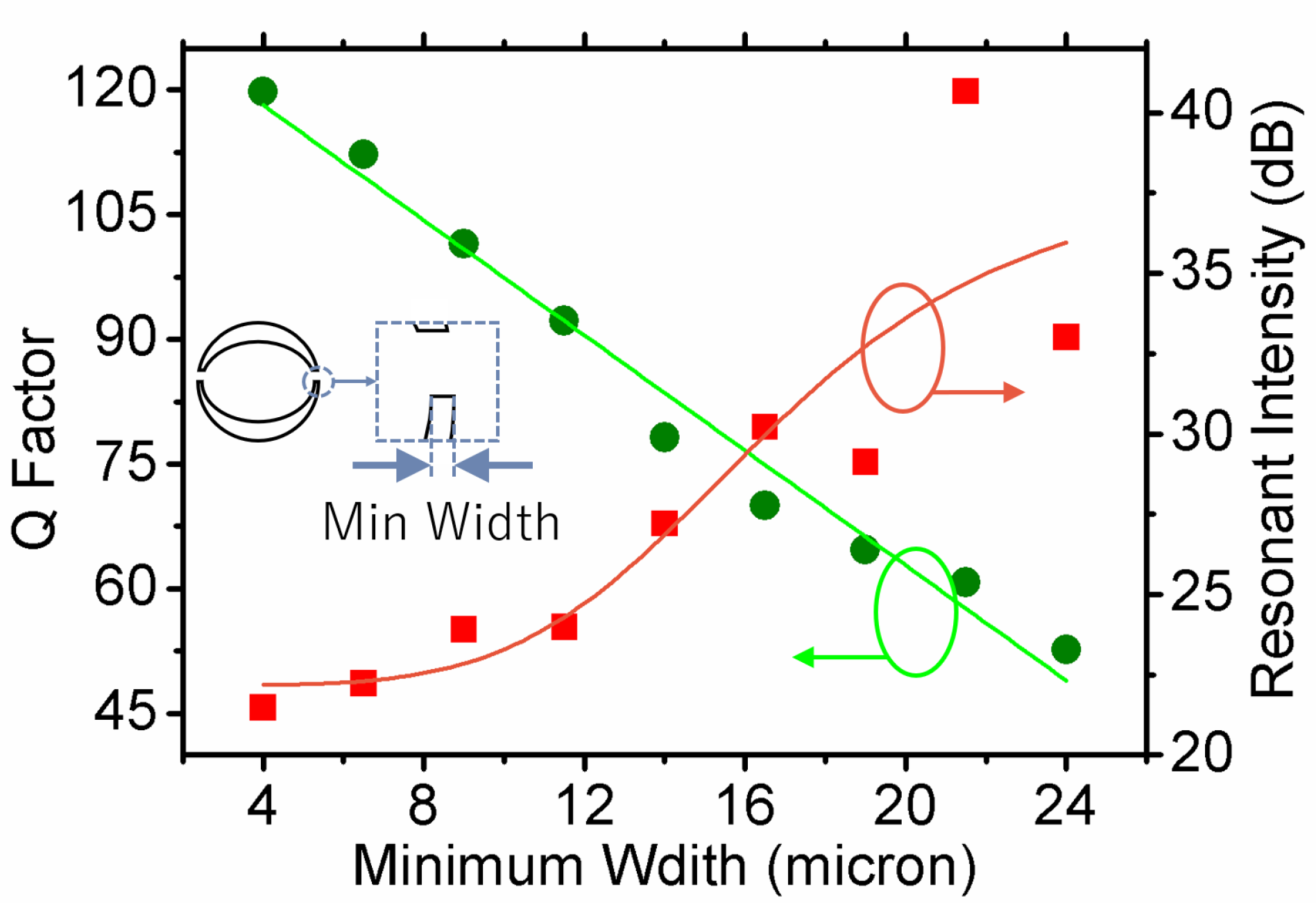
The highest Q could be found with 190 um substrate thickness in the simulation, as shown in Figure 4. The structure we proposed reached a 3 dB Q factor up to 120 compared with 50 of the typical structure, and −20 dB resonance intensity compared with other high-Q structures whose transmission is higher than −10 dB [17]. The relationship between Q factor, resonance intensity and minimum width of the structure was analyzed, as shown in Figure 6. Dots are simulation results and solid lines are the fitted curve. It can be observed from the figure that there was negative correlation between Q factor and minimum width. Resonance intensity and Q factor also showed negative correlation, as described above. In this model, resonance intensity changed in the process of setting the minimum width from 4 to 24 um, and 24 um was the maximum width of the structure. By changing the minimum width under the circumstances of fixed maximum width, sharpness was tuned. However, the transmission was −21.46 dB, still smaller than −20 dB, which still allowed the easy detection of the resonant frequency swinging.

3. Experiments and Discussion

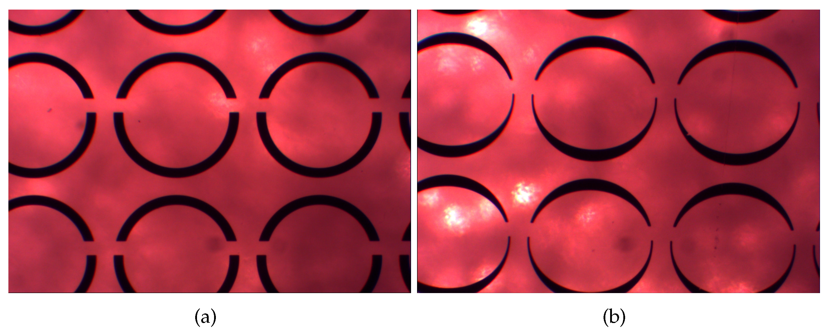
We planned to fabricate a series of FANO structures on the basis of an asymmetric half-ring structure. The substrate was made of quartz with a thickness of 190 um, as shown in Figure 7b. Structure tips were sharpened according to tip-field-enhancement theory, as mentioned above. The width of the widest part was 6.25 times that of the sharpest. A FANO structure without sharpened tips was also fabricated as contrast, as shown in Figure 7a.
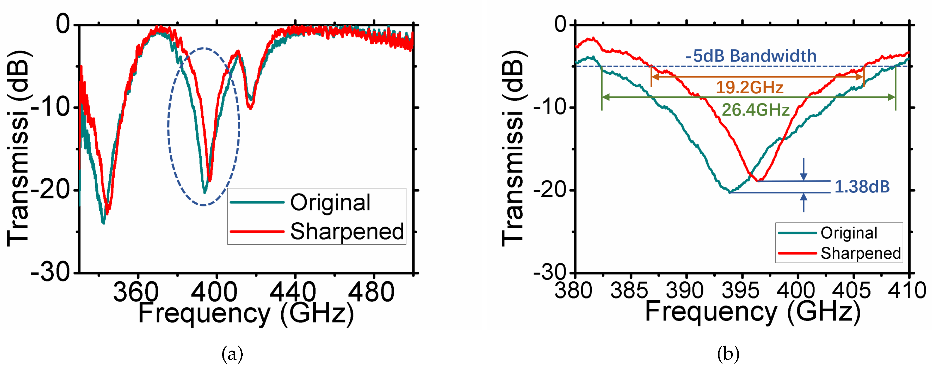
A ZVA 40 with a 330–500 GHz VNA frequency extender, two horn antennas, and a sample holder were used for measurements. The THz wave emitting from the antenna traveled through the sample and was then received by the other antenna. By normalizing the data against a blank quartz sample, the transmission characteristics of the FANO structure could be derived. The THz light spot was confined to the size of the sample, which was 10 × 10 mm. The distance between antenna and sample were set within a range of 50 mm according to the antenna gain. Results are shown in Figure 8.
Due to the dipole resonances at both the high and low side of FANO resonance and loss, −3 dB was not available in the experiment results, as the curve could not reach −3 dB level around FANO resonance. Instead, we used −5 dB bandwidth to characterize its Q factor, which was anticipated to have positive correlation to −3 dB bandwidth. Figure 8 shows that the sharpened structure had a much narrower resonance band than that of a typical structure, while their resonance intensities were at the same level. This result supports the idea that electric charge tend to accumulate at the sharpest points in time-harmonic electromagnetic(EM) fields. Due to the error of thickness and surface-structure shape introduced in the fabrication, the Q factor did not match well with the simulation results. The measured thickness was 177 um. However, it could still be found that the sharper the tips are, the higher the Q that could be obtained. It can be seen from Figure 8 that the Q factor of the sharpened model was 1.37 times larger than that of the originally shaped model, while resonant intensity only declined by 1.38 dB, which is quite small. This experimentally proved that charges do accumulate at sharp tips in time-harmonic electromagnetic(EM) fields.

4. Conclusions

An enhanced FANO resonance structure was proposed in this paper. The methodology is based on the idea that electric charges are more likely to accumulate at the sharpest tips in a static E-field. Both simulation and experiment results showed that the Q factor of the proposed structure could be increased to up to 2.4 times compared to the original, without sacrificing too much resonance intensity. E-field and surface-current distribution also showed that the charges indeed do accumulate at tips, which enhanced the coupling between the tips. This result also proves that the law of tip-field-enhancement theory could also be applied to time-harmonic electromagnetic (EM) fields. With this method, sensitivity and accuracy could be improved in existing FANO-based micro-fluidic sensors. Tip-field-enhancement theory could also be beneficial to other fields of research, such as antenna design, where the control of charge and current distribution is required.

Author Contributions

Conceptualization, T.Z., B.Z. and Y.Z.; methodology, T.Z., B.Z., Y.Z. and K.S.; investigation, T.Z., B.Z. and L.W.; resources, S.L.; supervision, Y.Z.; validation, T.Z. and B.Z.; Writing—review and editing, C.S.

Funding

This work is supported by the The National Key Research and Development Program of China under Contract No. 2018YFB1801503, National Natural Science Foundation of China under Contract Nos. 61931006, 61921002 and 61771327.

Conflicts of Interest

The authors declare no conflict of interest.

References

  1. Chang, C.C.; Huang, L.; Nogan, J.; Chen, H.T. Narrowband terahertz bandpass filters employing stacked bilayer metasurface antireflection structures. APL Photonics 2018, 3, 051602. [Google Scholar] [CrossRef]
  2. Zhang, Y.; Zhao, Y.; Liang, S.; Zhang, B.; Wang, L.; Zhou, T.; Kou, W.; Lan, F.; Zeng, H.; Han, J.; et al. Large phase modulation of THz wave via an enhanced resonant active HEMT metasurface. Nanophotonics 2019, 8, 153–170. [Google Scholar] [CrossRef]
  3. Zhao, Y.; Zhang, Y.; Shi, Q.; Liang, S.; Huang, W.; Kou, W.; Yang, Z. Dynamic Photoinduced Controlling of the Large Phase Shift of Terahertz Waves via Vanadium Dioxide Coupling Nanostructures. ACS Photonics 2018, 5, 3040–3050. [Google Scholar] [CrossRef]
  4. Zhao, W.; Jiang, H.; Liu, B.; Jiang, Y.; Tang, C.; Li, J. Fano resonance based optical modulator reaching 85% modulation depth. Appl. Phys. Lett. 2015, 107, 171109. [Google Scholar] [CrossRef]
  5. Shen, N.; Tassin, P.; Koschny, T.; Soukoulis, C.M. Comparison of gold- and graphene-based resonant nanostructures for terahertz metamaterials and an ultrathin graphene-based modulator. Phys. Rev. B 2014, 90, 115437. [Google Scholar] [CrossRef]
  6. Keiser, G.R.; Karl, N.; Liu, P.Q.; Tulloss, C.; Chen, H.-T.; Taylor, A.J.; Brener, I.; Reno, J.L.; Mittleman, D.M. Nonlinear terahertz metamaterials with active electrical control. Appl. Phys. Lett. 2017, 111, 121101. [Google Scholar] [CrossRef]
  7. Awang, R.A.; Tovar-Lopez, F.J.; Baum, T.; Sriram, S.; Rowe, W.S.T. Meta-atom microfluidic sensor for measurement of dielectric properties of liquids. Phys. Rev. Appl. 2017, 121, 094506. [Google Scholar] [CrossRef]
  8. Roh, Y.; Lee, S.; Kang, B.; Wu, J.W.; Ju, B.; Seo, M. Terahertz optical characteristics of two types of metamaterials for molecule sensing. Optics Express 2019, 27, 19042. [Google Scholar] [CrossRef]
  9. Xu, H.; Zhao, M.; Chen, Z.; Zheng, M.; Xiong, C.; Zhang, B.; Li, H. Sensing analysis based on tunable Fano resonance in terahertz graphene-layered metamaterials. J. Appl. Phys. 2018, 123, 203103. [Google Scholar] [CrossRef]
  10. Srivastava, Y.K.; Cong, L.; Singh, R. Dual-surface flexible THz Fano metasensor. Appl. Phys. Lett. 2017, 111, 201101. [Google Scholar] [CrossRef]
  11. Miyazaki, H.T.; Kasaya, T.; Iwanaga, M.; Choi, B.; Sugimoto, Y.; Sakoda, K. Dual-band infrared metasurface thermal emitter for CO2 sensing. Appl. Phys. Lett. 2014, 105, 121107. [Google Scholar] [CrossRef]
  12. Wang, H.; Li, Y.; Han, Y.; Fan, Y.; Sui, S.; Chen, H.; Wang, J.; Cheng, Q.; Cui, T.; Qu, S. Vortex beam generated by circular-polarized metasurface reflector antenna. J. Phys. D Appl. Phys. 2019, 121, 094506. [Google Scholar] [CrossRef]
  13. Wang, J.; Wang, S.; Singh, R.; Zhang, W. Metamaterial inspired terahertz devices: From ultra-sensitive sensing to near field manipulation. COL 2013, 11, 011602. [Google Scholar]
  14. Fedotov, V.A.; Rose, M.; Prosvirnin, S.L.; Papasimakis, N.; Zheludev, N.I. Sharp Trapped-Mode Resonances in Planar Metamaterials with a Broken structural Symmetry. Phys. Rev. Lett. 2007, 99, 147401. [Google Scholar] [CrossRef] [PubMed]
  15. Gu, Z.; Zhao, Z.; Zhao, H.; Peng, W.; Zhang, J.; Shi, W. Fano-resonance collapse induced terahertz magnetic dipole oscillation in complementary meta-atoms via local symmetry breaking. J. Appl. Phys. 2019, 125, 143102. [Google Scholar] [CrossRef]
  16. Singh, R.; Cao, W.; Al-Naib, I.; Cong, L.; Withayachumnankul, W.; Zhang, W. Ultrasensitive terahertz sensing with high-Q Fano resonances in metasurfaces. Appl. Phys. Lett. 2014, 105, 171101. [Google Scholar] [CrossRef]
  17. Singh, R.; Al-Naib, I.A.I.; Koch, M.; Zhang, W. Sharp Fano resonances in THz metamaterials. Optics Express 2011, 19, 6312–6319. [Google Scholar] [CrossRef]
  18. Shen, Z.X.; Zhou, S.H.; Ge, S.J.; Hu, W.; Lu, Y.Q. Liquid crystal enabled dynamic cloaking of terahertz Fano resonators. Appl. Phys. Lett. 2019, 114, 041106. [Google Scholar] [CrossRef]
  19. Aydin, K.; Pryce, I.M.; Atwater, H.A. Symmetry breaking and strong coupling in planar optical metamaterials. Optics Express 2010, 18, 13407. [Google Scholar] [CrossRef]
  20. Miyamaru, F.; Kubota, S.; Nakanishi, T.; Kawashima, S.; Sato, N.; Kitano, M.; Takeda, M.W. Transmission properties of double-gap asymmetric split ring resonators in terahertz region. Appl. Phys. Lett. 2012, 101, 051112. [Google Scholar] [CrossRef]
  21. Khanikaev, A.B.; Mousavi, S.H.; Wu, C.; Dabidian, N.; Alici, K.B.; Shvets, G. Fano-resonant Electrically Connected Meta-surfaces with High Quality Factors. In Proceedings of the Quantum Electronics and Laser Science Conference, San Jose, CA, USA, 6–11 May 2012. [Google Scholar] [CrossRef]
  22. Fan, Y.; Wei, Z.; Li, H.; Chen, H.; Soukoulis, C.M. Low-loss and high-Q planar metamaterial with toroidal moment. Phys. Rev. B 2013, 87, 115417. [Google Scholar] [CrossRef]
  23. Srivastava, Y.K.; Singh, R. Impact of conductivity on Lorentzian and Fano resonant high-Q THz metamaterials: Superconductor, metal and perfect electric conductor. J. Appl. Phys. 2017, 122, 183104. [Google Scholar] [CrossRef]
  24. Rybin, M.V.; Koshelev, K.L.; Sadrieva, Z.F.; Samusev, K.B.; Bogdanov, A.A.; Limonov, M.F.; Kivshar, Y.S. High-Q Supercavity Modes in Subwavelength Dielectric Resonators. Phys. Rev. Lett. 2017, 199, 243901. [Google Scholar] [CrossRef]
  25. Zhang, F.; Huang, X.; Zhao, Q.; Chen, L.; Wang, Y.; Li, Q.; He, X.; Li, C.; Chen, K. Fano resonance of an asymmetric dielectric wire pair. Appl. Phys. Lett. 2014, 105, 172901. [Google Scholar] [CrossRef]
  26. Parry, M.; Komar, A.; Hopkins, B.; Campione, S.; Liu, S.; Miroshnichenko, A.E.; Nogan, J.; Sinclair, M.B.; Brener, I.; Neshev, D.N. Active tuning of high-Q dielectric metasurfaces. Appl. Phys. Lett. 2017, 111, 053102. [Google Scholar] [CrossRef]
  27. Karmakar, S.; Varshney, R.K.; Chowdhury, D.R. Theoretical investigation of active modulation and enhancement of Fano resonance in THz metamaterials. OSA Continuum 2019, 2, 531–539. [Google Scholar] [CrossRef]
  28. Koshelev, K.; Lepeshov, S.; Liu, M.; Bogdanov, A.; Kivshar, Y. Asymmetric Metasurfaces with High-Q Resonances Governed by Bound States in the Continuum, metal and perfect electric conductor. Phys. Rev. Lett. 2018, 121, 193903. [Google Scholar] [CrossRef]
  29. Rana, G.; Deshmukh, P.; Palkhivala, S.; Gupta, A.; Duttagupta, S.P.; Prabhu, S.S.; Achanta, V.; Agarwal, G.S. Quadrupole-Quadrupole Interactions to Control Plasmon-Induced Transparency. Phys. Rev. Appl. 2018, 9, 064015. [Google Scholar] [CrossRef]
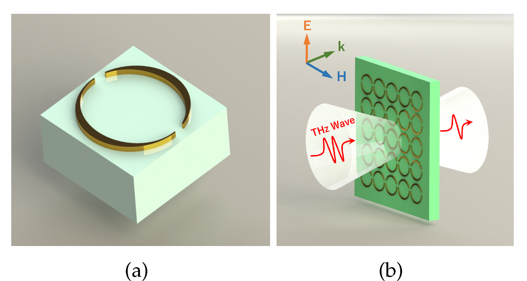
Figure 1. (a) Unit cell of enhanced FANO structure. (b) THz wave cast perpendicularly onto structure with vertical E polarization.
Applsci 09 05009 g001
Figure 2. (ac) Simulated E-field distribution of three structures with different tip sharpness. (d) is the color bar of the previous figures.
Applsci 09 05009 g002
Figure 3. (ac) Simulated surface-current distribution of three structures with different tip sharpness. (d) is the color bar of the previous figures.
Applsci 09 05009 g003
Figure 4. Simulation result while tuning structure’s minimum width. minW: minimum width. Maximum width of the structure was fixed, so minimum width indicates tip sharpness. Solid lines: transmission characteristics of structure with sharpest tips and unsharpened structure. With minimum-width increase, 3 dB bandwidth increased, thus its 3 dB Q factor decreased.
Applsci 09 05009 g004
Figure 5. Model schematic. Charge is more likely to accumulate at sharp tips, leading to intense coupling between tips, enhancing FANO resonance.
Applsci 09 05009 g005
Figure 6. Minimum width of structure has negative correlation with Q factor, while Q factor has negative correlation with resonant intensity. Q factor varies linearly with minimum width, and there seems to be a limit of highest possible Q factor, slightly larger than 120. Non-monotonicity of resonance intensity was probably because resonant intensity was so small that there could be a computational error.
Applsci 09 05009 g006
Figure 7. (a) Original and (b) enhanced FANO structure under microscope.
Applsci 09 05009 g007
Figure 8. Experiment results. (a) All three resonances: two dipole resonances and a FANO resonance. (b) Enlarged curve at FANO resonant frequency (circled in (a)). Curve descends rapidly out of the large figure zone due to the existence of two dipole resonances at both the high end and the low end, so it could not reach −3 dB near one end of FANO resonate frequency. We used −5 dB bandwidth.
Applsci 09 05009 g008