Article

A Flutter-Based Electromagnetic Wind Energy Harvester: Theory and Experiments

1
Microsystem Research Center, College of Optoelectronic Engineering, Chongqing University, Chongqing 400044, China
2
Key Laboratory of Fundamental Science of Micro/Nano-Device and System Technology, Chongqing University, Chongqing 400044, China
3
Fraunhofer ENAS, Technologie-Campus 3, 09126 Chemnitz, Germany
*
Authors to whom correspondence should be addressed.
Appl. Sci. 2019, 9(22), 4823; https://doi.org/10.3390/app9224823
Submission received: 11 October 2019 / Revised: 31 October 2019 / Accepted: 7 November 2019 / Published: 11 November 2019
(This article belongs to the Special Issue Wind Power Systems: Design, Operation, and Control)

Abstract

:
Wind energy harvesting is a promising way to offer power supply to low-power electronic devices. Miniature wind-induced vibration energy harvesters, which are currently being focused on by researchers in the field, offer the advantages of small volume and simple structure. In this article, an analytical model was proposed for the kinetic analysis of a flutter-based electromagnetic wind energy harvester. As a result, the critical wind speeds of energy harvesters with different magnet positions were predicted. To experimentally verify the analytical predictions and investigate the output performance of the proposed energy harvester, a small wind tunnel was built. The critical wind speeds measured by the experiment were found to be consistent with the predictions. Therefore, the proposed model can be used to predict the critical wind speed of a wind belt type energy harvester. The experimental results also show that placing the magnets near the middle of the membrane can result in lower critical wind speed and higher output performance. The optimized wind energy harvester was found to generate maximum average power of 705 μW at a wind speed of 10 m/s, offering application prospects for the power supply of low-power electronic devices. This work can serve as a reference for the structural design and theoretical analysis of a flutter-based wind energy harvester.

1. Introduction

Low-power electronic devices, such as wireless sensor networks [1], portable electronics [2], and implanted systems [3], have made great progress in recent years. Traditionally, batteries were employed as a primary power source for such devices; however, their limited life challenges the long-term operation of devices, and their disposal poses environmental concerns [4,5]. Harvesting ambient energy—Solar, vibration, and wind energy—and converting them to electric power is a prospective solution [6,7,8,9]. Among all of the energy sources, wind energy has attracted much attention over the past decades due to its clean, renewable, and widespread existence. The conventional wind turbine has disadvantages of large volume, complicated structure, and high cost to power low-power electronic devices [5,10]; researchers are, thus, keen to find simpler ways to harvest wind energy.
An energy harvester based on wind-induced vibration (WIV) offers simple mechanisms to harvest wind energy, such as vortex-induced vibration (VIV), flutter, etc. VIV [11,12] is a phenomenon wherein airflow interacts with the buff body, while the vortex sheds from the buff body; there is a period of aerodynamic force being applied to the body and the structure behind it. If the vortex shedding frequency is close to the natural frequency of the elastic structure, a resonance phenomenon takes place and the amplitude increases dramatically. Dai et al. [13] compared the output performance of a piezoelectric energy harvester with different orientations of buff body; the results confirm that the vortex-induced aerodynamic force acts on both the buff body and the rear cantilever. Differing from VIV, flutter is a self-excited vibration phenomenon—The aerodynamic forces mainly come from the vibration of the structure itself, which is possible when the total damping is negative. According to the number of vibrational degrees of freedom, flutter can be divided into two forms: single-freedom flutter (also known as galloping) [14,15,16] and bend-torsion coupled flutter [17,18]. Galloping is normally observed in lightweight prismatic structures (square, triangle, D-section, and so on). VIV and galloping may occur simultaneously. He et al. [19] investigated the performance of a piezoelectric energy harvester by utilizing buff bodies with a different rectangular section; the results show the enhancement of wind energy harvesting on interaction between VIV and galloping. Bend-torsion coupled flutter usually occurs in plate-like structures, such as membranes, flat plates, and airfoils. Li et al. [20] proposed the concept of bionic tree, wherein hundreds of leaf-like piezoelectric energy harvesters show prospects for high-power applications.
When compared to piezoelectric energy harvesters, electromagnetic energy harvesters offer the advantage of lower internal resistance, which results in a higher current. Frayne [21,22,23] invented a flutter-based electromagnetic wind energy harvester, known as the wind belt. The energy harvester had an extremely simple structure consisting of three parts: a doubly-clamped membrane, two pieces of magnets, and one or more coils. Frayne claimed that the energy harvester—With two dimensions of 12 cm and 1 m—Could be used for the power supply of an island. Fei et al. [24] introduced the aerodynamic forces of the wind belt and designed a power management circuit for the energy harvester. Quy et al. [25] experimentally investigated the effects of axial tension, angle of attack, and position of magnets on critical wind speed, oscillating frequency, and output performance of the energy harvester. Aquino et al. [26,27] made a wind belt with a length of 0.5 m and simulated the wind field around buildings; they also suggested the optimal installation location of the energy harvester. However, although a series of experiments have been conducted on the wind belt type energy harvester, an analytical model to systematically analyze its behavior is missing.
In this paper, an analytical model for the wind belt type energy harvester is proposed. Modal analysis of the model agrees well with that of the finite element simulation. The results of flutter analysis indicate that flutter at low airflow speed mainly comes from the coupling of the first bending and torsional modes. The calculated critical wind speed was consistent with previous empirical formulae and the experimental results. The influence of the magnets’ positions was also investigated. The results suggest that by placing the magnets near the middle of the membrane, the performance of the system could be further improved. The optimized wind energy harvester can generate a maximum average power of 705 μW at wind speed of 10 m/s., showcasing a promising future as a power supplier for low-power consumption devices. This work shows significance of the structure design and performance improvement of the flutter-based wind energy harvester.

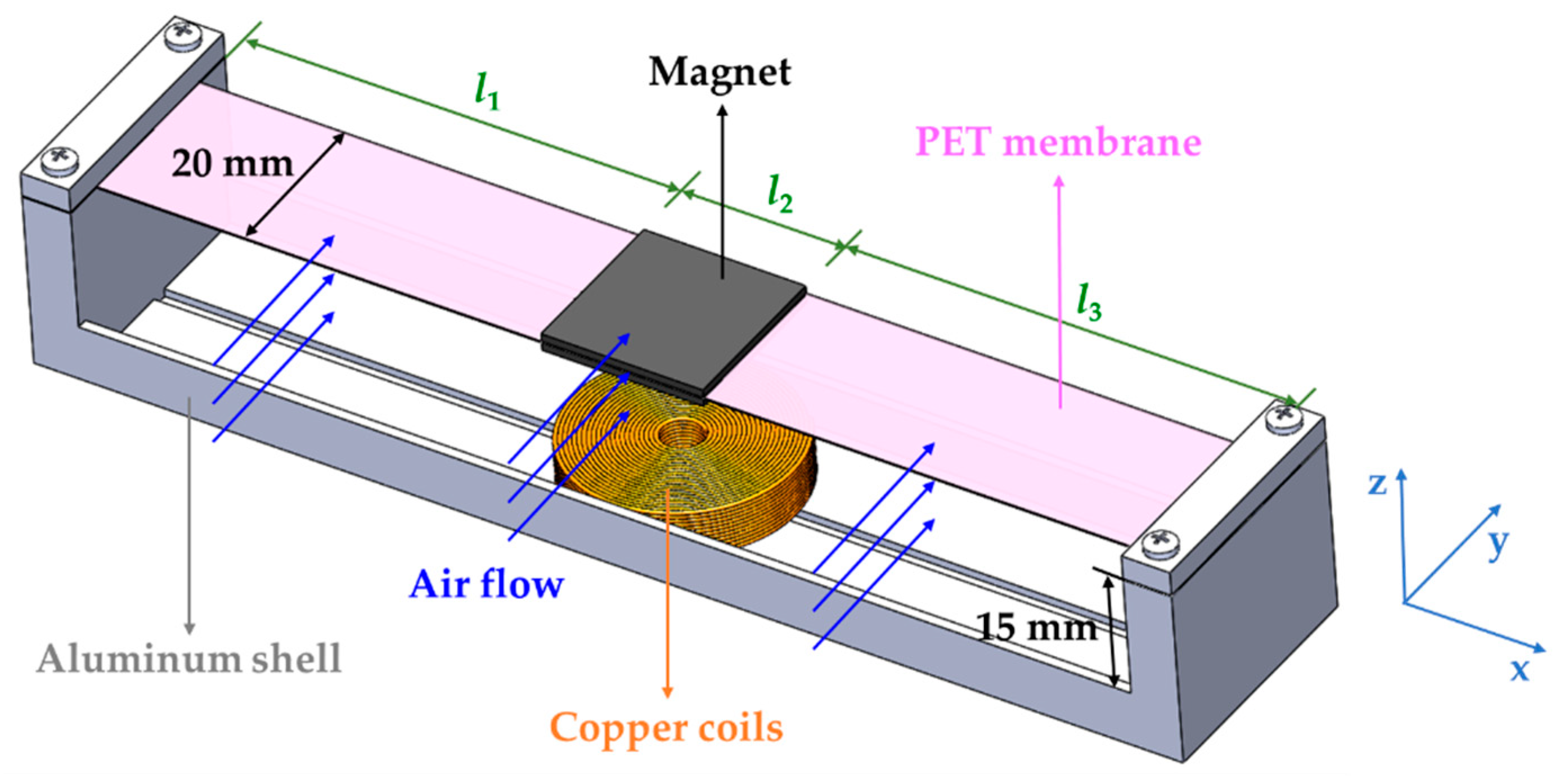
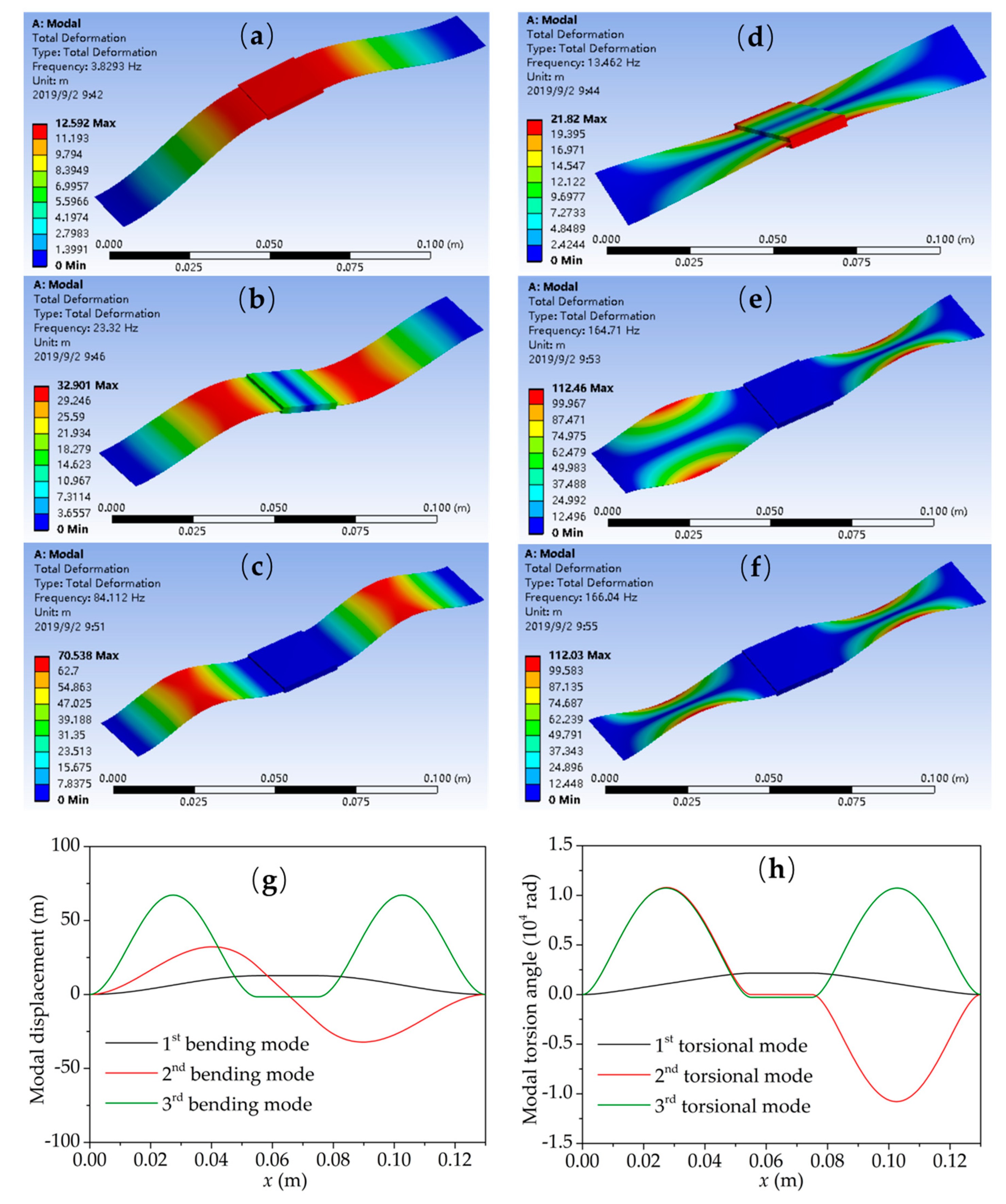
2. Device Structure and Modal Analysis
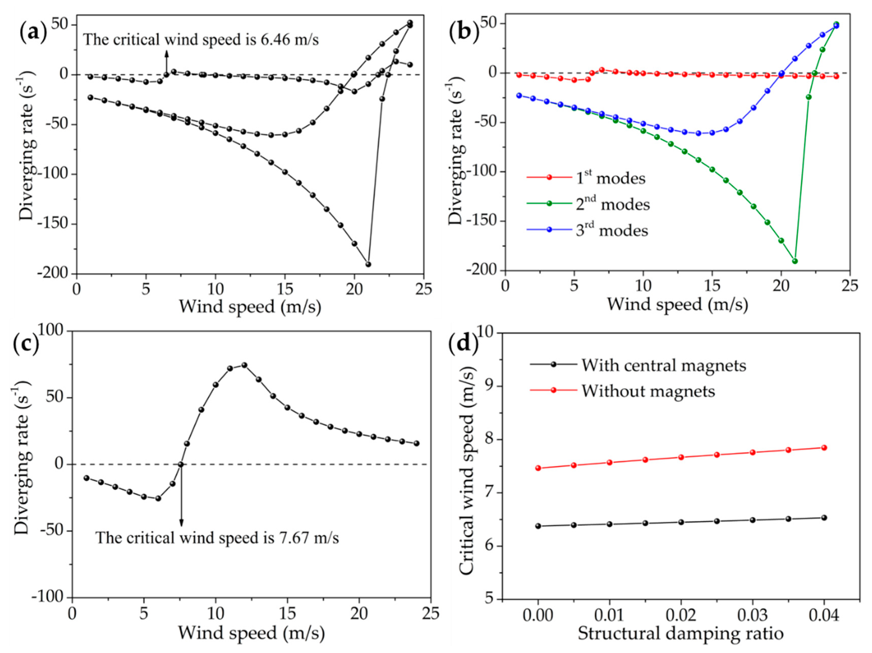
The structure of the proposed wind energy harvester is illustrated in Figure 1; it mainly consists of four parts: a flexible polyethylene terephthalate (PET) membrane, two pieces of magnets, a set of copper coils, and an aluminum shell. The material and structural parameters of the wind energy harvester are given in Table 1. The PET membrane was doubly clamped by four screws. The N35 NdFeB magnets were attached to the PET membrane, which were magnetized along the thickness direction. The coils were as close to the magnets as possible for higher voltage and electric power. The overall dimensions of the device are 142 mm × 30 mm × 25 mm. The wind direction is perpendicular to the axis of the PET membrane. When wind speed is higher than the flutter critical wind speed, the PET membrane combined with magnets oscillate with a large amplitude, and the energy harvester generates high electric power based on Faraday’s law of electromagnetic induction.
The vibrational structure of the energy harvester only consists of a doubly-clamped PET membrane and two pieces of magnet, which is similar to a bridge. It vibrates with two degrees of freedom in the wind: bending and torsion. Modal analysis is the foundation of flutter analysis; the bending modal can be obtained from the Euler beam equation with undamped free vibration [17,30]
( E I ) i 4 h i ( x i , t ) x i 4 + μ i 2 h i ( x i , t ) t 2 = 0 , i = 1 , 2 , 3
where (EI)i, μi, xi and hi represent bending stiffness, the linear density, the coordinate, and the bending displacement of the ith section, respectively; t is the time. The method of separation of variables can be used to solve Equation (1) by separating the spatial and temporal functions as h i ( x i , t ) = ϕ i ( x i ) p ( t ) [31]. Thus, we can obtain:
p ( t ) = A sin ω h t + B cos ω h t
ϕ i ( x i ) = A i sinh ( λ i x i ) + B i cosh ( λ i x i ) + C i sin ( λ i x i ) + D i cos ( λ i x i )
where ϕi and p represent variables related to coordinate and time, respectively, ωh is the bending angular frequency, λ i = [ ω h 2 μ i / ( E I ) i ] 1 / 4 A, B, Ai, Bi, Ci and Di are undetermined coefficients. The boundary conditions are:
ϕ 1 ( 0 ) = 0 ,   ϕ 1 ( x 1 ) x 1 | x 1 = 0 = 0 ,   ϕ 3 ( l 3 ) = 0 ,   ϕ 3 ( x 3 ) x 3 | x 3 = l 3 = 0 ϕ i ( l i ) = ϕ i + 1 ( 0 ) ,   ϕ i ( x i ) x i | x i = l i = ϕ i + 1 ( x i + 1 ) x i + 1 | x i + 1 = 0 ( E I ) i 2 ϕ i ( x i ) x i 2 | x i = l i = ( E I ) i + 1 2 ϕ i + 1 ( x i + 1 ) x i + 1 2 | x i + 1 = 0 ( E I ) i 3 ϕ i ( x i ) x i 3 | x i = l i = ( E I ) i + 1 3 ϕ i + 1 ( x i + 1 ) x i + 1 3 | x i + 1 = 0
li is the length of each section. By substituting Equation (3) into the boundary conditions (4), and considering the orthogonal normalization condition (to obtain the bending vibration modes):
i μ i 0 l i ϕ i r ( x i ) ϕ i s ( x i ) d x i = δ r s
where r and s represent the rth and sth bending mode, respectively, δrs is the Kronecker delta (δrs=0 when rs and δrs = 1 when r = s). We can obtain:
λ i = λ i r ,   f h r = ω h r 2 π = λ i r 2 2 π ( E I ) i μ i ,   ϕ i ( x i ) = ϕ i r ( x i ) ,   p ( t ) = p r ( t ) ,   r = 1 , 2 ,
where fhr, ϕr, pr represents the rth bending natural frequency, the rth bending vibration mode, and the rth bending modal, respectively. Bending displacement hi can be written as:
h i ( x i , t ) = r ϕ i r ( x i ) p r ( t )
Similar to the bending modal, the torsional modal can be obtained from the following equation:
( E I ω ) i 4 α i ( x i , t ) x i 4 ( G I t ) i 2 α i ( x i , t ) x i 2 + ( ρ I m ) i 2 α i ( x i , t ) t 2 = 0 , i = 1 , 2 , 3
where (EIω)i, (GIt)i, (ρIm)i and αi represent the warping stiffness, the torsional stiffness, the moment of inertial per unit length, and the twist angle of the ith section, respectively. Equation (8) can also be solved by separating variables as α i ( x i , t ) = φ i ( x i ) q ( t ) [31], where:
q ( t ) = S sin ω α t + T cos ω α t
φ i ( x i ) = S i sinh ( m i x i ) + T i cosh ( m i x i ) + U i sin ( n i x i ) + V i cos ( n i x i )
m i = 4 χ i 2 + k i 2 + k i 2 ,   n i = 4 χ i 2 + k i 2 k i 2 ,   k i = ( G I t ) i ( E I ω ) i
where φi and q represent variables related to coordinate and time, respectively; ωα is the torsional angular frequency, χ i = ω α 2 ( E I ω ) i / ( ρ I m ) i , S, T, Si, Ti, Ui, and Vi are undetermined coefficients. The boundary conditions are:
φ 1 ( 0 ) = 0 ,   φ 1 ( x 1 ) x 1 | x 1 = 0 = 0 ,   φ 3 ( l 3 ) = 0 ,   φ 3 ( x 3 ) x 3 | x 3 = l 3 = 0 φ i ( l i ) = φ i + 1 ( 0 ) ,   φ i ( x i ) x i | x i = l i = φ i + 1 ( x i + 1 ) x i + 1 | x i + 1 = 0 ( G I t ) i φ i ( x i ) x i | x i = l i = ( G I t ) i + 1 φ i + 1 ( x i + 1 ) x i + 1 | x i + 1 = 0 ( E I ω ) i 3 φ i ( x i ) x i 3 | x i = l i = ( E I ω ) i + 1 3 φ i + 1 ( x i + 1 ) x i + 1 3 | x i + 1 = 0
By substituting Equation (10) into the boundary conditions (12), and considering the orthogonal normalization condition (to obtain the torsional vibration modes):
i ( ρ I m ) i 0 l i φ i u ( x i ) φ i v ( x i ) d x i = δ u v
where u and v represent the uth and vth torsional mode, respectively; δuv is the Kronecker delta (δuv = 0 when uv and δuv = 1 when u = v). We can obtain:
χ i = χ i u ,   f α u = ω α u 2 π = χ i u 2 π ( ρ I m ) i ( E I ω ) i ,   φ i ( x i ) = φ i u ( x i ) ,   q ( t ) = q u ( t ) ,   u = 1 , 2 ,
where fαu, φu, qu represents the uth torsional natural frequency, the uth torsional vibration mode and the uth torsional modal, respectively. The torsion angle αi can be written as:
α i ( x i , t ) = u φ i u ( x i ) q u ( t )
The modal of the structure can be obtained by finite element simulation as well, which has been used for verification of modal analysis by the analytical model. Figure 2 and Table 2 show the first three bending and torsional vibration modes and the corresponding natural frequencies by finite element simulation (ANSYS workbench) and the derived analytical model, respectively (the magnets are located in the middle of the PET membrane). We can see that the results of the derived analytical model and the finite element simulation are consistent, which demonstrates that the derived analytical model is reliable. The errors of natural frequencies between the analytical model and the finite element results are less than 5%. The errors mainly come from the constraint of the derived analytical model on the freedom of vibration. In addition, the first and third bending and torsional vibration modes are symmetric to the perpendicular bisector of magnets, and the second bending and torsional vibration modes are anti-symmetric around the midpoint of the magnets. Therefore, it is easy to produce coupled flutter due to similarity between the bending and torsional vibration modes of the same order. There is no coupling between the adjacent bending and torsional modes (refer to the definition of Λru in Equation (34)).

3. Flutter Analysis

The dynamical equations of the energy harvester in wind can be written as:
μ i 2 h i ( x i , t ) t 2 + c h i h i ( x i , t ) t + ( E I ) i 4 h i ( x i , t ) x i 4 = L i
( ρ I m ) i 2 α i ( x i , t ) t 2 + c α i α i ( x i , t ) t + ( E I ω ) i 4 α i ( x i , t ) x i 4 ( G I t ) i 2 α i ( x i , t ) x i 2 = M i
where chi and cαi represent the structural damping of bending and torsion of each section, respectively; Li and Mi are the aerodynamic lift force and torque per unit length, respectively [24].
L i = π ρ a b { b h ¨ i 2 U C ( k ) h ˙ i [ 1 + C ( k ) ] U b α ˙ i 2 U 2 C ( k ) α i }
M i = π ρ a b 2 { U C ( k ) h ˙ i b 2 8 α ¨ i + [ 1 2 + 1 2 C ( k ) ] U b α ˙ i + U 2 C ( k ) α i }
where ρa = 1.226 kg/m3 is the density of air (15 °C), b is the half width of the PET membrane, U is the wind speed, k = ωb/U is the non-dimensional frequency, ω is the flutter angular frequency, and C(k) is Theodorsen’s circulation function [32,33]
C ( k ) = F ( k ) + i G ( k )
where [33]
F ( k ) = 1 0.165 1 + ( 0.0455 k ) 2 0.335 1 + ( 0.3 k ) 2 ,   G ( k ) = 0.165 × 0 . 0455 k 1 + ( 0.0455 k ) 2 0.335 × 0.3 k 1 + ( 0.3 k ) 2
For the dynamic equations to be valid throughout the time domain, the diverging rate and frequency of both bending and torsion should be same; thus, we can assume:
p r ( t ) = P r e ( δ + i ω ) t
q u ( t ) = Q u e ( δ + i ω ) t
where δ is the diverging rate, ω is the angular frequency. By substituting Equations (7) and (15) into the dynamical equations, and considering the orthogonal normalization conditions (Equations (5) and (13)), we can obtain:
( a r + b r i ) p r ( t ) + u ( m + n i ) Λ r u q u ( t ) = 0
r ( p + q i ) Λ r u p r ( t ) + ( c u + d u i ) q u ( t ) = 0
where
a r = ( δ 2 ω 2 ) ( 1 + π ρ a b 2 A r ) + 2 ζ h r ω h r δ + 2 π ρ a b U F ( k ) δ A r 2 π ρ a b U G ( k ) ω A r + ω h r 2
b r = 2 δ ω ( 1 + π ρ a b 2 A r ) + 2 ζ h r ω h r ω + 2 π ρ a b U F ( k ) ω A r + 2 π ρ a b U G ( k ) δ A r
m = π ρ a b 2 U δ + π ρ a b 2 U F ( k ) δ + 2 π ρ a b U 2 F ( k ) π ρ a b 2 U G ( k ) ω
n = π ρ a b 2 U ω + π ρ a b 2 U F ( k ) ω + π ρ a b 2 U G ( k ) δ + 2 π ρ a b U 2 G ( k )
p = π ρ a b 2 U F ( k ) δ + π ρ a b 2 U G ( k ) ω
q = π ρ a b 2 U G ( k ) δ π ρ a b 2 U F ( k ) ω
  c u = ( δ 2 ω 2 ) ( 1 + π ρ a b 4 8 B u ) + 2 ζ α u ω α u δ + π ρ a b 3 U δ 2 B u π ρ a b 3 U F ( k ) δ 2 B u + π ρ a b 3 U G ( k ) ω 2 B u + ω α u 2 π ρ a b 2 U 2 F ( k ) B u
d u = 2 ω δ ( 1 + π ρ a b 4 8 B u ) π ρ a b 3 U G ( k ) δ 2 B u + 2 ζ α u ω α u ω + π ρ a b 3 U ω 2 B u π ρ a b 3 U F ( k ) ω 2 B u π ρ a b 2 U 2 G ( k ) B u
A r = i 0 l i ϕ i r 2 ( x i ) d x i ,   B u = i 0 l i φ i u 2 ( x i ) d x i ,   Λ r u = i 0 l i ϕ i r ( x i ) φ i u ( x i ) d x i
where ζhr = chi/(2ωhrμi) and ζαu = cαi/[2ωαu(ρIm)i] are the structural damping ratio of bending and torsion, respectively. Equations (24) and (25) can be written in a matrix form:
[ a 1 + b 1 i 0 ( m + n i ) Λ 11 ( m + n i ) Λ 12 0 a 2 + b 2 i ( m + n i ) Λ 21 ( m + n i ) Λ 22 ( p + q i ) Λ 11 ( p + q i ) Λ 21 c 1 + d 1 i 0 ( p + q i ) Λ 12 ( p + q i ) Λ 22 0 c 2 + d 2 i ] [ p 1 ( t ) p 2 ( t ) q 1 ( t ) q 2 ( t ) ] = 0
The condition that Equation (35) has non-zero solutions is the determinant if the coefficient is zero; the diverging rate and critical wind speed can be obtained accordingly.
As there is no magnet attached to the PET membrane, critical wind speed can also be obtained by empirical formulae proposed by Van der Put [34] and Selberg [35], respectively.
U c r = [ 1 + ( ω α 1 ω h 1 0.5 ) 0.72 μ r π ρ a b 3 ] ω h 1 b
U c r = 7.44 b f α 1 { μ r ρ a ( 2 b ) 3 [ 1 ( f h 1 f α 1 ) 2 ] } 1 / 2
where r is the cross-section radius of gyration.
For Equation (35), it is impossible to consider all of the bending and torsional modes. Figure 3a shows the relationship between the diverging rate and the wind speed, when all the first three bending and torsional modes are involved in the calculation (the magnets are located in the middle of the PET membrane). The diverging rate judges whether the flutter occurs or not. When the diverging rate is negative, the vibration is attenuated and no flutter occurs; when the diverging rate is positive, the vibration is divergent and the flutter takes place; when the diverging rate is zero, the corresponding wind speed is the critical wind speed. There are three curves corresponding to three sets of solutions for Equation (35). It indicates that the vibration of the energy harvester is divergent when wind speed is between 6.46 m/s and 9.39 m/s, and above 20.34 m/s, there will be large amplitudes when the flutter happens. The critical wind speed is 6.46 m/s, which is the most important parameter of the flutter, and the flutter phenomenon can occur only when wind speed is higher than the critical wind speed. Figure 3b shows the relationship between the diverging rate and the wind speed, when the first, second, and third bending and torsional modes are involved in the calculation, respectively. The results are similar to the three curves in Figure 3a. Critical wind speed is 6.45 m/s when only the first bending and torsional modes are considered. We can infer that the flutter at low wind speed is mainly caused by the coupling of the first bending and torsional modes. The high order modes participate in the flutter as the wind speed increases and the state of motion of the wind belt is more chaotic.
To verify the flutter analysis, we calculated the critical wind speed of the wind belt when there is no magnet attached to the PET membrane (shown in Figure 3c), and compared it with the results using Equations (36) and (37) (shown in Table 3); the calculated critical wind speed is in good agreement with previous empirical formulae, which can confirm the effectiveness of the presented analytical model. Figure 3d shows the relationship between the critical wind speed and the structural damping ratio. In a small range, the structural damping has a neglectable effect on the critical wind speed of the flutter, while aerodynamic damping is more dominating than structural damping. Therefore, it is reasonable to set the structural damping ratio as 0.02 in the flutter calculations.
To investigate the influence of magnets’ positions on the critical wind speed of flutter, the critical wind speeds of the wind belt with different positions of magnets was calculated. To ensure accuracy of the results, all the first three modes were involved in the flutter calculation process. As shown in Table 4, magnets placed near the middle of the PET membrane can result in a lower critical wind speed. However, the output value needs further investigation.
In fact, the vibration of the energy harvester is influenced by nonlinearity after the flutter takes place. As a result, the flutter amplitude will not be divergent and flutter frequency changes with the bending amplitude. The dynamical equations can be rewritten as [17]:
μ i 2 h i ( x i , t ) t 2 + c h i h i ( x i , t ) t + ( E I ) i 4 h i ( x i , t ) x i 4 F i ( t ) 2 h i ( x i , t ) x i 2 = L i
( ρ I m ) i 2 α i ( x i , t ) t 2 + c α i α i ( x i , t ) t + ( E I ω ) i 4 α i ( x i , t ) x i 4 ( G I t ) i 2 α i ( x i , t ) x i 2 F i ( t ) I m i 2 b t p 2 α i ( x i , t ) x i 2 = M i
where
F i ( t ) = b E p t p l i 0 l i ( h i ( x i , t ) x i ) 2 d x i
is the axial tension during vibration, which is the main source of nonlinearity. Imi is the polar moment of area. If flutter frequencies at different wind speeds are measured, bending and torsional amplitudes can be calculated according to Equations (38) and (39). Load voltage can be obtained by the following equation:
U ( t ) = d Φ [ h 2 ( x 2 , t ) , α 2 ( x 2 , t ) ] d t R l R c + R l
where Φ is the magnetic flux, and Rl is load resistance.

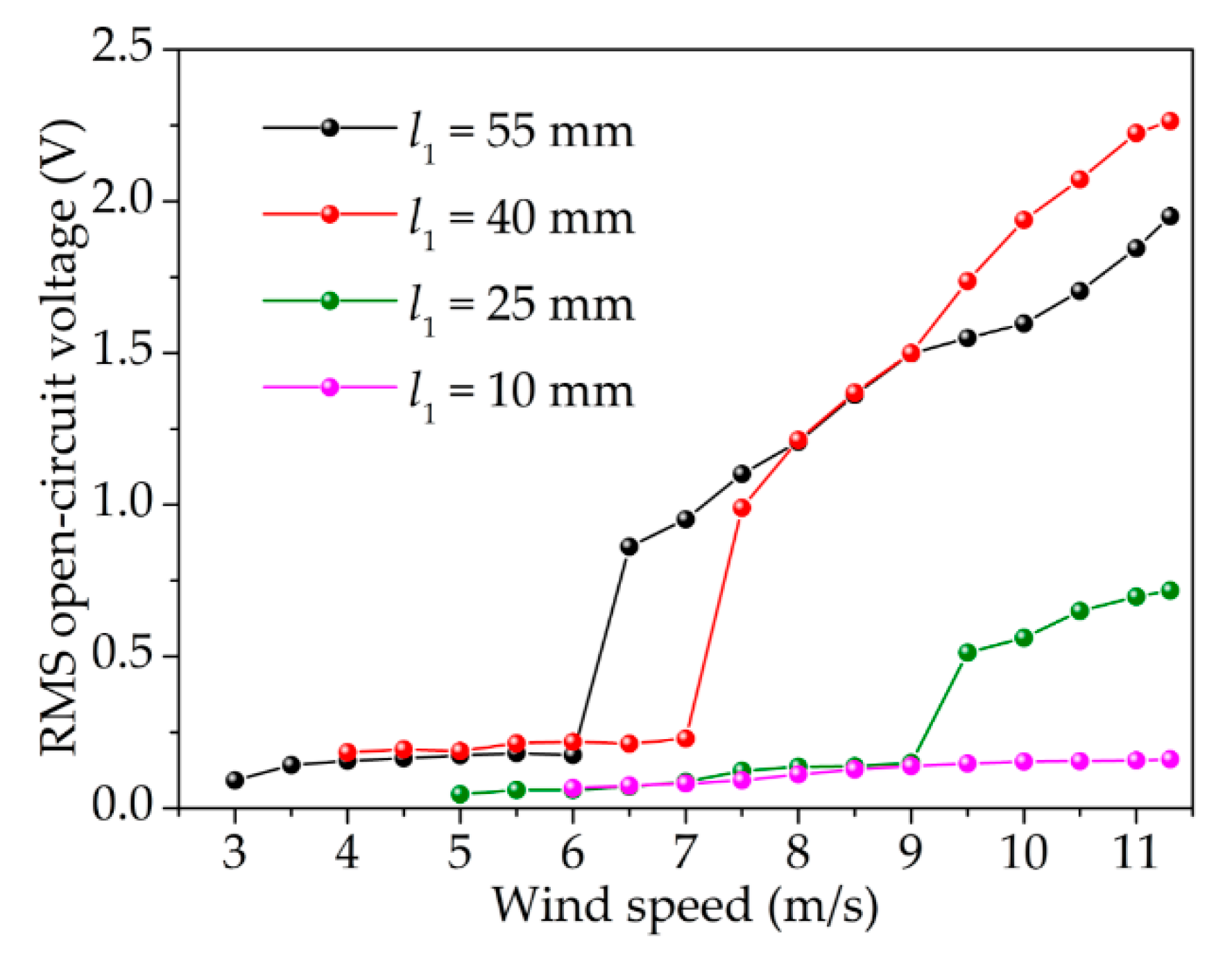
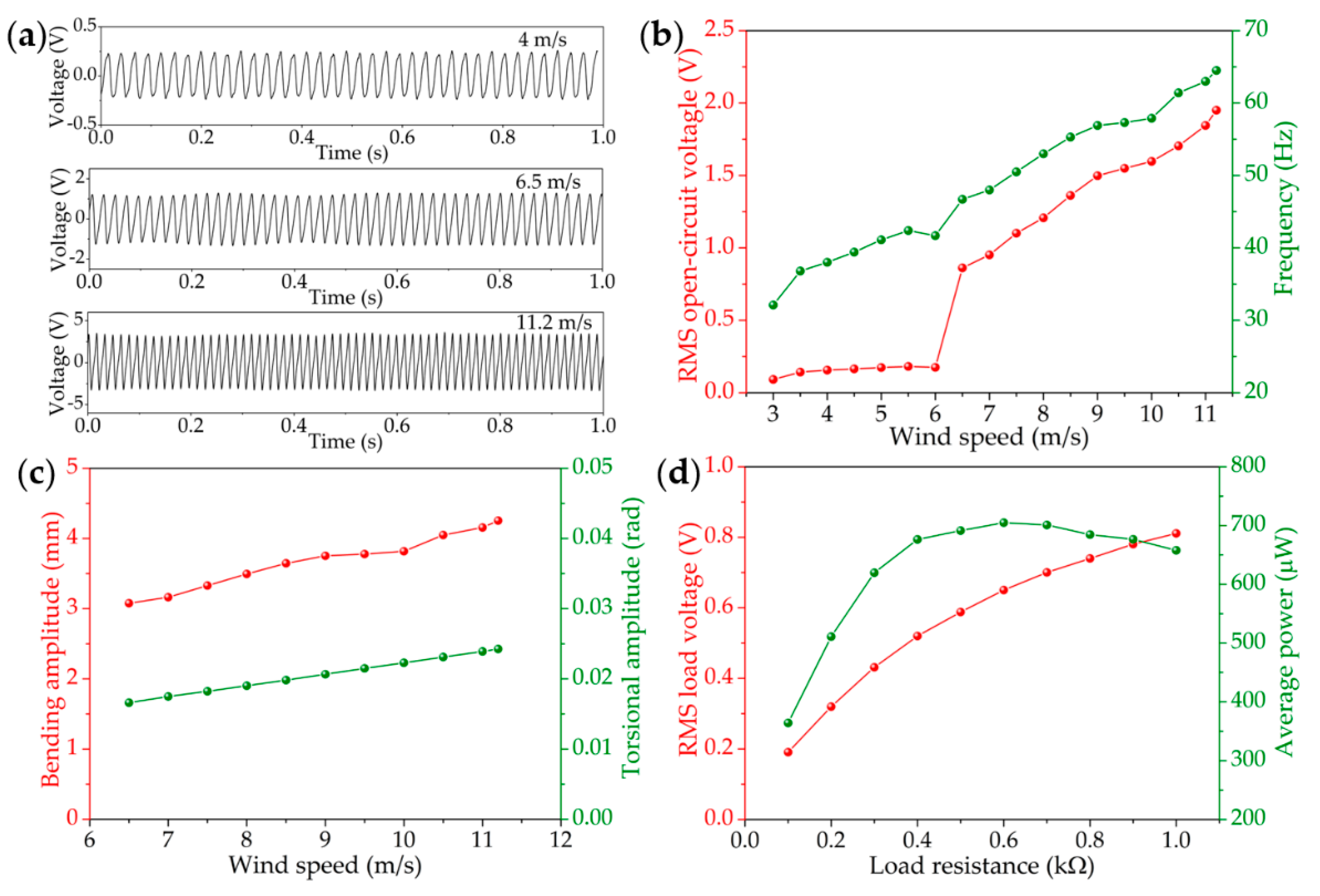
4. Experimental Results

To experimentally verify the predictions of the analytical model and investigate the output performance of the proposed energy harvester, a small wind tunnel with wind speeds ranging from 0 m/s to 11.2 m/s was built. Wind speed was measured using an anemometer (KIMO (Bordeaux, France) CTV100), and the waveform of voltage and the corresponding frequency were recorded by an oscilloscope (KESIGHT (Santa Rosa, CA, USA) InfiniiVision DSO-X 2012A) with a 10 MΩ probe. Energy harvesters with four positions of magnets were tested in the wind tunnel. Figure 4 shows the relationship between the root-mean square (RMS) open-circuit voltage and the wind speed of energy harvesters with four positions of magnets. The voltage increased sharply at wind speeds of 6.5 m/s, 7.5 m/s, and 9.5 m/s, when l1 was 55 mm, 40 mm, and 25 mm, respectively. These wind speeds can be seen as the critical wind speeds of the wind belts. As shown in Table 5, the results agreed well with analytical predictions. Therefore, the proposed analytical model can be used for the prediction of the critical wind speed of the wind belt type energy harvester. Besides, the experimental results also show that an energy harvester with magnets near the middle of the PET membrane can achieve a higher output. In a word, placing magnets near the center of the membrane can further reduce the critical wind speed and subsequently improve output performance.
Since the energy harvester with central magnets has the lowest critical wind speed and considerable output performance, it was further investigated. Figure 5a shows the open-circuit voltage waveform at different wind speeds. The energy harvester can generate a steady output, indicating that it vibrated with constant amplitude. Figure 5b shows the RMS open-circuit voltage and the corresponding frequency at different wind speeds. When wind speed was below 3 m/s, there was no output, because the wind belt did not vibrate. When the wind speed reached 3 m/s, the wind belt vibrated with a small amplitude and the energy harvester was able to output small voltage. This phenomenon comes mainly from the asymmetry of the pre-stress along the y direction, so a torsional vibration with torsional axis deviating from the central axis could be observed. When the wind speed reached 6.5 m/s, violent vibration of the wind belt took place and the energy harvester was able to output an RMS voltage of 0.86 V. As the wind speed continues to increase, the voltage of the energy harvester increased approximately linearly; when the wind speed reached 11.2 m/s, the energy harvester generated an output voltage of 1.95 V. Meanwhile, the frequency of the voltage can be used to represent the flutter frequency of the wind belt. We can see that the flutter frequency increased with the wind speed, which was mainly due to enhancement of nonlinearity as the bending amplitude increased. Figure 5c shows the derived bending and torsional amplitudes at different wind speeds according to the nonlinear Equations (38) and (39). The bending and torsional amplitudes increased with the wind speed as well as the flutter frequency, which can explain why the voltage increased with wind speed. To obtain the maximum output power and the corresponding optimized load, the RMS voltage Urms with different load resistance was measured. Average power can be gained according to the equation P a v e = U r m s 2 / R l . Figure 5d shows the measured RMS load voltage and the derived average power as a function of load resistance; at wind speed of 10 m/s, the energy harvester can generate a maximum average power of 705 μW with an optimized load resistance of 600 Ω. The result highlights application prospects for the power supply of low-power electronic devices.

5. Conclusions

The wind belt type energy harvester has been proven to harvest wind energy and convert it to electric power. In this paper, an analytical model for kinetic analysis of a flutter-based wind energy harvester was proposed. The modal analysis of the analytical model was found to be in agreement with that of finite element simulation. The flutter analysis indicates that flutter at low wind speeds mainly comes from the first bending and torsional modes. The critical wind speeds calculated by the analytical model were consistent with the previous empirical formulae and the experimental results. The results also suggest that a wind energy harvester with magnets close to the center of the membrane has better performance. The optimized wind energy harvester can output a maximum average power of 705 μW at wind speed of 10 m/s., offering application prospects for the power supply of low-power electric devices. The analytical model presented in this work has significance for the structural design and performance improvement of a flutter-based electromagnetic wind energy harvester. It can also provide a reference for the theoretical analysis of other aerodynamic devices. However, the vibration of the wind belt may come from the coupling of multiple effects, which need further investigation.

Author Contributions

Z.L. carried out the analytical model and designed the experiments; Q.W. and Z.W. provided funding and experimental facilities; Z.L. wrote the paper; Q.W., X.H. and Z.W. revised the paper.

Funding

This work was supported by the National Natural Science Foundation of China (61604023).

Conflicts of Interest

The authors declare no conflict of interest.

References

  1. Shaikh, F.K.; Zeadally, S. Energy harvesting in wireless sensor networks: A comprehensive review. Renew. Sustain. Energy Rev. 2016, 55, 1041–1054. [Google Scholar] [CrossRef]
  2. Salauddin, M.; Toyabur, R.M.; Maharjan, P. High performance human-induced vibration driven hybrid energy harvester for powering portable electronics. Nano Energy 2018, 45, 236–246. [Google Scholar] [CrossRef]
  3. Nasiri, A.; Zabalawi, S.A.; Jeutter, D.C. A linear permanent magnet generator for powering implanted electronic devices. IEEE Trans. Power Electron. 2011, 26, 192–199. [Google Scholar] [CrossRef]
  4. Tan, Y.S.; Dong, Y.; Wang, X.H. Review of MEMS electromagnetic vibration energy harvester. J. Microelectromech. Syst. 2016, 26, 1–16. [Google Scholar] [CrossRef]
  5. Orrego, S.; Shoele, K.; Ruas, A.; Doran, K.; Cagiano, B.; Mittal, R.; Kang, S.H. Harvesting ambient wind energy with an inverted piezoelectric flag. Appl. Energy 2017, 194, 212–222. [Google Scholar] [CrossRef]
  6. Bogue, R. Energy harvesting: A review of recent developments. Sens. Rev. 2015, 35, 1–5. [Google Scholar] [CrossRef]
  7. Liu, H.C.; Zhong, J.W.; Lee, C.K.; Lee, S.W.; Lin, L.W. A comprehensive review on piezoelectric energy harvesting technology: Materials, mechanisms, and applications. Appl. Phys. Rev. 2018, 5, 041306. [Google Scholar] [CrossRef]
  8. Elahi, H.; Eugeni, M.; Caudenzi, P. A review on mechanisms for piezoelectric-based energy harvesters. Energies 2018, 11, 1850. [Google Scholar] [CrossRef]
  9. Usharani, R.; Uma, G.; Ummpathy, M.; Choi, S. A novel piezoelectric energy harvester using a multi-stepped beam with rectangular cavities. Appl. Sci. 2018, 8, 2091. [Google Scholar] [CrossRef]
  10. Mccarthy, J.M.; Watkins, S.; Deivasigamani, A.; John, S.J. Fluttering energy harvesters in the wind: A review. J. Sound Vib. 2016, 361, 355–377. [Google Scholar] [CrossRef]
  11. Hu, Y.L.; Yang, B.; Chen, X.; Wang, X.L.; Liu, J.Q. Modeling and experimental study of a piezoelectric energy harvester from vortex shedding-induced vibration. Energy Convers. Manag. 2018, 162, 145–158. [Google Scholar] [CrossRef]
  12. Kumar, S.K.; Bose, C.; Ali, S.F.; Sarkar, S.; Gupta, S. Investigations on a vortex induced vibration based energy harvester. Appl. Phys. Lett. 2017, 111, 243903. [Google Scholar] [CrossRef]
  13. Dai, H.L.; Abdelkefi, A.; Yang, Y.; Wang, L. Orientation of bluff body for designing efficient energy harvesters from vortex induced vibrations. Appl. Phys. Lett. 2016, 108, 053902. [Google Scholar] [CrossRef]
  14. Ewere, F.; Wang, G. Performance of galloping piezoelectric energy harvesters. J. Intell. Mater. Syst. Struct. 2014, 25, 1693–1704. [Google Scholar] [CrossRef]
  15. Hemon, P.; Amandolese, X.; Andrianne, T. Energy harvesting from galloping of prisms: A wind tunnel experiment. J. Fluids Struct. 2017, 70, 390–402. [Google Scholar] [CrossRef]
  16. Li, X.T.; Lyu, Z.; Kou, J.Q.; Zhang, W.W. Mode competition in galloping of a square cylinder at low Reynolds number. J. Fluid Mech. 2019, 867, 516–555. [Google Scholar] [CrossRef]
  17. Chen, Y.; Mu, X.J.; Wang, T.; Ren, W.W.; Yang, Y.; Wang, Z.L.; Sun, C.L.; Gu, A.Y.D. Flutter Phenomenon in Flow Driven Energy Harvester—A Unified Theoretical Model for “Stiff” and “Flexible” Materials. Sci. Rep. 2016, 6, 35180. [Google Scholar] [CrossRef] [PubMed]
  18. Bao, C.Y.; Dai, Y.T.; Wang, P.; Tang, G.J. A piezoelectric energy harvesting scheme based on stall flutter of airfoil section. Eur. J. Mech. B Fluids 2019, 75, 119–132. [Google Scholar] [CrossRef]
  19. He, X.F.; Yang, X.K.; Jiang, S.L. Enhancement of wind energy harvesting by interaction between vortex-induced vibration and galloping. Appl. Phys. Lett. 2018, 112, 033901. [Google Scholar] [CrossRef]
  20. Li, S.G.; Lipson, H. Vertical-stalk flapping-leaf generator for wind energy harvesting. In Proceedings of the Conference on Smart Materials, Adaptive Structures and Intelligent Systems, Oxnard, CA, USA, 20–24 September 2009; 2, pp. 611–619. [Google Scholar] [CrossRef]
  21. Available online: http://www.humdingerwind.com (accessed on 27 June 2019).
  22. Frayne, S.M. Fluid-Induced Energy Converter with Curved Parts. U.S. Patent 20080297119A1, 4 December 2008. [Google Scholar]
  23. Frayne, S.M. Generator Utilizing Fluid-Induced Oscillations. U.S. Patent 7,573,143, 11 August 2009. [Google Scholar]
  24. Fei, F.; Mai, J.D.; Li, W.J. A wind-flutter energy converter for powering wireless sensors. Sens. Actuators A Phys. 2012, 173, 163–171. [Google Scholar] [CrossRef]
  25. Quy, V.D.; Sy, N.V.; Hung, D.T.; Huy, V.Q. Wind tunnel and initial field tests of a micro generator powered by fluid-induced flutter. Energy Sustain. Dev. 2016, 33, 75–83. [Google Scholar]
  26. Aquino, A.I.; Calautit, J.K.; Hughes, B.R. A Study on the Wind-Induced Flutter Energy Harvester (WIFEH) Integration into Buildings. Energy Procedia 2017, 142, 321–327. [Google Scholar] [CrossRef]
  27. Aquino, A.I.; Calautit, J.K.; Hughes, B.R. Integration of aero-elastic belt into the built environment for low-energy wind harnessing: Current status and a case study. Energy Convers. Manag. 2017, 149, 830–850. [Google Scholar] [CrossRef]
  28. Pan, C.T.; Liu, Z.H.; Chen, Y.C.; Liu, C.F. Design and fabrication of flexible piezo-microgenerator by depositing ZnO thin films on PET substrates. Sens. Actuators A Phys. 2010, 159, 96–104. [Google Scholar] [CrossRef]
  29. Pan, C.T.; Liu, Z.H.; Chen, Y.C. Study of broad bandwidth vibrational energy harvesting system with optimum thickness of PET substrate. Curr. Appl. Phys. 2012, 12, 684–696. [Google Scholar] [CrossRef]
  30. Foong, F.M.; Thein, C.K.; Ooi, B.L.; Yurchenko, D. Increased power output of an electromagnetic vibration energy harvester through anti-phase resonance. Mech. Syst. Signal Process. 2019, 116, 129–145. [Google Scholar] [CrossRef]
  31. He, X.M.; Wen, Q.; Lu, Z. A micro-electromechanical systems based vibration energy harvester with aluminum nitride piezoelectric thin film deposited by pulsed direct-current magnetron sputtering. Appl. Energy 2018, 228, 881–890. [Google Scholar] [CrossRef]
  32. Theodorsen, T. General theory of aerodynamic instability and the mechanism of flutter. NACA Tech. Rep. 1935, 496, 1–23. [Google Scholar]
  33. Fung, Y.C. A Introduction to Theory of Aeroelasticity; Dover Publications: New York, NY, USA, 1993; pp. 214–215. [Google Scholar]
  34. Van der Put, M. Rigidity of Structures Against Aerodynamic Forces; IABSE: Zurich, Switzerland, 1976. [Google Scholar]
  35. Selberg, A.; Hjort-Hansen, E. The fate of flat plate aerodynamics in the world of bridge decks. In Proceedings of the Theodorsen Colloquium, Trondheim, Norway, 1976; pp. 101–113. [Google Scholar]
Figure 1. Schematic diagram of the flutter-based electromagnetic energy harvester.
Applsci 09 04823 g001
Figure 2. (ac) The first three bending vibration modes, and (df) the first three torsional vibration modes by finite element simulation. The (g) bending and (h) torsional vibration modes by the derived analytical model.
Applsci 09 04823 g002
Figure 3. (a) The diverging rate as a function of wind speed when all the first three bending and torsional modes are involved in the calculation. (b) The diverging rate as a function of wind speed when the first, second, and third bending and torsional modes are involved in the calculation, respectively. (c) The diverging rate as a function of wind speed when there is no magnet attached to the PET membrane. (d) The relationship between the critical wind speed and the structural damping ratio.
Applsci 09 04823 g003
Figure 4. The RMS open-circuit voltage of energy harvester with different magnets positions.
Applsci 09 04823 g004
Figure 5. (a) The open-circuit voltage waveform at different wind speeds. (b) The RMS open-circuit voltage and the corresponding frequency as a function of wind speed. (c) The relationship between the derived bending and torsional amplitudes, and wind speed. (d) The RMS load voltage and derived average power as a function of load resistance at wind speed of 10 m/s.
Applsci 09 04823 g005
Table 1. Material and structural parameters of the device.
ParameterDescriptionValue
EpYoung’s modulus of PET membrane2.4 GPa [28,29]
ρpDensity of PET membrane1400 kg/m3 [28,29]
νpPoisson’s ratio of PET membrane0.36 [28,29]
l × 2b × tpDimension of PET membrane130 mm × 20 mm × 0.18 mm
EmYoung’s modulus of magnet160 GPa
ρmDensity of magnet7500 kg/m3
νmPoisson’s ratio of magnet0.3
l2 × 2b × tmDimension of magnet20 mm × 20 mm × 1 mm
Φ1 × Φ2 × hInner diameter, external diameter, and thickness of coils3 mm × 27 mm × 6 mm
NTurns of coils5310
RcResistance of coils580 Ω
d0Gap between magnets and coils14 mm
Table 2. The bending and torsional natural frequencies by finite element simulation and the derived analytical model.
Natural Frequency (Hz)Bending ModeTorsional Mode
1st Mode2nd Mode3rd Mode1st Mode2nd Mode3rd Mode
ANSYS FEM3.8323.3284.1113.46164.71166.04
Analytical model3.7122.7780.7113.54162.50163.83
Error (%)3.132.364.040.591.341.33
Table 3. The comparison of critical wind speed by different equations when there is no magnet attached to the PET membrane.
EquationsVan der PutSelbergThis Work
Critical wind speed (m/s)8.607.437.67
Table 4. Predictions of the critical wind speed of an energy harvester with different magnet positions.
Magnets Locationsl1 = 55 mml1 = 40 mml1 = 25 mml1 = 10 mm
Critical wind speed (m/s)6.467.319.9410.13
Table 5. Comparison of critical wind speed between the analytical predictions and the experimental results.
Critical Wind Speed (m/s)l1 = 55 mml1 = 40 mml1 = 25 mm
Analytical model6.467.319.94
Experimental results6.57.59.5

