Abstract
Crack propagation produced by frost heave affects the durability of slab-track structures in high-humidity and cold regions in China. This work is intended to reveal the evolution laws of frost-heave crack propagation, establish evaluation criteria for crack propagation, and investigate factors involved in frost-heave crack propagation. Firstly, by preparing slab-track specimens with initial cracks, an experiment of frost-heave crack propagation was designed. The process of frost-heave crack propagation was carried out by means of digital image correlation (DIC) technology and acoustic emission (AE) technology, respectively. These experiments revealed the evolution laws of generalized strain and AE events’ location during crack initiation and propagation, respectively, and the key parameters of micro-crack initiation strain and unstable propagation strain were obtained. By using theoretical and experimental analysis, a double-strain criterion for frost-heave crack propagation was proposed. Finally, factors involved in frost-heave crack propagation were investigated. The results show that crack initiation can be reflected by the crack-tip strain. The average micro-crack initiation strain and unstable propagation strain were found to be 224 με and 243 με, respectively. Moreover, it was found that the frost-heave crack propagation was caused by an ice plug which formed at the crack opening. When the crack width is larger than 2.7 mm and the external temperature is lower than −6.6 °C, cracks propagate easily under the frost-heave force.
1. Introduction
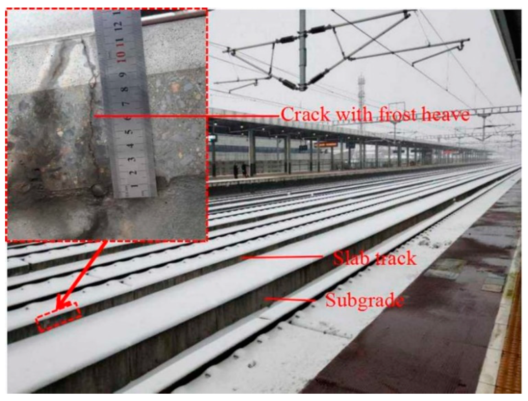
High-speed railway track systems mainly adopt slab-track structures, which has been widely used in China, Japan, Germany, etc. [1]. However, large-scale slab-tracks laying across different climatic regions have suffered from inappropriate design and insufficient construction. Therefore, various crack damages have appeared in slab-track structures due to the combined action of train loads and complex environmental loads. In cold areas in particular, if water intrudes into slab-track cracks, the frost-heave force caused by the water–ice phase transition accelerates crack propagation [2]. In China, there is more than 5000 km of high-speed railway track in cold regions with a design speed of up to 350 km/h [3]. When frost-heave crack propagation occurs, the amount of maintenance work required increases drastically and the durability of slab-tracks is reduced. Therefore, maintenance measures have been put forward for different crack widths (d) in the “Maintenance Rules for Slab Track Lines of High-Speed Railway (Trial Implementation 2012)” [4]. However, the effect of frost-heave force on crack propagation in cold regions is equivocal. Therefore, this maintenance standard did not consider the influence of external temperature (T) and moisture content on crack propagation. Consequently, it is of great significance to reveal the evolution laws of frost-heave crack propagation, establish reasonable evaluation criteria for the crack-propagation state, and provide important theoretical and experimental support for crack maintenance and the prevention of the frost-heaving of slab-track. Slab-track cracks with frost-heave are shown in Figure 1.
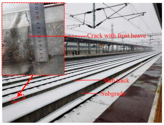
Figure 1.
Slab-track cracks with frost heave.
Research on frost-heave crack propagation has mainly concentrated on the mechanism of frost heave and the value of the frost-heave force in cracks. Gong [5] analyzed the mechanisms of frost damage to concrete pore structures using ultrasonic nondestructive testing, image analysis, and scanning electron microscopy. Qin [6] investigated the types of damage to slabs under the effect of static ice pressure, and clarified the mechanism of frost-heave damage using a theoretical model. It is generally acknowledged that the frost-heave force produced by the water–ice phase transition causes cracks to propagate [7]. However, there have been very few studies regarding evaluation criteria for frost-heave crack propagation in slab tracks. In recent years, the mileage of slab-track has been increasing steadily in China. Investigation of crack damage to slab-tracks in cold areas of China has found that cracks with a width of 0.2~0.4 mm have appeared in the supporting layer (base slab) of slab-track, and the maximum width of cracks can reach 2 mm. Cracks with a width of 0.1~0.2 mm have appeared on the surface of the slab-track, 80% of which are transverse penetrating cracks [8,9,10]. In areas of severe cold and high humidity, once crack damage occurs in a slab-track structure, the cracks will inevitably experience frost heave [7]. Considering the disadvantages of cracks for the durability of slab-tracks, scholars have conducted in-depth research on the factors involved in frost-heave crack propagation. For example, the moisture content in cracks, the width of cracks, and temperature are all significant factors that affect frost heave. As the temperature decreases and the moisture content in cracks increases, the speed of frost-heave crack propagation will accelerate [11,12,13,14,15]. In spite of the mounting effort that is being put into the topic, the timing of crack propagation, the state of cracks, and the law of crack propagation under the influence of external factors are still not exactly known. In order to evaluate the state of crack propagation and reveal the evolution laws of frost-heave crack propagation, many theoretical studies have been conducted on the value of the frost-heave force [16,17]. Additionally, some researchers have experimentally measured the frost-heave force in cracks [18,19], and proposed the use of stress intensity factors at the crack tip as the criterion for the initiation of concrete cracks. The value of the stress-intensity factor at the crack tip depends not only on the magnitude of the external load on the crack, but also on the magnitude of crack cohesion. Additionally, initiation toughness is also controlled by the crack initiation load and the equivalent length of the crack. However, the value of the frost-heave force measured by different test methods differs greatly. The reason for this may be that the small size of crack tips makes it difficult to implant pressure sensors.
With the advancement of monitoring technology, the testing methods for damage to concrete structures have been constantly improved. Commonly used methods are X-ray techniques [20,21], computational tomography (CT) [22,23,24], ultrasonic tomography [25,26], etc. X-ray methods are an effective technique for accurately showing the level of cracking but have limitations associated with expensive equipment. In addition, long-term use of X-rays can cause serious side effects on the human body. CT scanning techniques have the advantages of non-destructive, dynamic, quantitative detection, high-resolution digital image display, etc. However, the method requires complex software for analysis. Although ultrasonic tomography can achieve general evaluation of concrete structure damage, and can not fully reveal the structural micro-crack extension state. In general, there are deficiencies in the whole process of monitoring concrete crack propagation.
The most commonly used techniques to examine the process of concrete crack propagation are acoustic emission (AE) and digital image correlation (DIC) [27]. AE are the stress waves caused by the rapid release of energy within the concrete structure due to the elastic deformation and crack growth of the material itself when the concrete structure is subject to external force or internal force [28,29]. AE are commonly related to concrete structural damage. Thus, AE can evaluate the whole process of the concrete structure cracking [30,31]. However, it is sometimes difficult to establish a quantitative relationship with the crack propagation parameters of concrete structures. In addition, the evolution of strain is the macro-performance of concrete material in the process of fracture [32]. DIC recognizes the surface of the measuring concrete structure in digital camera images and allocates coordinates to the image pixels. The first image of the concrete structure represents the undeformed state. After or during the deformation of the concrete structure, extra images are recorded. Then, the computing system compares the digital images and calculates the displacement and deformation of the concrete structural characteristics [33,34]. Therefore, DIC technology overcomes the disadvantage of traditional strain gauges, i.e., that they cannot accurately identify the position of crack initiation and the crack propagation path [35]. An effective experimental method for obtaining the process of concrete cracks propagation is by comparing AE and DIC. The strain parameters obtained by DIC can be quantitatively linked to the crack propagation stage. Therefore, it is necessary to study the law of frost-heave crack propagation by revealing the strain evolution at the crack tip and establishing the strain criterion of the frost-heave crack propagation.
Based on DIC and AE technology, in this study, the process of frost-heave crack propagation in concrete specimens was studied respectively. An evolution law of generalized strain (ε) and AE events location on the surface of the specimens during frost-heave crack propagation is revealed. The validity of applying surface strain to study frost-heave crack propagation is verified by comparing two experimental results. Then, based on linear elastic fracture mechanics and traditional strength theory, a double-strain criterion for frost-heave crack propagation is proposed. Furthermore, the proposed double-strain criterion is successfully applied to study the influence of different factors on the propagation state of cracks. The research results provide important theoretical and experimental support for crack maintenance and the prevention of frost-heave in slab-tracks in cold areas.
2. Experimental Program
2.1. Specimen and Equipment Preparation
A mold was designed and manufactured with a length, width, and height of 300 mm, 150 mm, and 150 mm, respectively. This mold was then used to prepare concrete specimens. Initial cracks were made in the concrete specimens using a steel piece. The mixing proportion and performance indicators of the track-slab concrete are listed in Table 1, according to the requirement in the “Code for the Design of High-Speed Railway (TB10621-2014)” [36].

Table 1.
Mixing proportion and performance indicators of the track-slab concrete specimen.
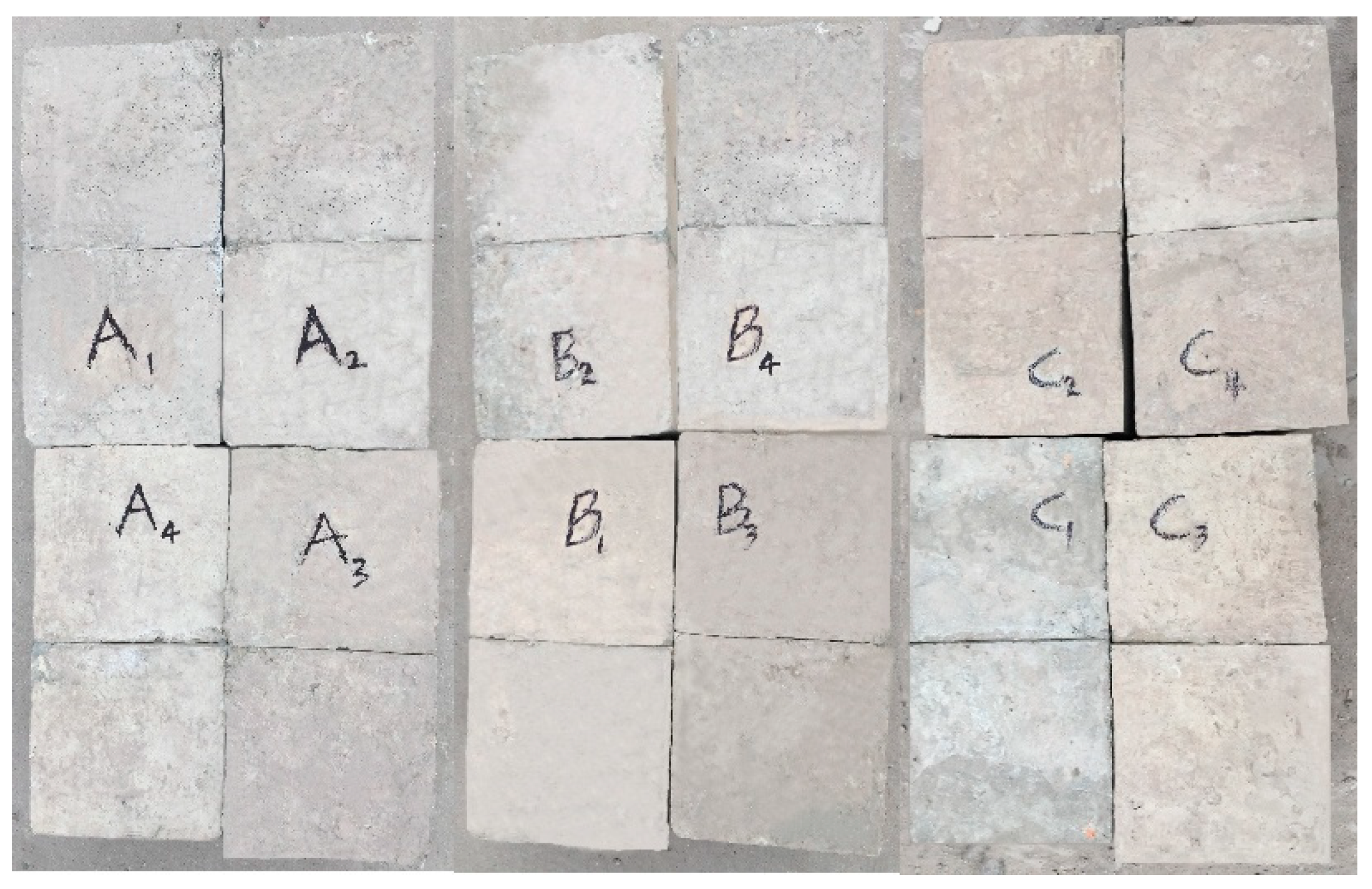
In order to pull out the steel piece conveniently, the surface of the steel sheet was coated with an adequate amount of lubricating oil. Fix the steel piece in the mold. Then, the concrete was cast according to the mixing proportion. After casting for 10 h, the steel piece was pulled out and cured in standard conditions. The main process for specimen fabrication included stirring, vibrating, pulling out the steel piece, demolding, and maintenance [37]. The specimens with the initial crack are shown in Figure 2.
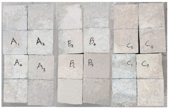
Figure 2.
Specimens with initial crack.
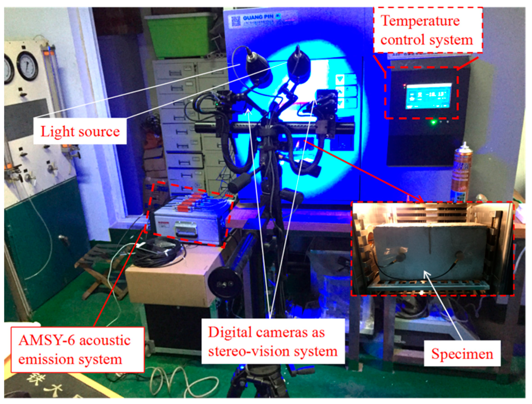
Figure 3 describes the experimental set-up for testing the evolution of generalized strain and AE events location on the surface of the specimens during the process of crack initiation and propagation. Non-contact optical testing equipment was used to monitor the surface strain field of the specimens. At the same time, acoustic emission damage location technology was used to monitor the AE events location on the surface of the specimens. The environmental temperature was controlled by an environmental box with an adjustable temperature range of −40~150 °C.
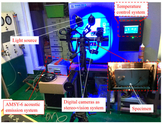
Figure 3.
Experimental set-up.
A control variable method was employed in this experiment. The specimens were divided into three groups—group A, group B, and group C—in order to study the effect of crack width, external temperature, and crack moisture content, respectively. At least three parallel tests were carried out in each group. Test conditions and specimen parameters are shown in Table 2.

Table 2.
Test conditions and specimen parameters for tests of frost-heave crack propagation.
2.2. Description of the Experimental Method
2.2.1. Digital Image Correlation (DIC) Method and Instrumentation
DIC is a computer vision-based data analysis program that uses mathematically related methods to analyze digital images of specimens undergoing deformation and has been widely used in various applications. Compared with the conventional technology, DIC has the advantage of continuously measuring spatial displacement and full field strain [34,35]. It was necessary to prepare the concrete specimens before the DIC testing. Firstly, dirt and dust was removed from the surface of the specimens. Additionally, speckle marks were sprayed onto the outer surface of the concrete specimens, as shown in Figure 4a. The camera was calibrated before the start of the strain measurement test. 90 × 72 mm calibration plate was used in this test.

Figure 4.
Specimen preparation. (a) Speckles applied to the outer surface of the specimen; (b) arrangement of acoustic emission sensor.
For the testing of generalized strain at the crack tip, the speckles on the surfaces of the specimens were identified by DIC technology. The displacement field of the specimens was obtained by image matching before and after deformation. The correlation coefficient C related to the image gray level is expressed as follows:
where f(x,y) is the gray level of the reference coordinate points; is the average gray level of the reference sub-domain; g(x’,y’) is the gray level of the coordinate points (x’,y’) on the target map; and is the average gray level of the target sub-region. By matching points in the calculating area of the two images before and after deformation, the change in the position of the relevant points and the change in the displacement field distribution in the measuring range can be obtained. The displacement field was derived using the least squares method, and thus the generalized strain field distribution in the measuring area was obtained.
2.2.2. Acoustic Emission (AE) Method and Instrumentation
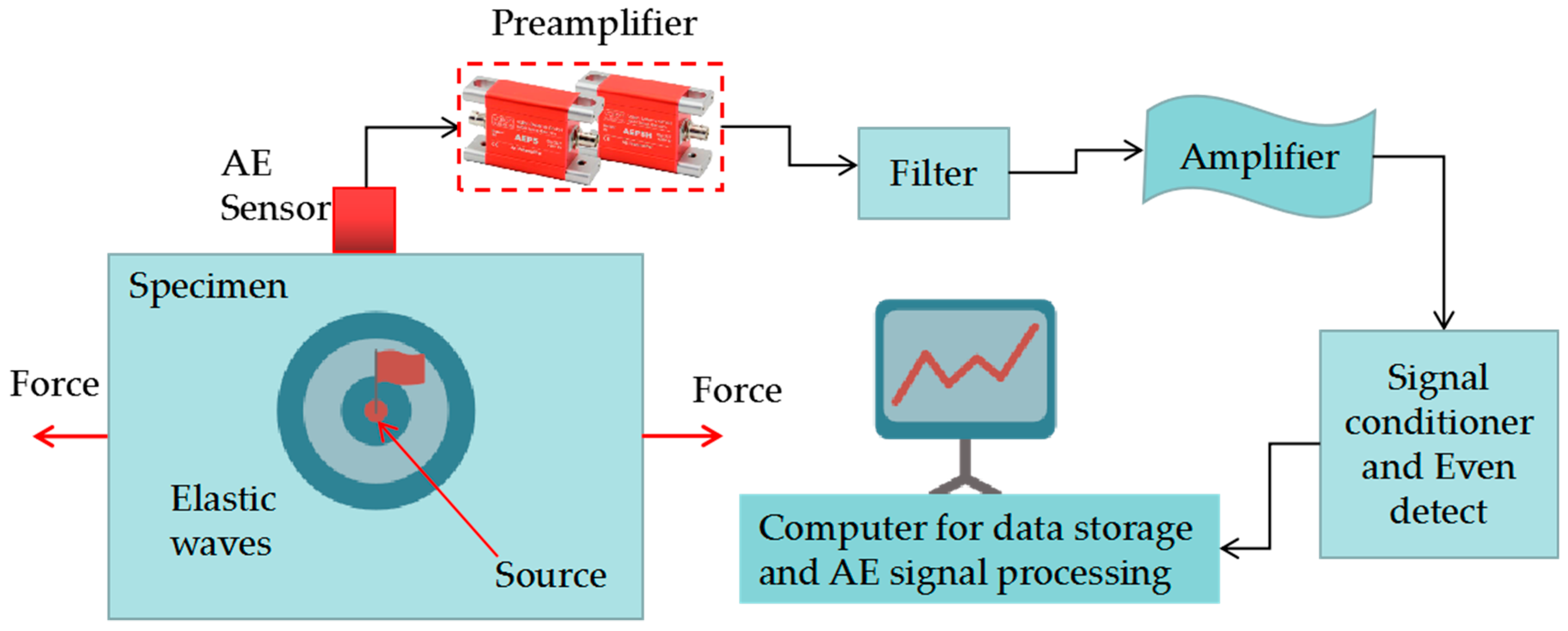
Acoustic emission (AE) are the stress waves caused by the rapid release of energy within the material due to the elastic deformation and crack growth of the material itself when the material is subject to external force or internal force [28]. Generally, stress waves have low amplitude and high frequencies in the ultrasonic range. Therefore, very sensitive piezoelectric sensors are needed to capture them. The AE method was displayed in Figure 5. Commonly, AE is a good tool to study the fracture evolution process of materials, which can continuously monitor in real time the generation and propagation of micro-cracks in materials under the action of loads [29,30,31].
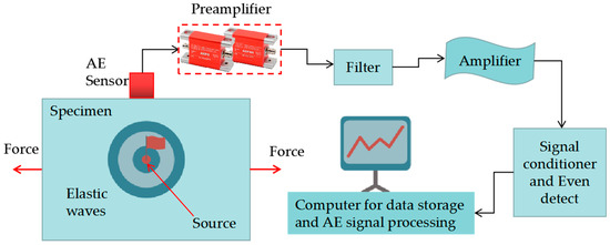
Figure 5.
Acoustic emission (AE) method.
AE signals were acquired with an AMSY-6 system (Figure 3) from Vallen Systeme GmbH equipment by using VS45-H sensors (with sensitivity within the frequency band 20–450 kHz), which were placed on the specimen as showed in Figure 4b. For waveform recording, the sampling frequency of 2.0 MHz was used, and 2048 data were stored per each signal. Thus, the pretrigger was established at 200 samples. The threshold was set at 40 dB and 34 dB AEP5 gain preamplifier was used for each channel. Digital filters in the frequency range 25–850 kHz were used during acquisition in order to reject undesirable low and high frequency noise. According to the average rising time of the multiple pencil lead break signals received by the sensor, the peak definition time (PDT) = 100 μs was determined, then the hit definition time (HDT) = 200 μs and the hit lockout time (HLT) = 300 μs were determined. The wave velocity of the signals in concrete materials was 4500 m/s.
3. Results and Discussion
3.1. Determination of the Frost-Heave Crack Propagation Law
3.1.1. Frost-Heave Crack Propagation Process
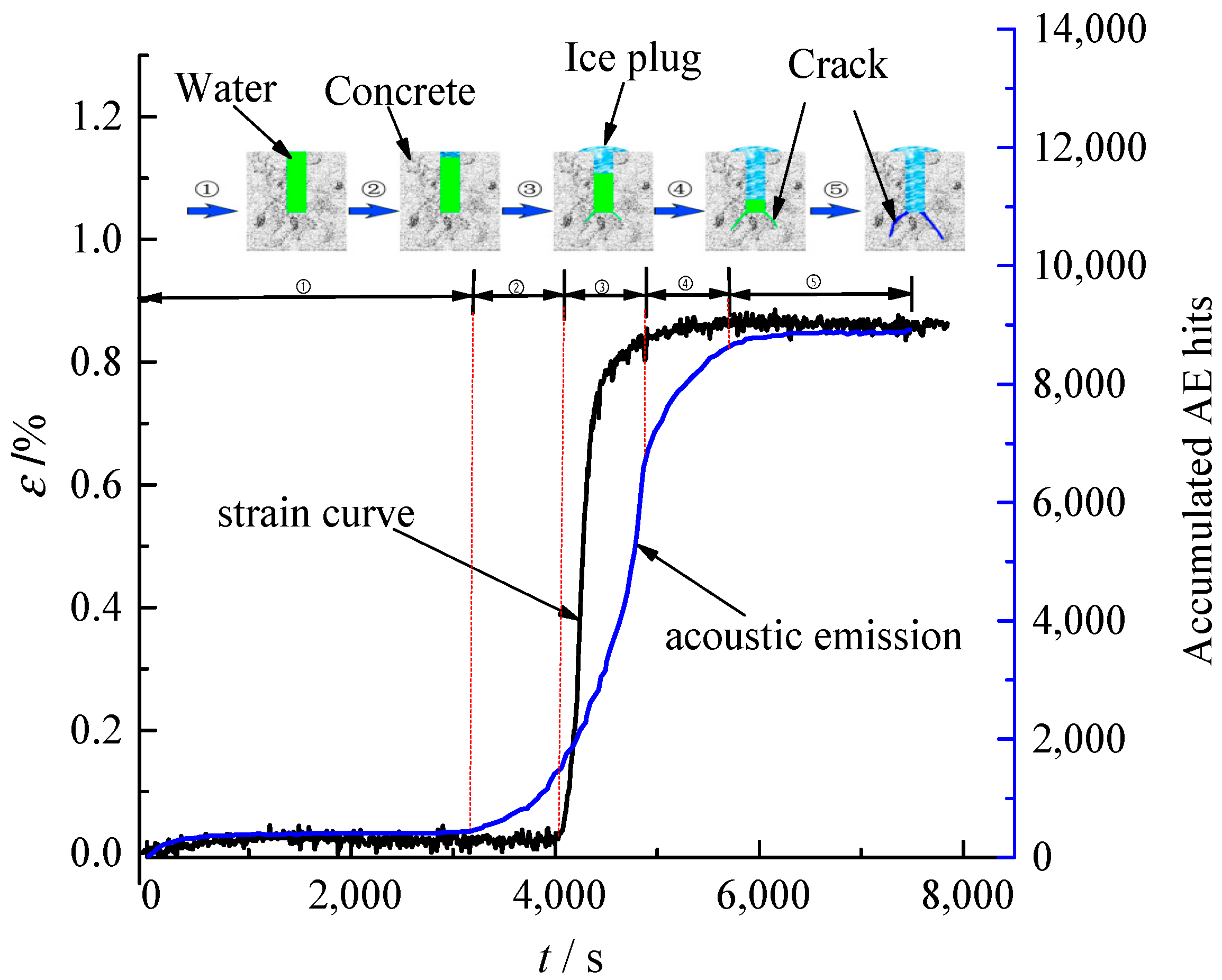
The evolution process of the generalized strain curve and accumulated AE hits curve is shown in Figure 6. The time between micro-crack initiation and unstable propagation is very short, and no detailed analysis is made in this section; however, it will be discussed in Section 3.1.2 by analyzing the key parameters of micro-crack initiation strain and unstable propagation strain. According to the change in slope of the two curves, the process of frost-heave crack propagation was divided into five stages, as shown in Figure 6. As can be seen from the figure, in the first stage of the freezing process, the generalized strain at the crack tips of the concrete specimens increases slightly and the accumulated AE hits is small. At this stage, the damage to the concrete is mainly caused by micro-cracks which form at the crack tip, which is the reason for the lower acoustic emissions.
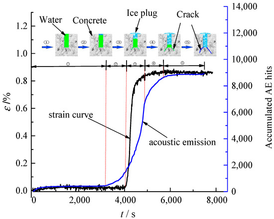
Figure 6.
Schematic diagram of the process of frost-heave crack propagation for specimen A1.
When the cooling process reaches the second stage (see Figure 6), the slope of the accumulated AE hits curve increases; this occurs before the abrupt change in the slope of the generalized strain curve. At this stage, a small amount of water in the crack underwent a water–ice phase transition, and a small amount of energy release was detected. As a result, the slope of the accumulated AE hits curve increases gradually. However, at this stage, the mass of iced water does not form an ice plug at the crack opening, and the frost-heave force is not sufficient to cause crack propagation. Thus, the slope of the generalized strain curve does not change significantly.
As the temperature continues to decrease, the generalized strain at the crack tip and the number of accumulated AE hits increase abruptly when the third stage (Figure 6) is reached. These phenomena indicate that the water–ice phase transition which occurs in the cracks and the formation of the ice plug at the crack opening result in an abrupt increase of frost-heave water pressure at the crack tip. The catastrophe point of the generalized strain curve represents unstable crack propagation. The accumulated energy is released in the form of acoustic emissions and, accordingly, the accumulated AE hits curve shows an abrupt increase in slope. Therefore, cracks propagate under the frost-heave force during this stage.
When the cooling process reaches the fourth stage (Figure 6), the slope of the generalized strain curve decreases, and the count of accumulated AE hits increases slowly. This stage occurs after the abrupt changes of generalized strain at the crack tip. Due to the propagation of cracks in the third stage, the frost-heave force in the cracks is released. The unreleased frost-heave force in the cracks is insufficient to cause the main cracks to continue to propagate significantly.
When the cooling reaches the fifth stage (Figure 6), the generalized strain at the crack tip tends to be stable, and the number of accumulated AE hits remains almost unchanged, which indicates that the water–ice phase transition has been completed and the final equilibrium state has been reached.
The evolution law of generalized strain is in good agreement with the micro-damage of the crack tip, which verifies the correctness of using surface strain at the crack tip to study the frost-heave propagation process of cracks.
3.1.2. Crack Frost-Heave Propagation Process AE and DIC Comparison
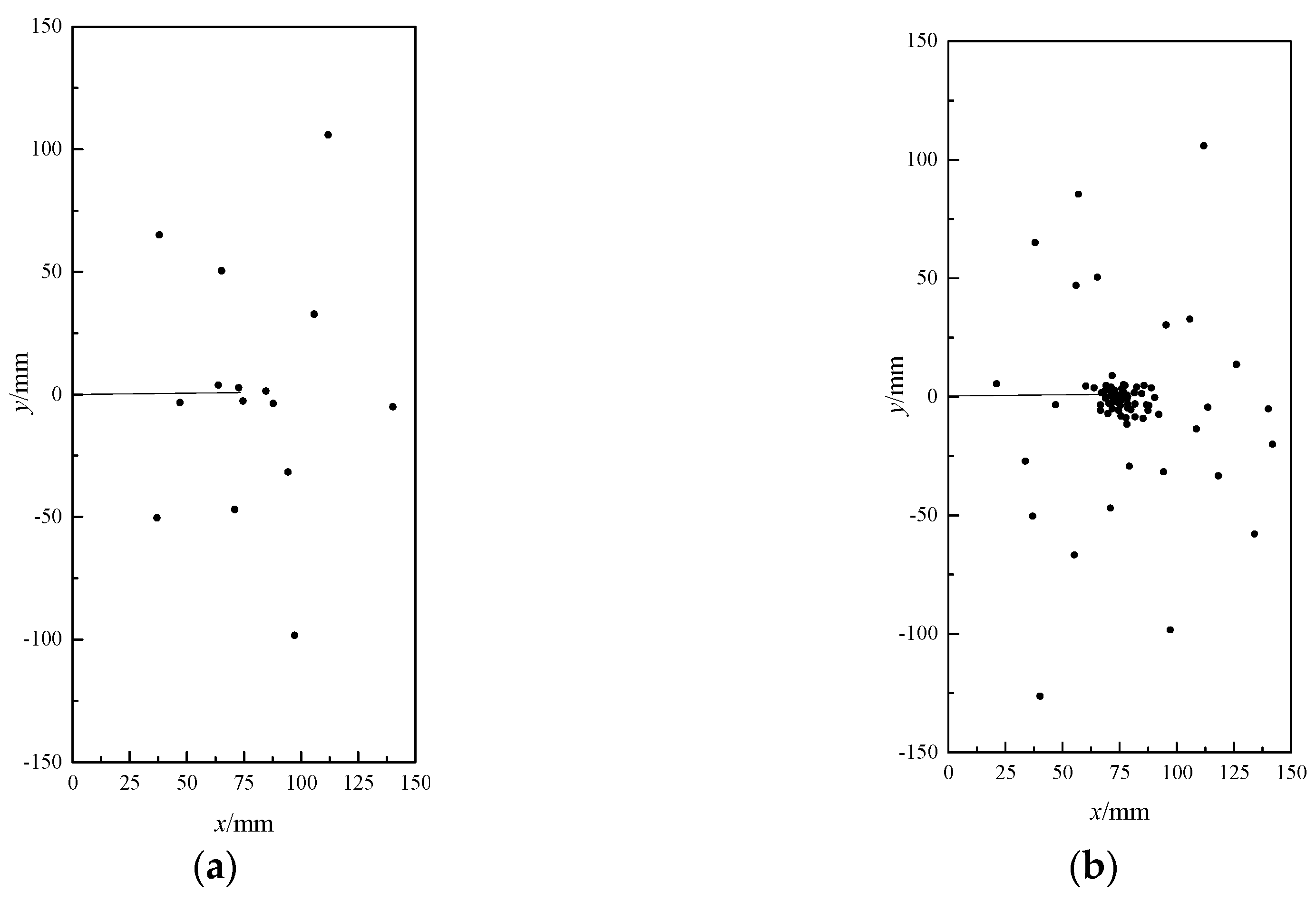
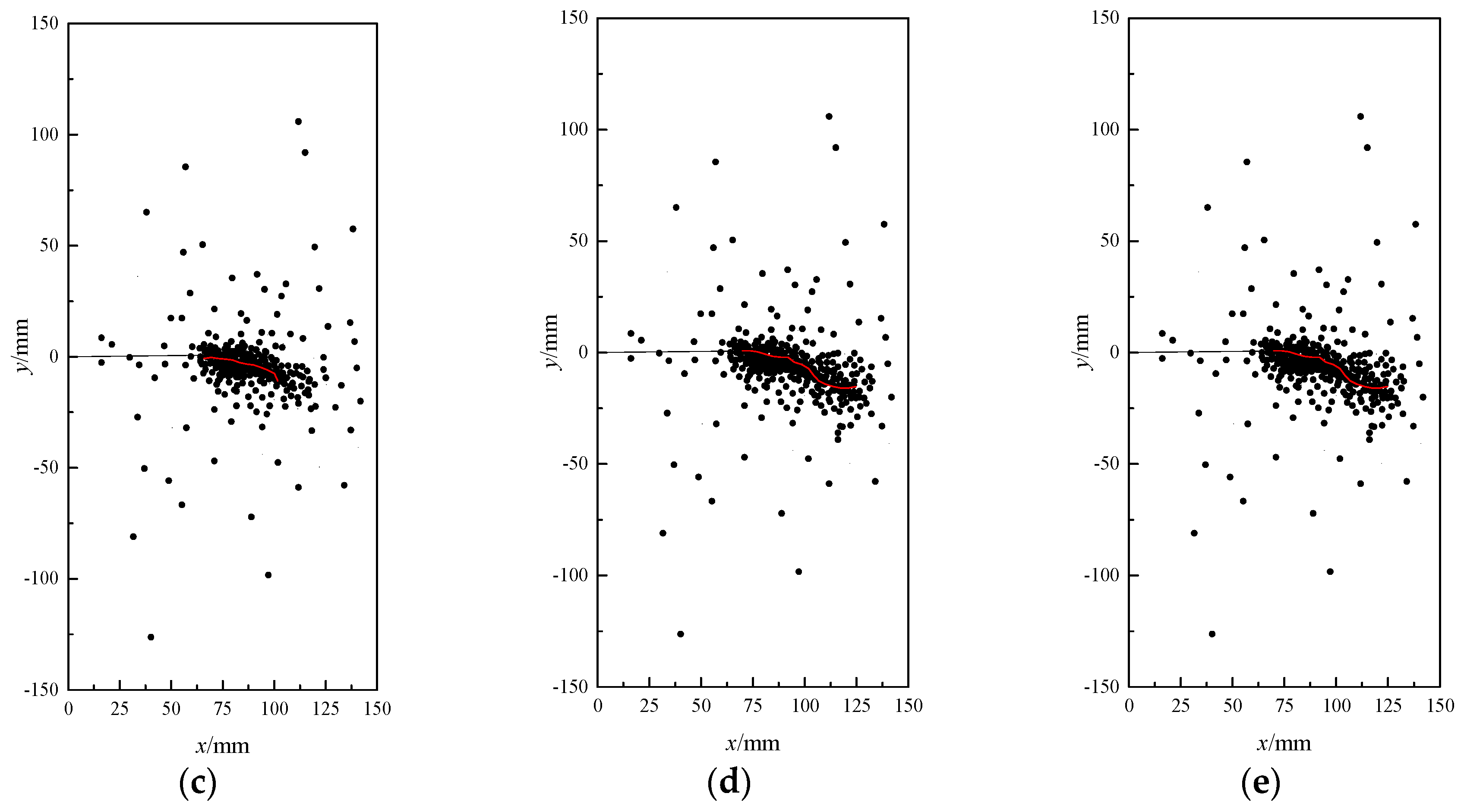
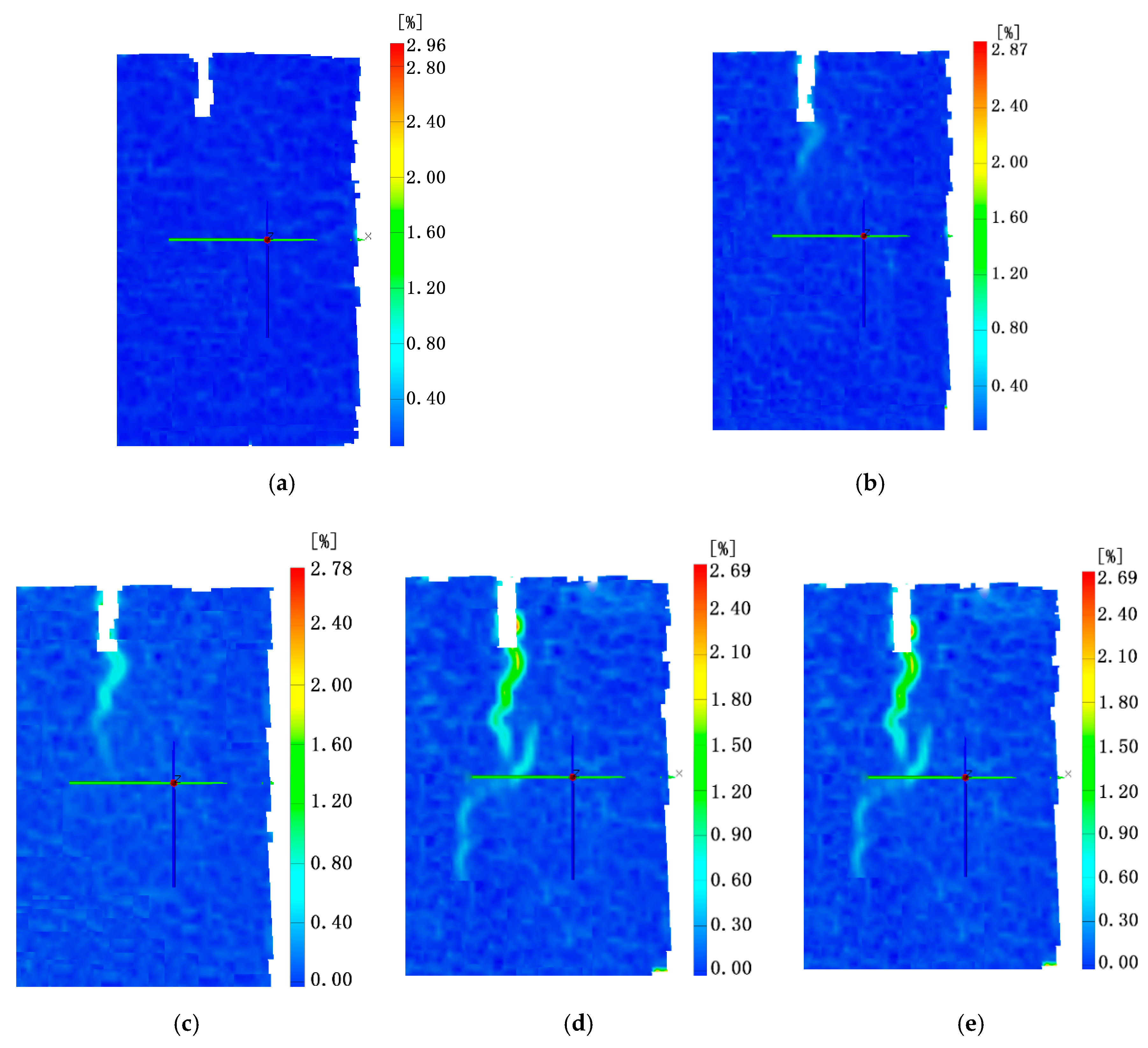
The purpose of this section is to compare the AE and DIC results under the same test conditions for more convincingly verify the correctness of using the crack tip surface strain to study the frost-heave crack propagation process. Due to space limitations, this subsection presents, in detail, only the AE and DIC results of test specimens with ID A1. According to the five stages of the crack cracking process in Section 3.1.1, the AE location and DIC results at different stages of the cracking process is illustrated in Figure 7 and Figure 8.
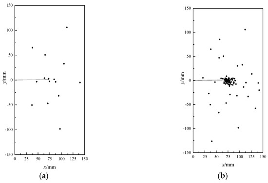
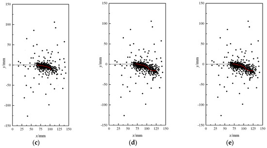
Figure 7.
Testing results of AE events location during crack frost-heave propagation. (a) Less and scattered, stage 1; (b) concentrated the tip of initial crack, stage 2; (c) densely distributed along the initial crack direction, stage 3; (d) the distribution extends slightly, stage 4; (e) unchanged distribution, stage 5.
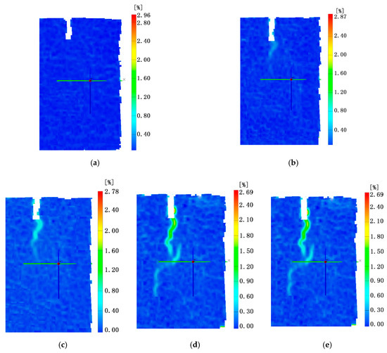
Figure 8.
Surface strain distribution during crack frost-heave propagation. (a) The process of temperature equilibrium, stage 1; (b) micro-crack formation, stage 2; (c) obvious crack, stage t3; (d) freezing force release, stage 4; (e) frost heave completed, stage 5.
As can be seen from the Figure 7a, after the first stage of the frost-heaving process, the AE localization event on the surface of the specimen is very small and scattered. The acoustic emission events generated at this stage are mainly caused by the original defects and micro-cracks in the specimen during the temperature equilibrium process. It can be observed in Figure 8a that the surface strain field of the specimen that no obvious crack propagation appears on the surface of the specimen.
After the second stage, AE localization events (Figure 7b) begin to concentrate in the initial crack region. As can be seen in Figure 8b, micro-cracks gradually form at the tip of the initial crack, which indicates that initial cracks begin to affect the surface strain field of the specimen, and a small number of micro-cracks are generated at this stage.
The temperature decreases, the specimen undergoes a third stage, which is the stage of ice plug formation at the initial crack opening. The surface AE localization event of the specimen (Figure 7c) is densely distributed along the initial crack direction. The surface strains field of the specimen (Figure 8c) suddenly shows obvious crack propagation, and the crack propagates along the direction of the initial crack. This indicates that the frost-heave force in the crack suddenly increases due to the formation of ice plug at the opening of the initial crack, which causes the crack to propagate.
After the fourth stage, the surface AE localization event of the specimen (Figure 7d) continues to extend slightly along the direction of crack propagation. The surface strain field results of the specimen (Figure 8d) show that the main crack propagation direction is slightly offset. The reason for the analysis is that there are a large number of randomly distributed coarse particles in the concrete structure. The crack encounters coarse aggregate blocking during the propagation process. The crack propagation direction circulates along the surface of the coarse aggregate.
3.1.3. Mechanism of Frost-Heave Crack Propagation
The experimental results indicate that the effect of the frost-heave force produced by the water–ice phase transition in cracks should not be ignored. These results were combined with the experimental results of the frost-heave crack propagation process. The general mechanism of frost-heave damage to the slab-track with water cracking can be summarized as follows: a micro-frost-heave force is produced at the crack tip at the initial freezing stage. This force is balanced with temperature stress for a period of time. With decreasing temperature, an ice plug is formed at the crack opening. The frost-heave water pressure abruptly increases in the crack, breaking the balance between the frost-heave force and temperature stress. When the frost-heave force reaches the crack initiation threshold of concrete, the generalized strain abruptly increases around the crack tip. The crack propagates and then the crack volume increases, resulting in the release of the frost-heave water pressure in cracks. With the further decrease of temperature, the water–ice phase transition is completed. Therefore, the main cause of frost-heave damage to the slab-track with cracked water is the frost-heave force caused by the water–ice phase transition in cracks.
3.2. Determination of the Crack Initiation Criterion Based on Strain
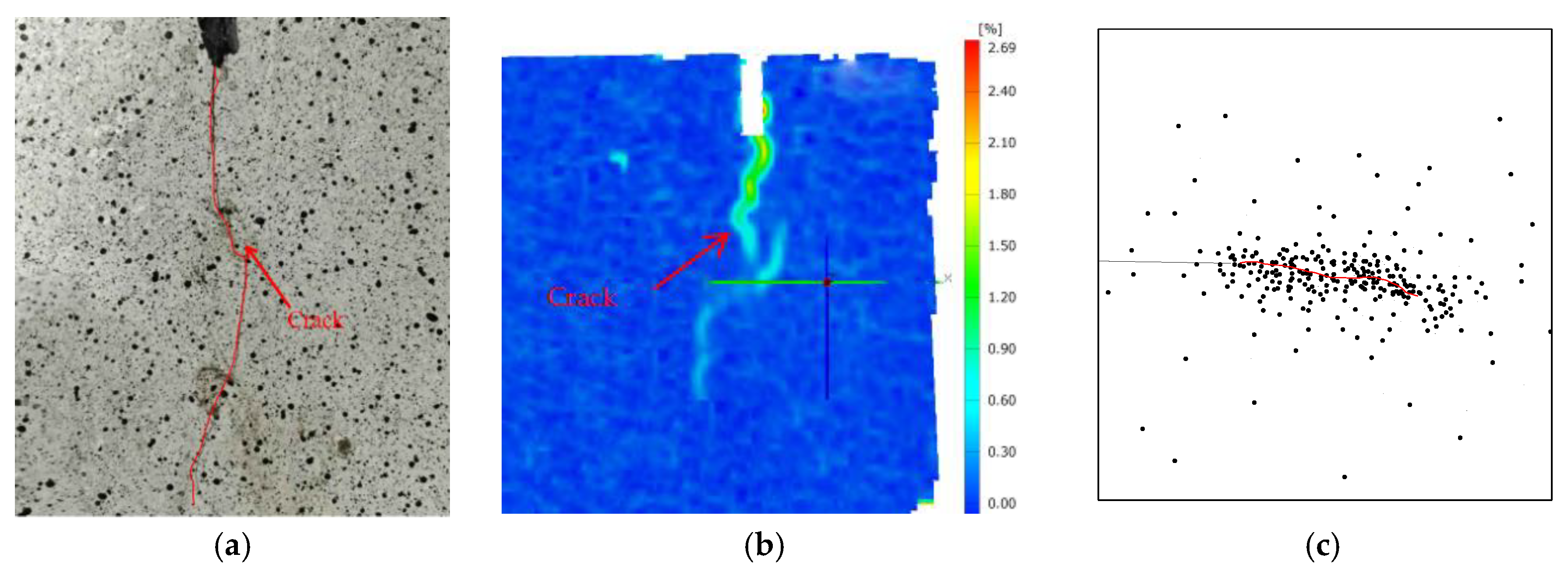
The research results described in Section 3.1 show that the frost-heave propagation of cracks can be studied by measuring the strain at the crack tip. In this section, theoretical analysis of crack growth based on this strain is carried out. The crack propagation of a specimen after the experiment is shown in Figure 9a. From this figure, it can be seen that the initial crack extends vertically, which conforms to the characteristics of a mode I crack propagation. Figure 9b illustrates the full field of the surface strain distribution by means of the DIC technique. From this figure, it can be seen that the range of main tensile strain on the surface of the concrete specimens is distributed along the crack tip. The AE localization event on the surface of the specimen is shown in Figure 9c. It can be seen that AE localization event is densely distributed along the initial crack direction. For more detail see Section 3.1.2. Comparing Figure 9a–c, it is found that the process of frost-heave crack propagation can be determined according to the principal tensile strain, which is of profound significance for crack prevention and the monitoring of concrete structures. As concrete is a typical quasi-brittle material, the propagation progress of cracks can be subdivided into micro-crack initiation, stable propagation, and unstable propagation [38,39]. An accurate and applicable crack propagation criterion is essential in the analysis of concrete fracture processes. Most of the existing research uses parameters such as cracking toughness, maximum tensile stress, and stress intensity factor at the crack tip to determine the crack propagation state [40,41,42,43]. The value of the stress-intensity factor at the crack tip depends not only on the magnitude of the external load on the crack, but also on the magnitude of crack cohesion. Additionally, initiation toughness is also controlled by the crack initiation load and the equivalent length of the crack. The value of the frost-heave force measured by different test methods differs greatly [18,19]. Therefore, the application of the existing theory of the analysis of frost-heave crack propagation process has certain deficiencies. Therefore, there is an urgent need to establish a strain model in order to evaluate the crack-propagation state under frost heave.
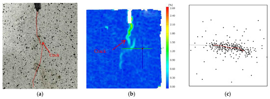
Figure 9.
Crack propagation. (a) Crack propagation on specimen surface; (b) generalized strain distribution on specimen surface; (c) AE events location on specimen surface.
3.2.1. Double-Strain Criterion of Crack Propagation
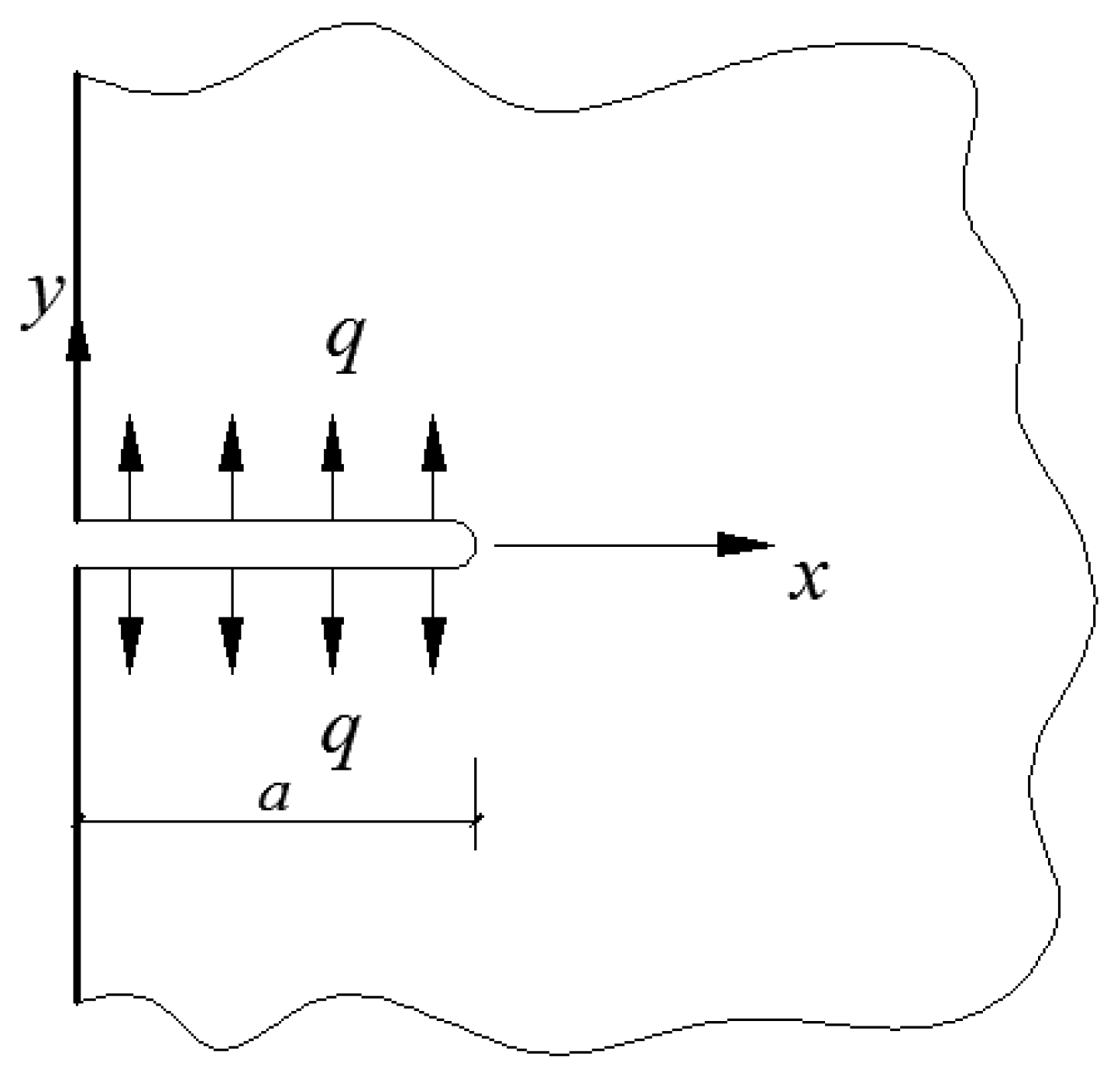
Comparing Figure 9a–c, it can be seen that frost-heave crack propagation is in accordance with the characteristics of a mode I crack propagation. Additionally, the crack width is much smaller than the specimen length. Therefore, the specimen was simplified by a plane model, as shown in Figure 10. There is an edge crack with a length of a on the half plane, and an approximately uniformly distributed frost-heave force q was assumed for the cracks. The model has ox symmetry. Therefore, only the first quadrant was studied.
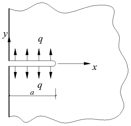
Figure 10.
Frost-heave force model of crack.
Before the micro-cracks start to propagate, the stress field at the crack tip can be analyzed according to the linear elastic fracture mechanics, and the principal stress field distribution at the crack tip is obtained.
The boundary conditions of the model are as follows:
Since , all stress components tend to zero. The stress intensity factor at the crack tip [44] is expressed as follows:
For a type I crack, the stress field near the tip is as follows:
where r and θ are the polar coordinates; σx, σy, and τx are the stress components near the crack tip; and KI is the stress intensity factor at the crack tip.
The principal stress near the crack tip was obtained using the following equations:
where σ1, σ2, and σ3 are the principal stresses and ν is Poisson’s ratio.
Using the solution of the elastic stress field at the crack tip, the critical length of the micro-crack initiation zone which is at the crack tip under unified strength as the yield criterion is analyzed.
The unified strength theory of concrete [45] takes into account the difference between the tensile and compressive properties of materials and the influence of intermediate principal stress. Therefore, in this study, the unified strength theory of concrete was taken as the failure criterion of concrete. The mathematical expression of the unified strength theory [46] is as follows:
where α is the ratio of the tensile and compressive strength of the concrete materials; σs is the ultimate stress of the material; [σt] is the allowable stress for the material; and b is a parameter used to reflect the influence of external force on the failure of the material, which is given as follows:
where τ0 is the shear strength of the material, and the range of parameter b is 0 ≤ b ≤ 1.
In the process of solving the boundary equation of the micro-crack generation zone at the crack tip under plane strain, since σ3 ≠ 0, it is necessary to judge the magnitude relationship between the two principal stresses σ2 and σ3.
When σ2 = σ3 in Equation (7), Equation (9) can be obtained as follows:
When Equation (6) is equal to Equation (7), we can obtain θ1 as follows:
θ0 > θ1 can be obtained by comparing Equation (9) with Equation (10).
When 0 ≤ θ ≤ θ1, σ1 > σ2 > σ3, and , by introducing Equation (5) into Equation (7), the boundary expression of the crack initiation zone at the crack tip can be obtained as follows:
Figure 9 indicates that cracks propagate along the x-axis. Letting θ = 0° and KI = KIC in Equation (11), the critical length of the micro-crack initiation zone at the crack tip on the x-axis can be obtained as follows:
where KIC is the fracture toughness of the material and rcu0 is the critical length of micro-crack initiation at the crack tip when θ = 0°.
The critical length of the micro-crack initiation zone at the crack tip will be determined by the equivalent tensile strain theory.
According to the principle of material mechanics for plane strain problems, the generalized Hooke’s law can be expressed as follows:
where ε1, ε2, and ε3 are the principal strains and E is the Young’s modulus of elasticity of the material.
By introducing Equation (5) into Equation (13), the principal strain field at the crack tip under the plane strain problem can be obtained:
Figure 9 shows that the frost-heave crack propagation belongs to mode I. In this study, only the tension state of the concrete cracks is discussed, so ε1 ≥ 0, ε2 ≥ 0, and θ ≤ θ1.
where εe is the equivalent strain and < > is a function which expresses the following meanings:
The boundary equation expression of the micro-crack zone at the crack tip is obtained as follows:
Letting θ = 0° and KI = KIC in Equation (17), the critical length of the micro-crack initiation zone at the crack tip on the x-axis can be obtained as follows:
where [εe] is the crack initiation strain threshold and r0 is the critical length of micro-crack initiation at the crack tip when θ = 0°.
When the crack initiation, the critical length of the micro-crack zone at the crack tip obtained from the equivalent strain theory is equal to the critical length obtained from the unified strength theory of concrete. Let Equation (12) be equal to Equation (18). The strain threshold of micro-crack initiation under the plane strain state can be obtained as follows:
When the concrete material is determined, the parameters α, ν, E and σs in Equation (19) are constant, so [εe] can be used as the criterion for crack initiation. [εe] is represented by εini.
The theoretical relationship between the micro-crack initiation strain and unstable propagation strain Equation (19) during the propagation process is established. Reference [38] indicates that the maximum yield strain could be used as the critical state for the unstable propagation of concrete cracks. The yield strain is represented by εun. Due to the limited level of strain testing in previous studies, the initiation stage of micro-cracks was often not observed. As concrete is a typical quasi-brittle material, the propagation progress of cracks can be subdivided into micro-crack initiation, stable propagation, and unstable propagation. In this paper, it is suggested that the crack-propagation state of concrete can be judged by two double-strain fracture parameters—micro-crack initiation strain εini and unstable strain εun. The double-strain model of frost-heave crack propagation can be described as follows:
When the strain at the crack tip ε ≤ εini, there is a stable micro-crack zone at the crack tip;
When the strain at the crack tip εini <ε ≤ εun, the micro-crack at the crack tip propagates steadily without macro-cracking.
When the strain at the crack tip εun < ε, macro-cracks emerged and continued to propagate in an unstable state.
3.2.2. Experimental Verification of the Double-Strain Criterion
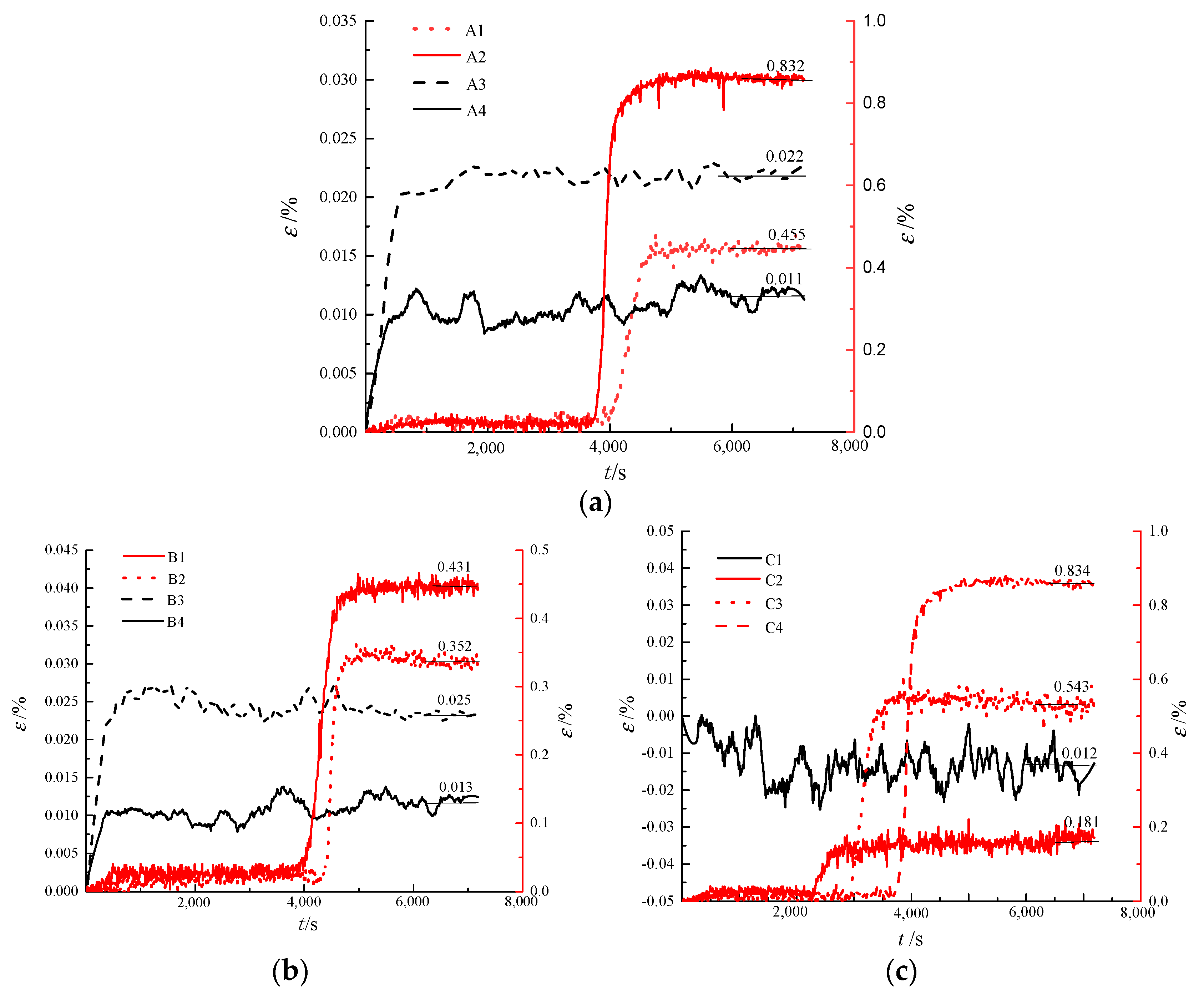
The evolution curve of the generalized strain of the crack tip for different crack widths, different external temperatures, and different initial moisture contents, during the cooling time, is shown in Figure 11.
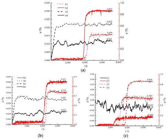
Figure 11.
The evolution of generalized strain at the crack tip. (a) Different crack widths; (b) different external temperatures; (c) different initial moisture contents.
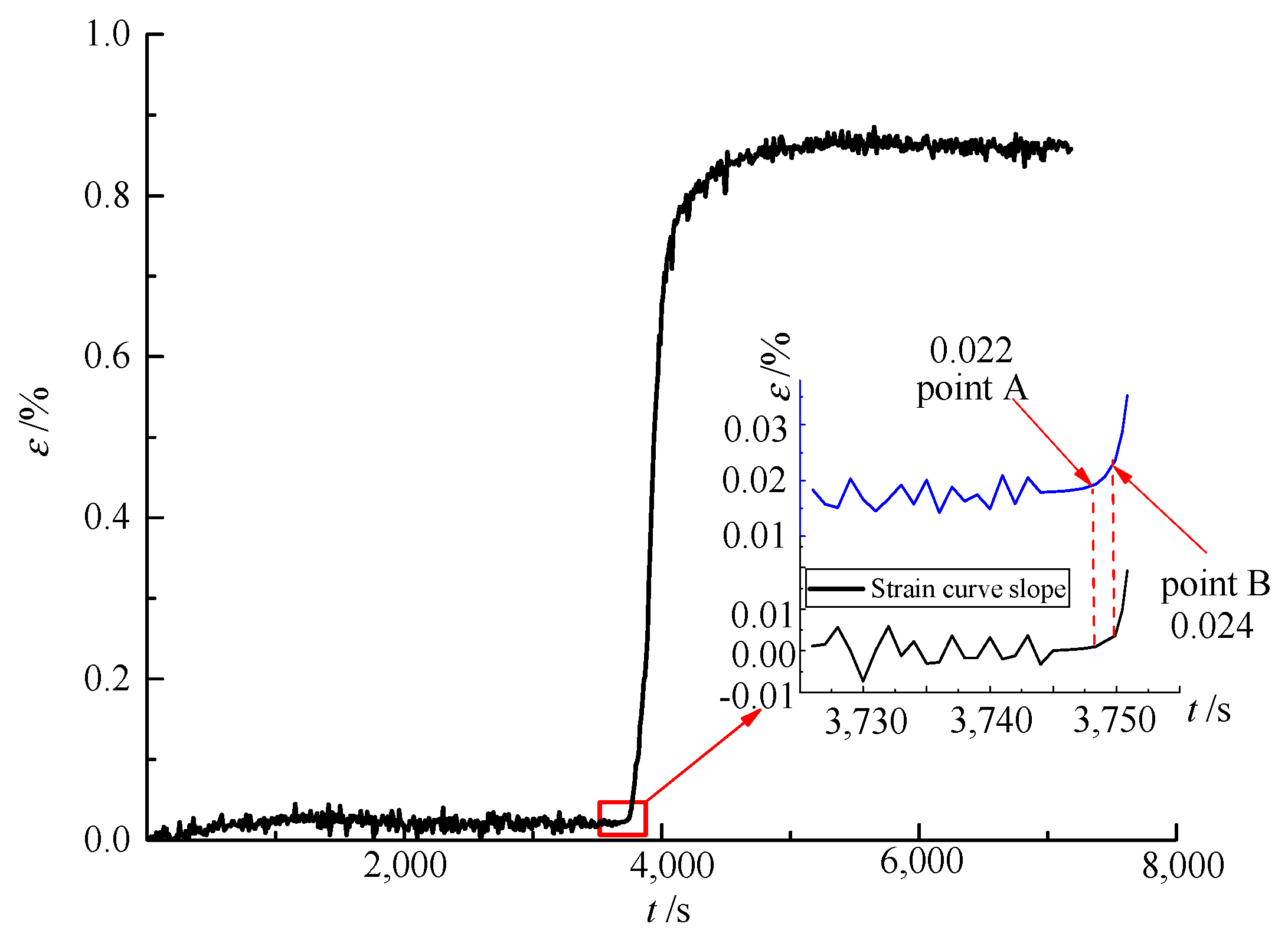
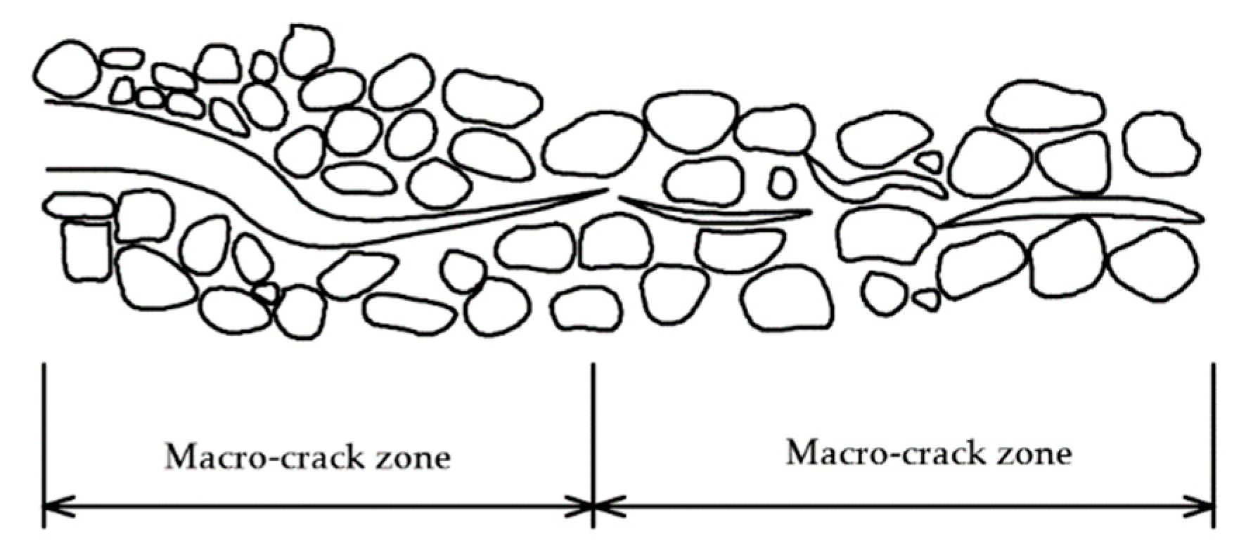
From Figure 11, it can be seen that the cracks in specimens A1, A2, B1, B2, C2, C3, and C4 propagated under frost heave. Crack-tip strain of specimens A3, A4, B3, B4, C4 produces slight changes during temperature equilibrium. Taking specimen of A1 as an example, the generalized strain evolution curve in the process of frost-heave crack propagation was analyzed, as shown in Figure 12. From the figure, it can be seen that the slope of the generalized strain curve at point A begins to increase, which represents the frost-heave initiation of micro-cracking. By this time, the concrete in the micro-crack zone had become a loose discontinuous medium, as shown in Figure 13, but could still able to withstand stress. With increasing micro-crack deformation, the stress transferred by the micro-cracks decreases until it finally forms macro-cracks, as shown in Figure 13. Additionally, as showed in Figure 12, the generalized strain abruptly increases at point B, which denotes the unstable propagation of cracks [47].
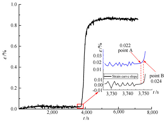
Figure 12.
The generalized strain evolution curve of the frost-heave crack propagation of specimen A1.
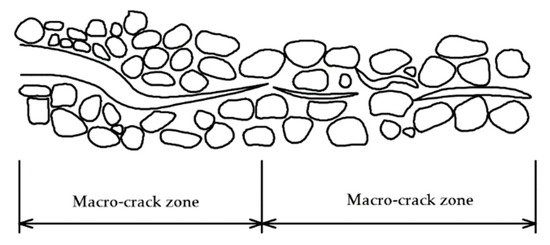
Figure 13.
Frost-heave propagation of cracks.
The crack-propagation processes of other specimens were analyzed using the same method that was used for specimen A1. The parameters of micro-crack initiation strain and unstable propagation strain for each specimen are shown in Table 3. From the table, it can be seen that the crack initiation strain and unstable crack propagation strain are little affected by external temperature, crack width, or the initial moisture content of the crack. The propagation strain is mainly related to material parameters. The average values of micro-crack initiation strain and unstable propagation strain were 224 με and 243 με, respectively.

Table 3.
Crack initiation and unstable propagation strain.
From Table 3, it can be seen that there are differences in the crack initiation strain and unstable strain of different specimens. The reason for this is that there were differences in the processes of pouring and curing, which affects the strength of concrete specimens. However, since there was little difference between the ratio of the crack initiation strain to the unstable strain among the specimens, it can be concluded that the test data can be used to effectively analyze the whole process of crack propagation. It is worth noting that, since the crack-tip strain measured by the traditional strain gauge is the average of the strain gauge’s target range, and the concrete crack strain measured here is similar to the crack-tip point strain, it is slightly larger than that obtained by traditional strain gauge tests.
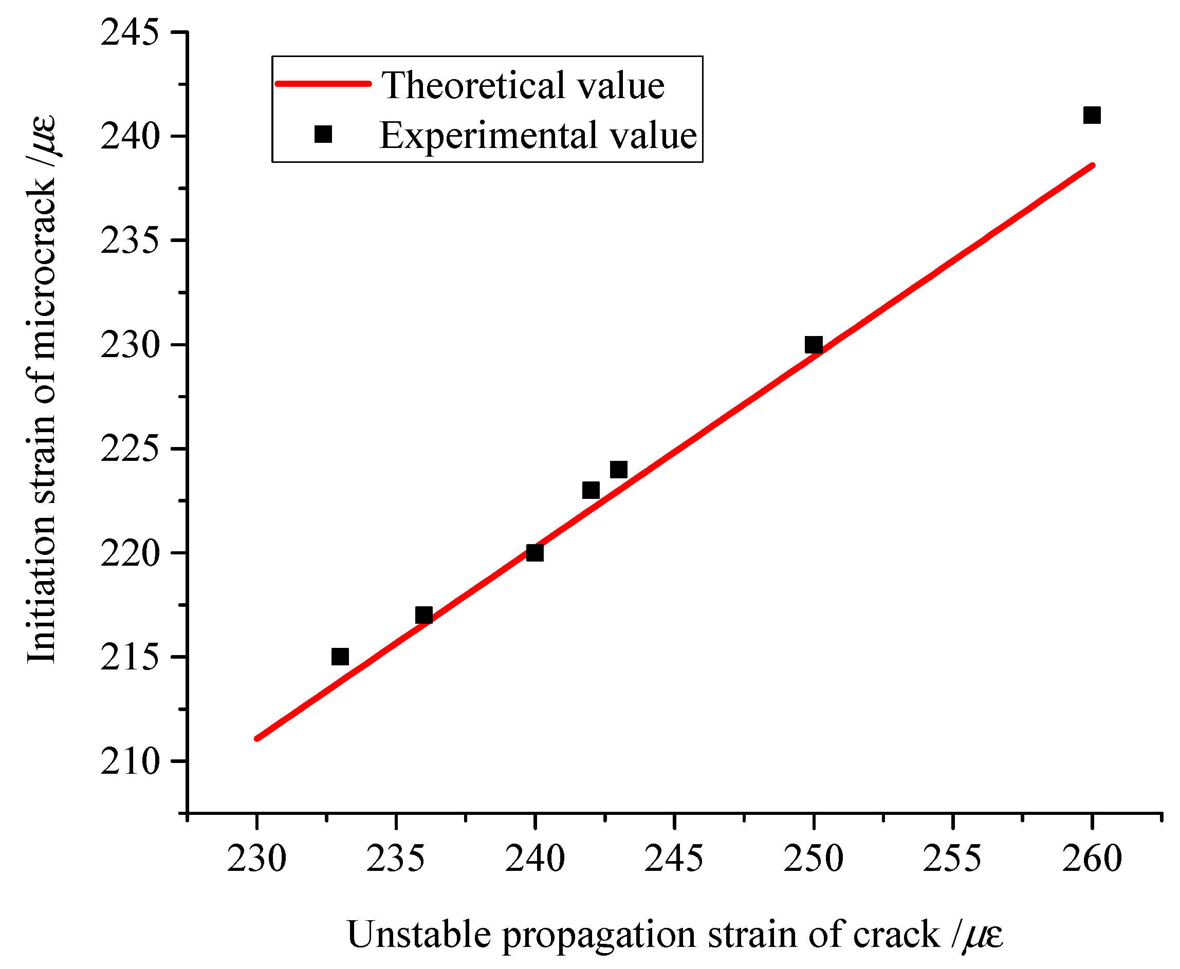
Reference [48] shows that, for concrete with 0.062 ≤ α ≤ 0.172, C60 concrete has an α of 0.074 and a Poisson’s ratio of 0.25. By substituting Equation (19), the relationship between crack-initiation strain and instability strain can be obtained, as shown in Figure 11. The theoretical and experimental values of crack initiation strain for each specimen are also depicted in Figure 11.
From Figure 14, it can be seen that the theoretical values of crack initiation strain are basically consistent with the experimental results obtained in this study. Therefore, the double-strain model proposed in this paper can be used to evaluate the whole process of crack propagation, which avoids the need to determine the stress intensity factor at the crack tip and the fracture toughness of materials under a complex frost-heave force.
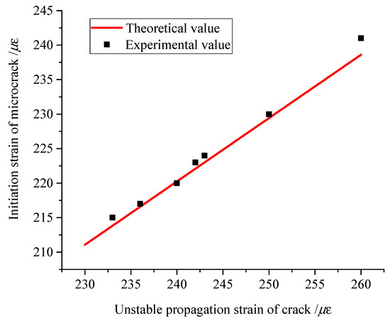
Figure 14.
The relationship between crack initiation strain and unstable propagation strain.
3.3. Analysis of Factors Affecting Frost-Heave Crack Propagation
As can be seen from Figure 11, the crack width, exterior temperature, and initial moisture content have different effects on the final propagation state of cracks. Therefore, it is necessary to further study the influence of different factors on the propagation state of cracks by means of the double-strain model proposed in this paper.
3.3.1. Influence of Crack Width
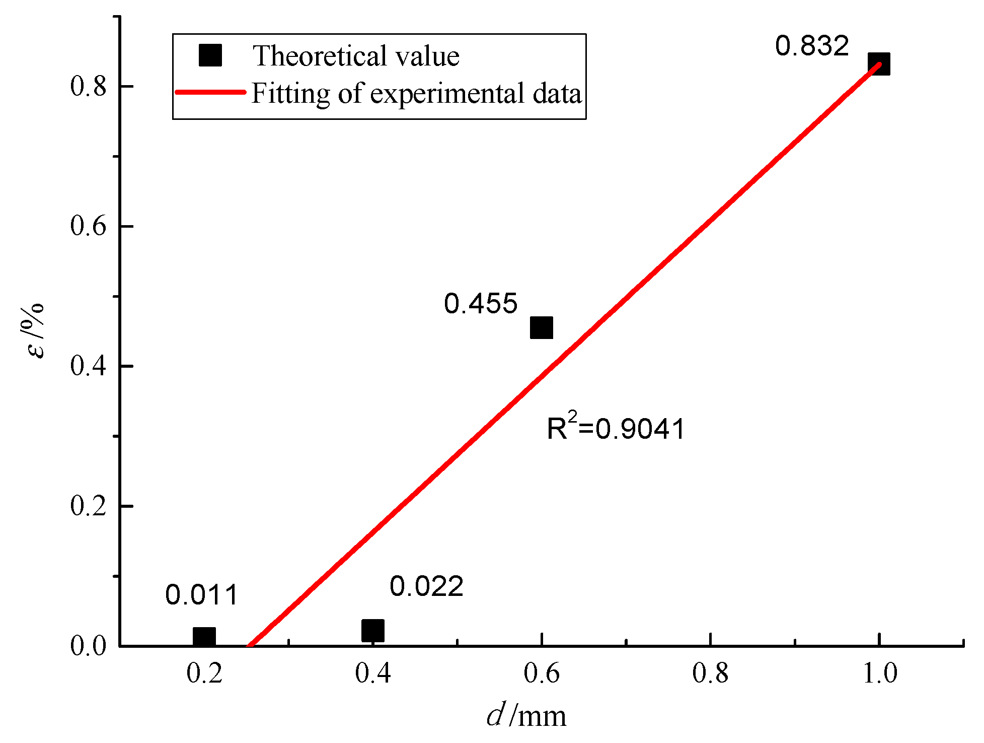
The average value of the strain curve after peak stabilization should be considered as the maximum generalized strain at the crack tip, as shown in Figure 11a. The relationship between the maximum generalized strain and the crack width of concrete specimens is given in Figure 15.
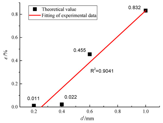
Figure 15.
The relationship between the maximum generalized strain at the crack tip and crack width (d).
A linear model fit was used in this study, as it could better fit the experimental data. The expression between the generalized strain and crack width is presented as follows:
Propagation is prone to occur can be obtained, i.e., d > 0.27 mm. Therefore, corresponding maintenance measures should be undertaken for cracks with a width larger than 0.27 mm to avoid further crack propagation under frost-heave force and thus ensure the durability of slab-tracks.
3.3.2. Influence of External Temperature
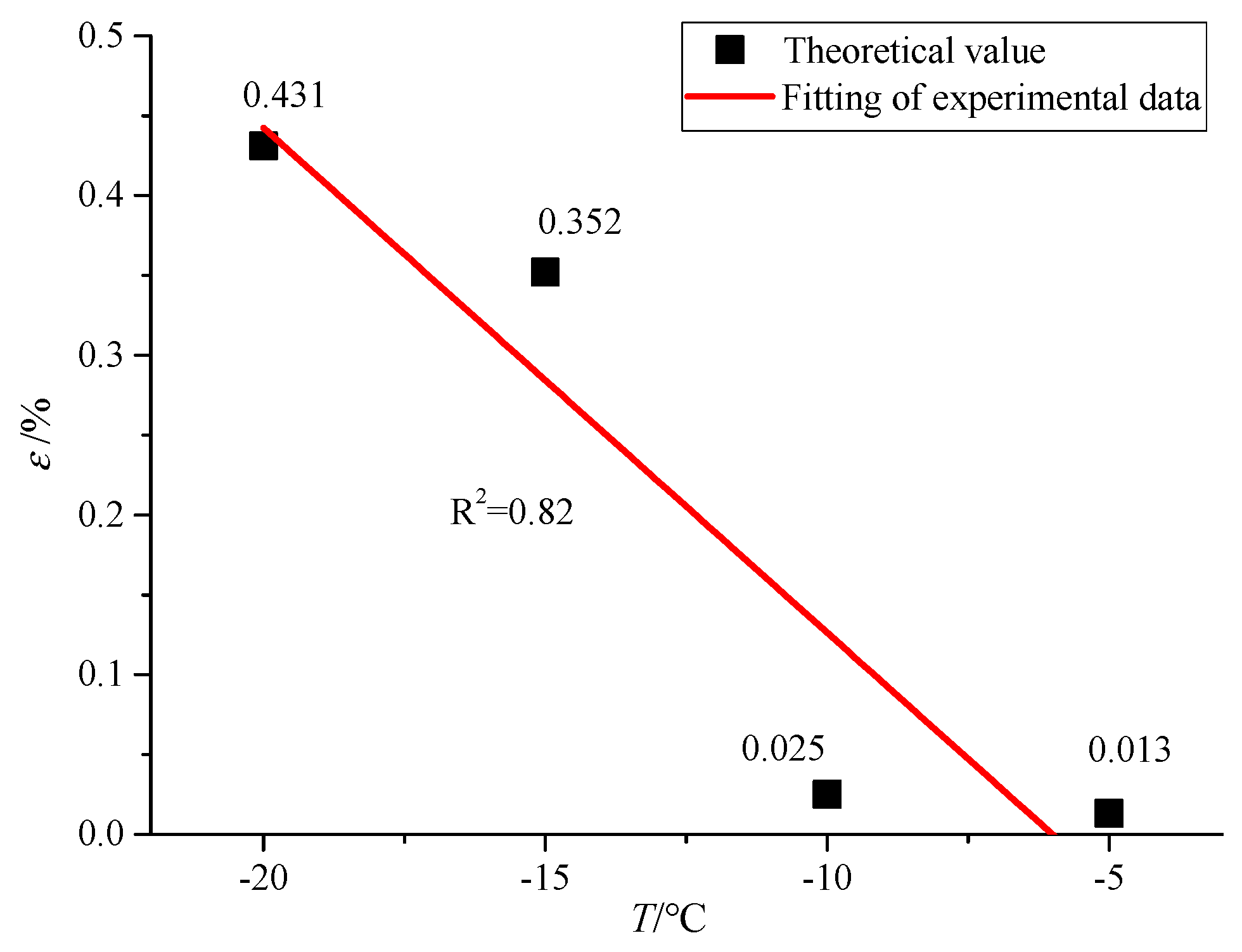
The average value of the strain curve after peak stabilization should be regarded as the maximum generalized strain at the crack tip, as shown in Figure 11b. The relationship between the maximum generalized strain and the exterior temperature is illustrated in Figure 16. Linear model fitting was employed in this study, as it could better fit the experimental data. The expression between the generalized strain and the external temperature was obtained as follows:
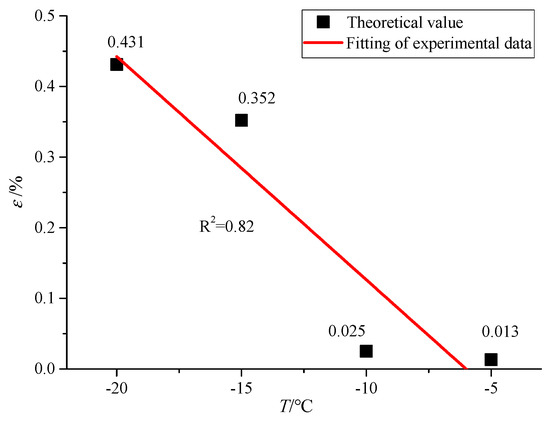
Figure 16.
The relationship between the maximum generalized strain at the crack tip and the external temperature (T).
By introducing εini into Equation (21), the outdoor temperature range of the crack with which frost-heave propagation is prone to occur can be obtained, i.e., T < −6.6 °C. There are a large number of cold regions around the world. For example, cold regions make up 53.5% of the total area of China. Consequently, maintenance measures should be taken to prevent crack damage in areas where the temperature drops below −6.6 °C. This provides a suggestion for the prevention and maintenance of frost-heave cracking damage to slab-tracks in different areas.
3.3.3. Influence of Initial Crack Moisture Content
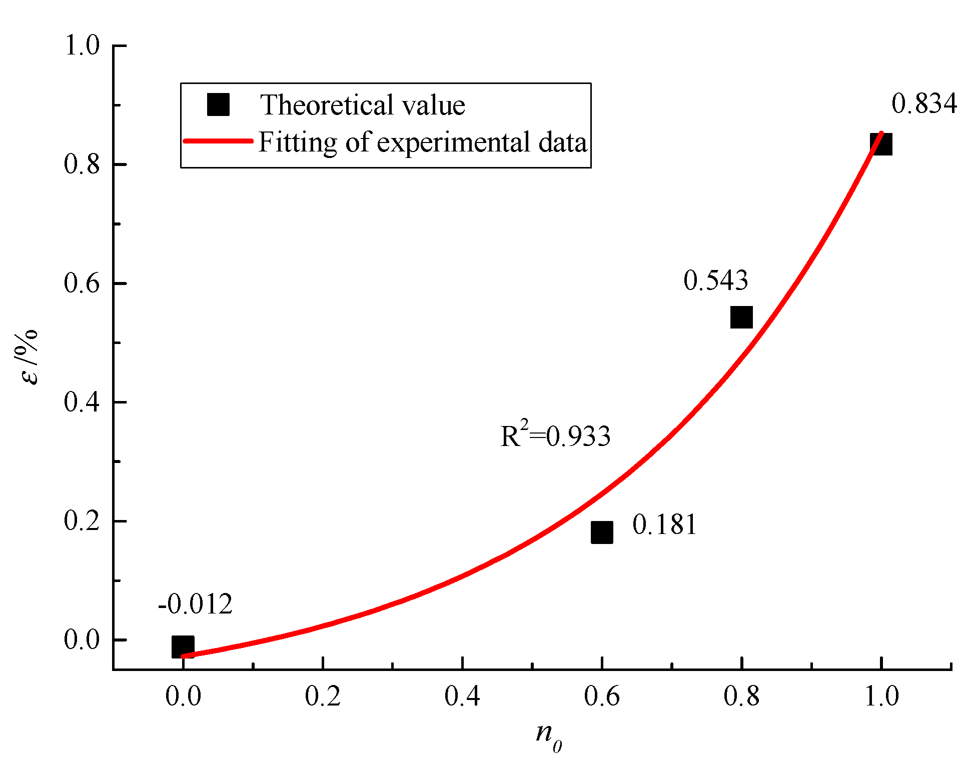
The average value of the strain curve after peak stabilization should be regarded as the maximum generalized strain at the crack tip, as shown in Figure 11c. The relationship between the maximum generalized strain and the initial crack moisture content of the concrete specimens is shown in Figure 17. Exponential model fitting was employed in this study, as it could better fit the experimental data. The expression between generalized strain and crack initial moisture content (n0) is obtained as follows:
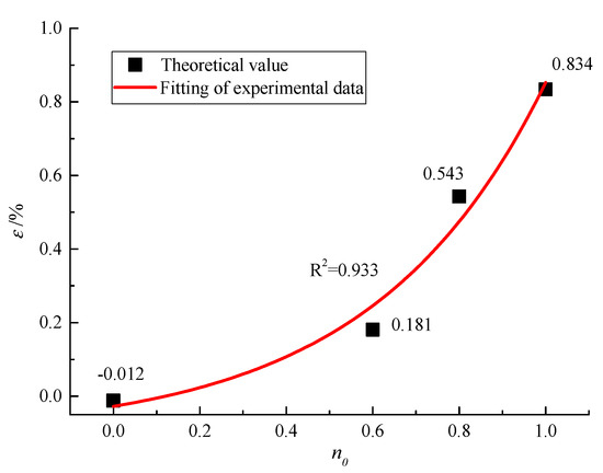
Figure 17.
The relationship between the maximum generalized strain at the crack tip and the initial moisture content of the crack (n0).
By inserting εini into Equation (22), it was concluded that when the moisture content of the crack is larger than 20%, cracking is initiated. The frost-heave crack propagation is highly sensitive to the moisture content in the cracks. Crack-sealing measures are usually adopted to prevent fracture damage to slab-tracks. Therefore, before such crack sealing, the crack moisture content should be strictly controlled to avoid frost-heave damage caused by residual water in slab-track cracks.
3.3.4. Suggestions for Maintenance Measures
Repair methods for concrete cracks can be divided into three categories: the surface closure method, the pressure-free grouting method, and the low-pressure grouting method. Combined with the determination criteria of China’s slab-track damage grade and the results of this study, maintenance recommendations are given as shown in Table 4.

Table 4.
Slab-track bed damage grade and maintenance recommendations.
4. Conclusions
Based on DIC and AE technology, in this study, the process of frost-heave crack propagation in concrete specimens was studied, respectively. An evolution law of generalized strain (ε) and AE events location on the surface of the specimens during frost-heave crack propagation is revealed. Using experiment-based analysis, a double-strain criterion for frost-heave crack propagation and factors affecting frost-heave crack propagation were investigated. The main conclusions can be summarized as follows:
(1) Based on DIC and AE technology, in this study, the process of frost-heave crack propagation in concrete specimens was studied respectively. This verified the correctness of using the surface strain at the crack tip to study the frost-heave crack propagation process. Additionally, methods for determining double-strain fracture parameters (micro-crack initiation strain and unstable strain) using the DIC technique were suggested.
(2) By studying the frost-heave crack propagation process, it was found that the frost-heave crack propagation was caused by an ice plug which formed at the crack opening. The process of crack propagation was divided into five different stages. For more detail sees Section 3.1.
(3) It was found that a computer-based DIC technique which captures continuous full-field strains can be used to adequately investigate the crack-initiation and crack-propagation processes of concrete specimens under frost-heave. The average values of micro-crack initiation strain and unstable propagation strain were found to be 224 με and 243 με, respectively. Moreover, frost-heave crack propagation was found to belong to mode I crack.
(4) The double-strain model set out in this paper can be used to evaluate the whole process of crack propagation, which avoids the need to determine the stress intensity factor at the crack tip and the fracture toughness of materials under complex frost-heave force.
(5) When the crack width is larger than 0.27 mm and the external temperature is lower than −6.6 °C, cracks propagate easily under the frost-heave force. Therefore, it is suggested that corresponding maintenance measures should be taken for cracks with a width larger than 0.27 mm to avoid the further propagation of cracks under frost-heave force and ensure the durability of slab-tracks.
(6) Frost-heave crack propagation is highly sensitive to the moisture content in the cracks. Crack-sealing measures are usually adopted to prevent fracture damage to slab-tracks. Therefore, before crack sealing in slab-tracks, the crack moisture content should be strictly controlled to avoid frost-heave damage to slab-track caused by residual water in cracks.
Author Contributions
Data curation, X.C. and W.Z.; Funding acquisition, L.G., X.C. and Y.Z.; Investigation, W.Z. and Y.H.; Methodology, F.T.; Writing—original draft, F.T.; Writing—review and editing, L.G. and Y.Z.
Funding
The present work was supported by the Fundamental Research Funds for the Central Universities (2019JBZ002, 2019JBM080), the National Natural Science Foundation of China (No. 51578053, No.51908031, No.U1734206, No. 51827813), the Opening Foundation of National Laboratory (RCS2019ZZ006), and the Project of Science and Technology Research and Development Program of the China Railway Corporation (2017G010-A).
Acknowledgments
Thanks to Chen Jinjie and Wang Jianxi of Shijiazhuang Railway University for their valuable experience in experiment and theory.
Conflicts of Interest
The authors declare no conflict of interest.
References
- Gautier, P.E. Slab track: Review of existing systems and optimization potentials including very high speed. Constr. Build. Mater. 2015, 92, 9–15. [Google Scholar] [CrossRef]
- Wang, Z.J.; Shu, X.; Rutherford, T.; Huang, B.; Clarke, D. Effects of asphalt emulsion on properties of fresh cement emulsified asphalt mortar. Constr. Build. Mater. 2015, 75, 25–30. [Google Scholar] [CrossRef]
- Lin, Z.; Niu, F.; Li, X.; Li, A.; Liu, M.; Luo, J.; Shao, Z. Characteristics and controlling factors of frost heave in high-speed railway subgrade northwest China. Cold Reg. Sci. Technol. 2018, 153, 33–44. [Google Scholar] [CrossRef]
- Ministry of Railways of China. Maintenance Rules for Slab Track Lines of High-Speed Railway (Trial Implementation); TG/GW 115-2012; China Railway Press: Beijing, China, 2012. [Google Scholar]
- Gong, J.Q.; Zhang, W.J. The effects of pozzolanic powder on foam concrete pore structure and frost resistance. Constr. Build. Mater. 2019, 208, 135–143. [Google Scholar] [CrossRef]
- Qin, Z.P.; Lai, Y.M.; Tian, Y.; Yu, F. Frost-heaving mechanical model for concrete face slabs of earthen dams in cold regions. Cold Reg. Sci. Technol. 2019, 161, 91–98. [Google Scholar] [CrossRef]
- Hu, Z.; Hao, D.; Lai, J.; Wang, H.; Wang, X.; He, S. The durability of shotcrete in cold region tunnel: A review. Constr. Build. Mater. 2018, 185, 670–683. [Google Scholar] [CrossRef]
- Zeng, Z.P.; Wang, J.D. Experimental study on evolution of mechanical properties of CRTS III Ballastless slab track under fatigue load. Constr. Build. Mater. 2019, 210, 639–649. [Google Scholar]
- Chen, L.; Chen, J.J.; Wang, J.X. Calculation of reasonable tension value for longitudinal connecting reinforcement of CRTSII Ballastless slab track. Appl. Sci. 2018, 8, 2139. [Google Scholar] [CrossRef]
- Ren, J.; Li, X.; Yang, R.; Wang, P.; Xie, P. Criteria for repairing damages of CA mortar for prefabricated framework-type slab track. Constr. Build. Mater. 2016, 110, 300–311. [Google Scholar] [CrossRef]
- Liu, L.; Shen, D.; Chen, H.; Sun, W.; Qian, Z.; Zhao, H.; Jiang, J. Analysis of damage development in cement paste due to ice nucleation at different temperatures. Cem. Concr. Compos. 2014, 53, 1–9. [Google Scholar] [CrossRef]
- Liu, Q.S.; Huang, S.B.; Kang, Y.S.; Liu, J.P. Preliminary study of frost heaving pressure and its influence on crack and deterioration mechanisms of rock mass. Rock Soil Mech. 2016, 37, 1530–1542. [Google Scholar]
- Hu, L.D.; Wu, Y.H.; Li, X.Y. A field study on the freezing characteristics of freeze-sealing pipe roof used in ultra-shallow buried tunnel. Appl. Sci. 2019, 9, 1532. [Google Scholar] [CrossRef]
- Tan, X.J.; Chen, W.Z.; Liu, H.Y.; Wang, L.Y.; Ma, W.; Chan, A.H.C. A unified model for frost heave pressure in the rock with a penny-shaped fracture during freezing. Cold Reg. Sci. Technol. 2018, 153, 1–9. [Google Scholar] [CrossRef]
- Huang, S.B.; Liu, Q.S.; Liu, Y.Z.; Kang, Y.S.; Cheng, A.P.; Ye, Z.Y. Frost heaving and frost cracking of elliptical cavities (fractures) in low permeability rock. Eng. Geol. 2018, 234, 1–10. [Google Scholar] [CrossRef]
- Hassanzadeh, M.; Fagerlund, G. Residual strength of the frost-damaged reinforced concrete beams. In III European Conference on Computational Mechanics; Springer: Berlin, Germany, 2006; p. 366. [Google Scholar]
- Zandi Hanjari, K.; Kettil, P.; Lundgren, K. Modelling the structural behaviour of frost-damaged reinforced concrete structures. Struct. Infrastruct. Eng. 2013, 9, 416–431. [Google Scholar] [CrossRef]
- Huang, S.B.; Liu, Q.S.; Cheng, A.P.; Liu, Y.Z. Preliminary experimental study of frost heaving pressure in crack and frost heaving propagation in rock mass under low temperature. Rock Soil Mech. 2018, 39, 1–8. [Google Scholar]
- Cai, C.X.; Zhi, T.L. Transversely isotropic frost heave of saturated rock under unidirectional freezing condition and induced frost heaving force in cold region tunnels. Cold Reg. Sci. Technol. 2018, 152, 48–58. [Google Scholar]
- Roubin, E.; Andò, E.; Roux, S. The colours of concrete as seen by X-rays and neutrons. Cem. Concr. Compos. 2019, 104, 1–10. [Google Scholar] [CrossRef]
- Tian, W.; Han, N. Analysis on meso-damage processes in concrete by X-ray computed tomographic scanning techniques based on divisional zones. Measurement 2019, 140, 382–387. [Google Scholar] [CrossRef]
- Promentilla, M.A.B.; Cortez, S.M.; Papel, R.; Tablada, B.; Sugiyama, T. Evaluation of microstructure and transport properties of deteriorated cementitious materials from their X-ray computed tomography (CT) images. Materials 2016, 9, 388. [Google Scholar] [CrossRef]
- Ren, W.; Yang, Z.; Sharma, R.; Zhang, C.H.; Withers, P.J. Two-dimensional X-ray CT image based meso-scale fracture modelling of concrete. Eng. Fract. Mech. 2015, 133, 24–39. [Google Scholar] [CrossRef]
- Schock, J.; Liebl, S.; Achterhold, K.; Pfeiffer, F. Obtaining the spacing factor of microporous concrete using high-resolution Dual Energy X-ray Micro CT. Cem. Concr. Res. 2016, 89, 200–205. [Google Scholar] [CrossRef]
- Hoegh, K.; Khazanovich, L.; Yu, H.T. Ultrasonic tomography for evaluation of concrete pavements. Transp. Res. Rec. J. Transp. Res. Board 2011, 2232, 85–94. [Google Scholar] [CrossRef]
- Perlin, L.P.; Pinto, R.C.D. Use of network theory to improve the ultrasonic tomography in concrete. Ultrasonics 2019, 96, 185–195. [Google Scholar] [CrossRef]
- Sause, M.G.R. In-Situ Monitoring of Fiber-Reinforced Composites; Springer: Berlin, Germany, 2016; pp. 110–140. [Google Scholar]
- Grosse, C.U.; Ohtsu, M. Acoustic Emission Testing; Springer: Berlin, Germany, 2008; pp. 3–5. [Google Scholar]
- Sagasta, F.; Zitto, M.E. Acoustic emission energy b-value for local damage evaluation in reinforced concrete structures subjected to seismic loadings. Mech. Syst. Signal Process. 2018, 102, 262–277. [Google Scholar] [CrossRef]
- Benavent-Climent, A.; Gallego, A. An acoustic emission energy index for damage evaluation of reinforced concrete slabs under seismic loads. Struct. Health Monit. 2012, 11, 69–81. [Google Scholar] [CrossRef]
- Sagasta, F.; Benavent-Climent, A.; Roldán, A.; Gallego, A. Correlation of plastic strain energy and acoustic emission energy in reinforced concrete structures. Appl. Sci. 2016, 6, 84. [Google Scholar] [CrossRef]
- Castillo, E.D.; Allen, T.; Henry, R.; Griffith, M.; Ingham, J. Digital image correlation (DIC) for measurement of strains and displacements in coarse, low volume-fraction FRP composites used in civil infrastructure. Compos. Struct. 2019, 212, 43–57. [Google Scholar] [CrossRef]
- Dzaye, E.D.; Tsangouri, E.; Spiessens, K.; De Schutter, G.; Aggelis, D.G. Digital image correlation (DIC) on fresh cement mortar to quantify settlement and shrinkage. Arch. Civ. Mech. Eng. 2019, 19, 205–214. [Google Scholar] [CrossRef]
- Tetsuya, I.; Kolneath, P.; Tanaka, Y.; Kashimura, K.; Iwaki, I. Numerical simulation of early age cracking of reinforced concrete bridge decks with a full-3D multiscale and multi-chemo-physical integrated analysis. Appl. Sci. 2018, 8, 394. [Google Scholar]
- Zhu, S.Y.; Wang, M.Z.; Zhai, W.; Cai, C.; Zhao, C.; Zeng, D.; Zhang, J. Mechanical property and damage evolution of concrete interface of slab track in high-speed railway: Experiment and simulation. Constr. Build. Mater. 2018, 187, 460–473. [Google Scholar] [CrossRef]
- The National Railway Administration of China. Code for Design of High-Speed Railways; TB 10621-2014; China Railway Press: Beijing, China, 2014. [Google Scholar]
- Ministry of Construction of China. Standard for Test Methods of Mechanical Properties of Ordinary Concrete State; GB/T50081-2002; China Architecture & Building Press: Beijing, China, 2002. [Google Scholar]
- Wang, L.M.; HAN, W.W.; Chen, T.; Wang, H.Y.; Han, D.P. On the linking of microcrack damage and macro fracture of quasi-brittle materials. Chin. J. Solid Mech. 2015, 36, 20–25. [Google Scholar]
- Bhowmik, S.; Ray, S. An experimental approach for characterization of fracture process zone in concrete. Eng. Fract. Mech. 2019, 211, 401–419. [Google Scholar] [CrossRef]
- Carpinteri, A.; Massabó, R. Reversal in failure scaling transition of fibrous composites. J. Eng. Mech. ASCE 1997, 123, 107–114. [Google Scholar] [CrossRef]
- Ooi, E.T.; Yang, Z.J. Modelling crack propagation in reinforced concrete using a hybrid finite element–scaled boundary finite element method. Eng. Fract. Mech. 2011, 78, 252–263. [Google Scholar] [CrossRef]
- Wu, Z.M.; Dong, W.; Liu, K.; Yang, S.T. Mode I crack propagation criterion of concrete and numerical simulation on complete process of cracking. J. Hydraul. Eng. 2007, 38, 1453–1459. [Google Scholar]
- Dong, W.; Wu, Z.; Zhou, X. Calculating crack extension resistance of concrete based on a new crack propagation criterion. Constr. Build. Mater. 2013, 38, 879–889. [Google Scholar] [CrossRef]
- Zhang, X.M. Fracture Mechanics, Version 1; Tsinghua University Press: Beijing, China, 2012; pp. 12–27. [Google Scholar]
- Yu, M.H. Linear and nonlinear unified strength theory. Chin. J. Rock Mech. Eng. 2007, 26, 662–669. [Google Scholar]
- Yu, M.H.; Zan, Y.W.; Xu, S.Q. Rock Strength Theory and Its Application, Version 1; Science Press: Beijing, China, 2017; pp. 145–163. [Google Scholar]
- Malumela, G.; Alexander, M.; Moyo, P. Lateral deformation of RC beams under simultaneous load and steel corrosion. Constr. Build. Mater. 2010, 24, 17–24. [Google Scholar] [CrossRef]
- Ministry of Housing and Urban-Rural Construction of the People’s Republic of China. Code for Design of Standard Concrete Structures; GB/50010-2010; China Architecture & Building Press: Beijing, China, 2010. [Google Scholar]
© 2019 by the authors. Licensee MDPI, Basel, Switzerland. This article is an open access article distributed under the terms and conditions of the Creative Commons Attribution (CC BY) license (http://creativecommons.org/licenses/by/4.0/).

