Article

Research of Modal Analysis for Impeller of Reactor Coolant Pump

1
State Key Laboratory of Fluid Power & Mechatronic Systems, Zhejiang University, Hangzhou 310027, China
2
School of Engineering, Zhejiang University City College, Hangzhou 310015, China
3
College of Energy Engineering, Zhejiang University, Hangzhou 310027, China
*
Author to whom correspondence should be addressed.
Appl. Sci. 2019, 9(21), 4551; https://doi.org/10.3390/app9214551
Submission received: 26 September 2019 / Revised: 18 October 2019 / Accepted: 22 October 2019 / Published: 26 October 2019
(This article belongs to the Section Mechanical Engineering)

Abstract

:

Featured Application

This work has applications to the fields of impeller design and structural analysis. It can be applied to study the dynamic characteristics of the impeller and prevent hydraulic resonance.

Abstract

This paper studies the influence of added mass, centrifugal force and hydraulic load on natural frequencies of a Reactor Coolant Pump (RCP) impeller. A series of comparative studies under different conditions were carried out on a modal test bench and a simulation platform. Modal analysis of a full-scale RCP impeller was conducted by simulation, and an improved design of impeller was proposed to prevent hydraulic resonance. These results indicated that hydraulic load increases natural frequencies of the impeller. While the centrifugal force slightly reduces them, but it is negligible. Because the distribution of hydraulic load has an effect to natural frequencies, a solution of cutting inlet edges of blades can be used to increase the natural frequency that may cause hydraulic resonance. In summary, our research shows that both added mass and hydraulic load have a significant influence on natural frequencies of the RCP impeller, and redistributing the hydraulic load can alter natural frequencies of the impeller.

1. Introduction

The reactor coolant pump (RCP) drives cooling water circulation in the nuclear power plant [1], which brings the heat of the nuclear reactor to the steam generator, thereby producing steam to generate electricity. The RCP impeller rotates at high speed in a high-temperature, high-pressure and strong-radiation environment [2,3]. To ensure the long-term operation of the nuclear power plant, hydraulic resonance should be avoided [4]. However, it is challenging to accurately calculate natural frequencies of the rotating RCP impeller in high-temperature liquid [5]. Therefore, it is necessary to figure out the impact of different factors and propose a modal analysis method for the underwater rotating impeller.
The natural frequencies of solids in liquid are different from those in the air [6]. Due to added mass, wet modal natural frequencies of solids are lower than dry modal natural frequencies [7] (The state of a solid in the air is called dry modal, and the state of a solid in water is called wet modal). Besides, rotating centrifugal force and pre-stress also have an influence on natural frequencies. Li W. [8] performed modal tests on rotors at different speeds and discovered that centrifugal force increases natural frequencies of rotors. Zhang Y.F. et al. [9] carried out dynamic tests on five pre-stressed concrete beams, and found that natural frequencies of those beams increase in step with pre-stress force. In summary, added mass, centrifugal force and pre-stress all can affect natural frequencies of the structure.
Some researchers have studied the vibration modal of scale RCP impeller. For example, Zhang Y.T. [10] measured natural frequencies of a wet modal static impeller and found the impact of boundary conditions. Xu. S et al. [11] analyzed the damping ratio of the underwater static impeller and calculated the dynamic magnification coefficient. However, they only took the influence of added mass into account, while the rotating RCP impeller under operation condition can also be subject to centrifugal force and hydraulic load. Therefore, their studies towards the modal analysis of the RCP impeller are insufficient. The influence of added mass, centrifugal force and hydraulic load on natural frequencies of the rotating impeller should be counted.
This study analyzed the modal of a scale RCP impeller by theory, and then compared natural vibration modes of the impeller under different conditions by experiment and simulation. An underwater vibration test system was innovatively designed in this research. Through it, the vibrant signals of both static and rotating blades can be brought out, so that natural frequencies under both static and rotating conditions can be measured. Then a simulation was performed synchronously with the test bench to collect more data. According to the comparison among modal data in different environments, it is found that both added mass and hydraulic load have a great influence on natural frequencies of the RCP impeller, but the impact of centrifugal force on them can be ignored. Finally, hydraulic resonance analysis of an RCP impeller was carried out, and a solution of cutting inlet edges of blades was implemented to avoid resonance of the impeller.

2. Modal Analysis of the Impeller

In order to clarify the specific influences of these three factors on natural frequencies, a series of comparative studies were conducted. On the bench test, the natural frequencies of the impeller under three conditions (static in the air, static in water and rotating in water) were tested. Then on the simulation platform, the influence of rotation on natural frequencies was studied.

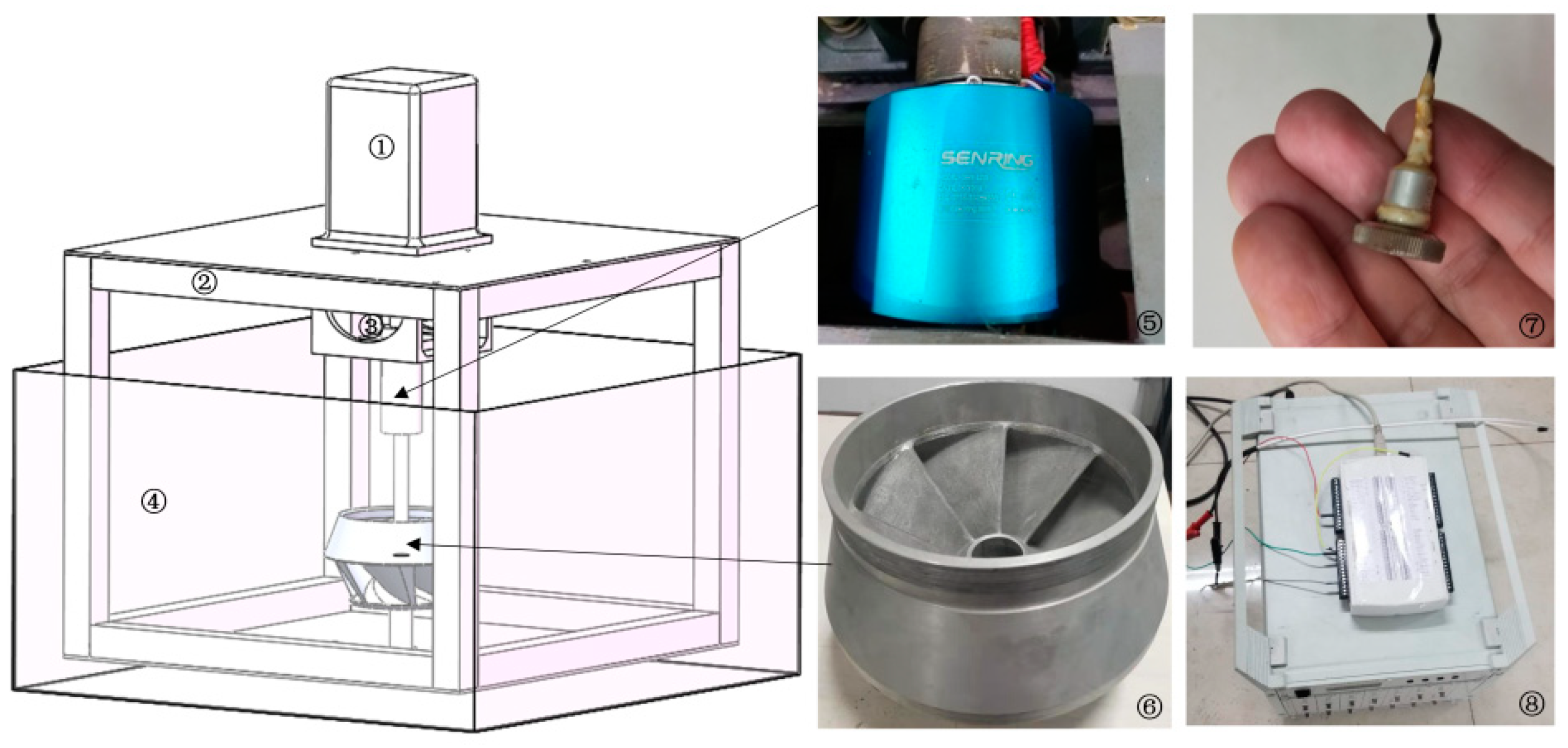
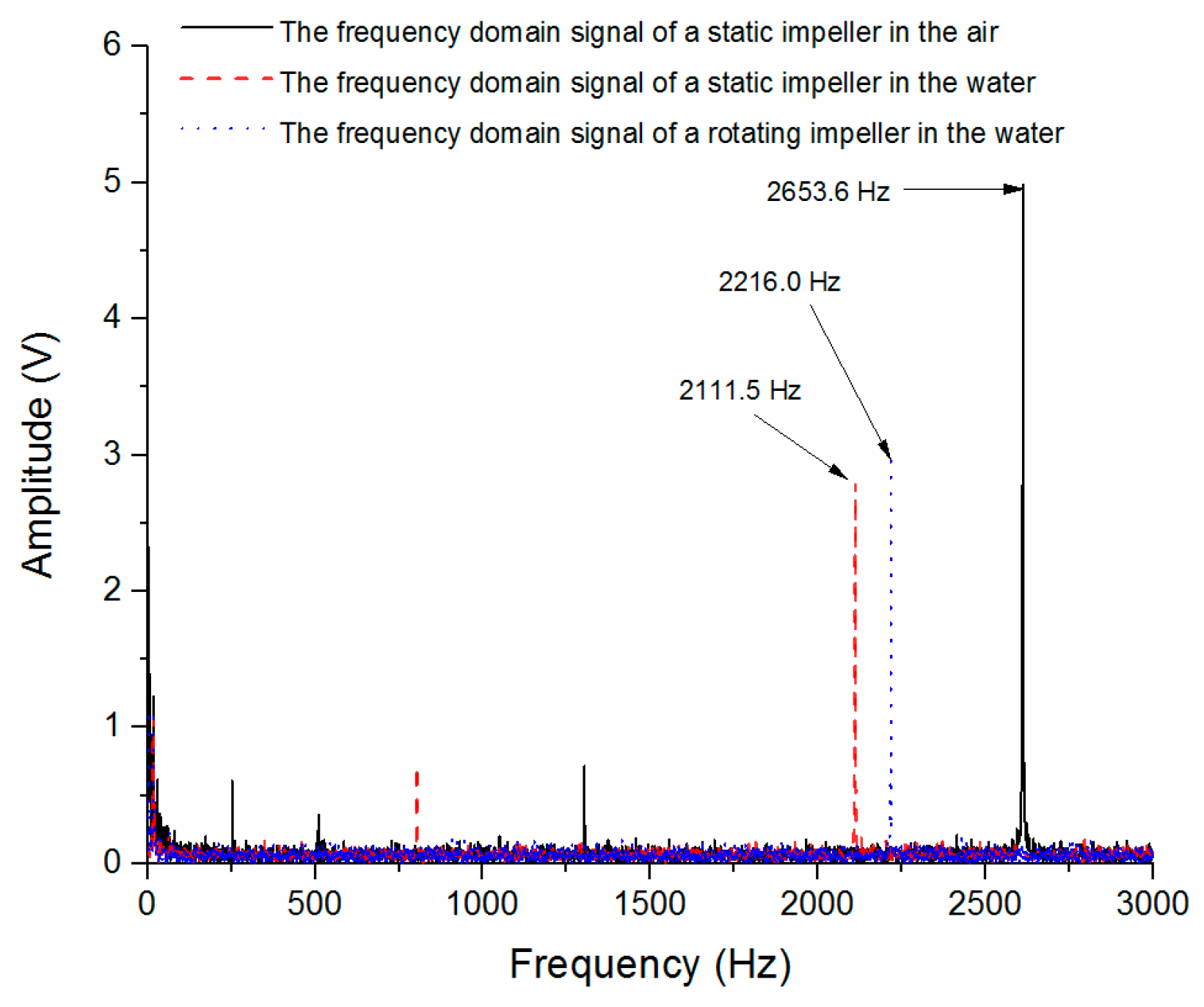
2.1. Modal Experiment

Due to limitations of the test environment, a 0.1 scale RCP impeller (maximum diameter of 92 mm and height of 53 mm) was taken as the research object. In order to measure natural frequencies of the impeller in water, it is necessary to transmit rotating vibration signals to collectors. This study installed the motor upside down, and immersed the shafting in the tank. The test schematic diagram is shown in Figure 1. Upper and lower bearings with end caps are used to ensure stable rotation of the spindle. The motor is inverted above the frame. A rigid coupling connects the upper end of the spindle to the motor output shaft. The signal testing equipment mainly includes waterproof, magnetic, piezoelectric accelerometers [12], charge amplifiers, NI (National Instruments) Data Acquisition Card, slip rings and a computer for monitoring data. This test platform is being applied for a Chinese patent. In addition to measuring natural frequencies, it can be used to test the blade vibration when the interaction occurs between rotor and stator.
In our test, the transient excitation method [13] was applied to the static impeller in the air (also in water). The excitation point was arranged at the inlet edge of the impeller hub. Furthermore, the spectral analysis method [14] was applied to the rotating impeller in water. Magnetic piezoelectric acceleration sensors were attached to the surfaces of blades [15], the slip ring exported the electric vibration signal on the surface of the impeller to the charge amplifier, and then the NI Data Acquisition Card read vibration signals. It should be noted that a vortex generated by a high speed will make the impeller incompletely immersed in water, and the slip ring also has a limit on the rotational speed, so the experimental rotational speed is set to 100 r/min.
On this bench test, natural frequencies of the static impeller in the air (Condition A), the static impeller in water (Condition B) and the rotating impeller in water (Condition C) were measured. By Fast Fourier Transform Algorithm (FFT) analysis [16] and filter process (filtering shaft frequency and its multipliers), spectrograms of measured signals under these three conditions are shown in Figure 2. Natural frequencies of the impeller are 2653.6 Hz, 2111.5 Hz and 2216.0 Hz, respectively.

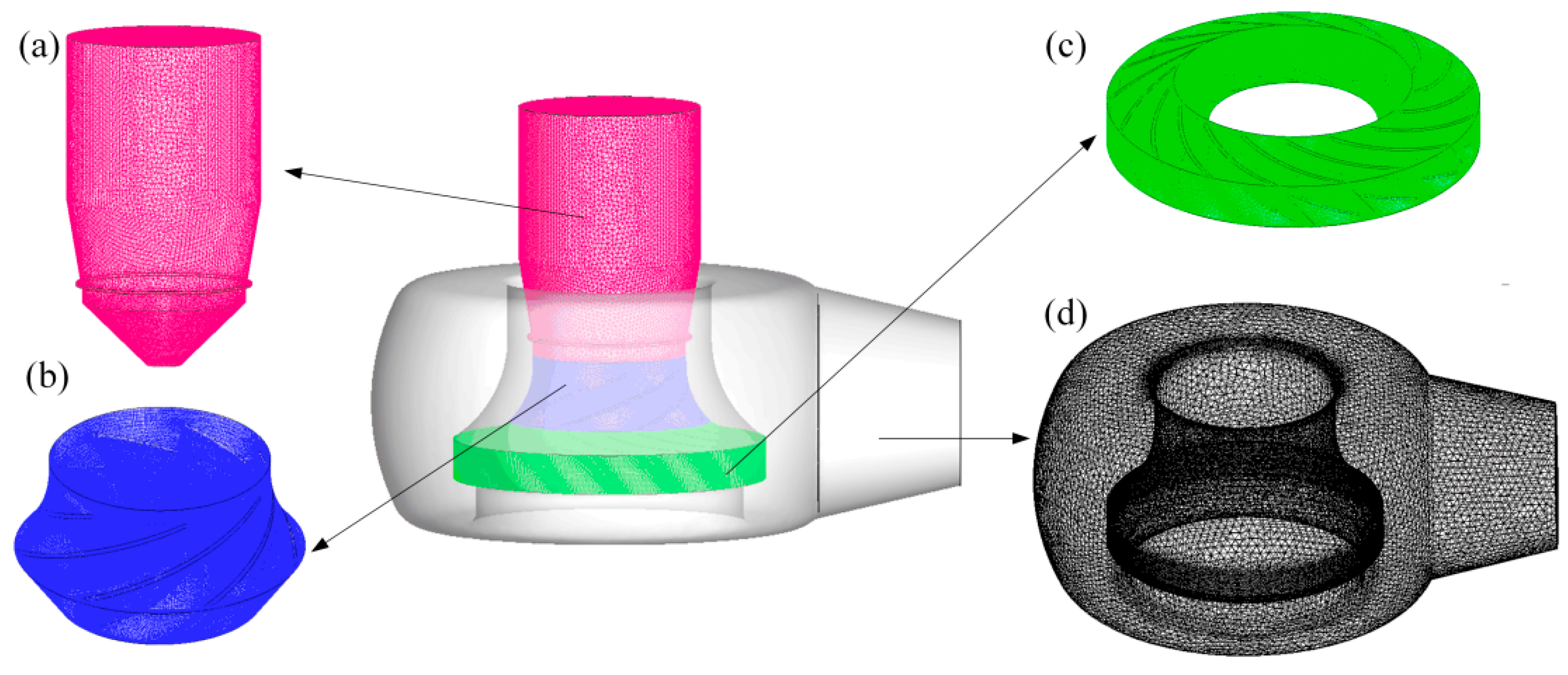
2.2. Modal Simulation

Due to the speed limitation of the slip ring mentioned in the above section, it is impossible to test a high-speed rotating impeller on our test bench. Therefore, the modal analysis of the rotating impeller in the air (Condition D, the rotational speed is 1800 r/min, which is the rated rotational speed of an RCP [17]) was carried out on a simulation platform. In order to ensure the accuracy of simulation, models under the other three conditions were also simulated. Modal simulation schemes for the impeller under Condition A, B and D are similar to those of researches mentioned in the introduction. Due to space limitation, this section only introduces the simulation of the impeller under Condition D.
Since the rotating impeller in water is subject to hydraulic load, before performing modal analysis, it is necessary to calculate pressure distribution on the surface of the impeller by flow simulation. The flow field state of the impeller in the tank is similar to that of a blender [18]. Fluid domain around the impeller is artificially divided into three parts: Internal rotating water, external still water and upper air. The flow simulation adopts the VOF (volume-of-fluid) two-phase flow model. The upper surface of the static water is set to free surface. In the water part, k-epsilon Reynolds average stress turbulence model is used for calculation, and the mixed-plane function is used for data transmission at the rotor-stator interface.
After flow simulation, pressure distribution on the impeller boundaries was extracted to solid boundaries of the modal simulation model. The model contains the impeller solid and external water. Fluid-solid acoustic coupling method is adopted in the modal simulation. Axial position constraint is set on the axial surface of the impeller. The upper surface of external water is set to a free surface. Parameters of the impeller solid are: A density of 7850 kg/m3, an elastic module of 210 GPa and a Poisson’s ratio of 0.3. Parameters of the water are: A density of 998.2 kg/m3 and a sound speed of 1500 m/s.

2.3. Result Analysis

Table 1 shows detailed simulation data of natural frequencies. Simulated first-order natural frequencies values of mode shape with one nodal diameter under Condition A, B and C are 2520.3 Hz, 1974.2 Hz, and 2045.5 Hz, respectively. Making a comparison between simulation results with test results, it can be concluded that errors of simulation results are 5.0%, 6.5%, and 7.7%, respectively. These errors may result from impeller machining internal defects, bearing damping and instability of the motor speed. Since these errors are small, it is highly reliable to analyze modal characteristics of a full-scale RCP impeller on the simulation platform.
By comparing natural frequencies of the impeller under Condition B with those under Condition A, it can be found that added mass leads to a decrease in natural frequencies, with about 20.0% for 0 nodal diameter mode, about 21.7% for one nodal diameter mode and about 14.0% for two nodal diameters mode. Compared with those of the static impeller in the air (Condition A), natural frequencies of the underwater rotating impeller (Condition C) reduce by about 14.7% for 0 nodal diameter mode, about 18.8% for one nodal diameter mode and about 3.7% for two nodal diameters mode. According to the simulation results of the impeller under Condition A and D, the changes of natural frequencies are so subtle that they can be ignored.

3. Resonance Analysis of the RCP Impeller

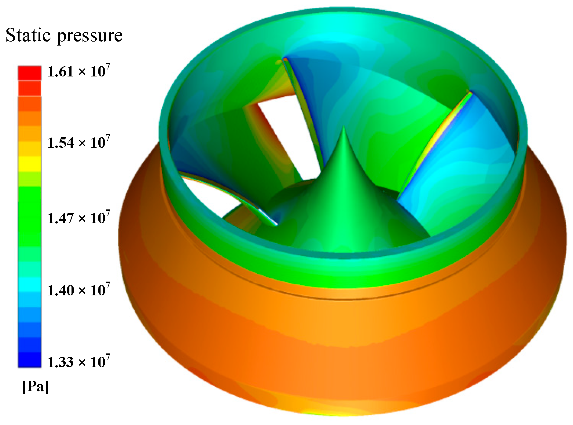
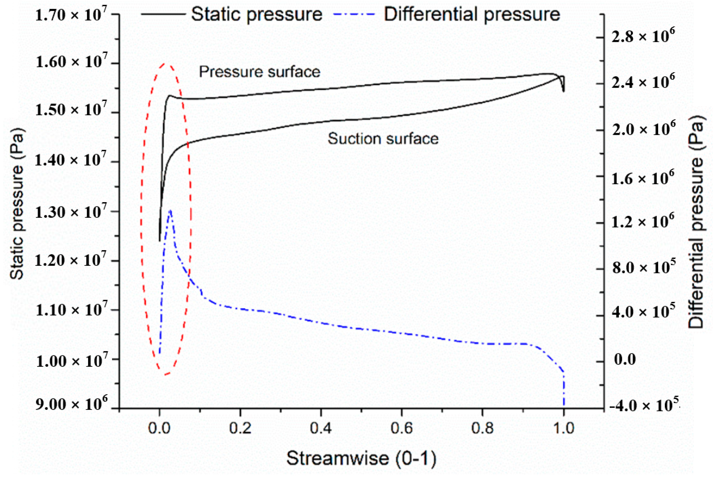
3.1. Flow Simulation of the RCP

In the researches above, the accuracy of the modal simulation scheme in water has been verified. The modal analysis of a full-scale RCP impeller was conducted on the simulation platform described in Section 2.2, which includes flow and modal simulation. The fluid model is artificially divided into four domains, namely, inlet fluid, impeller fluid, vane diffuser fluid and volute fluid. Software ANSYS-ICEM was used to construct the unstructured mesh of the model pump, which is shown in Figure 3. Grid cells near the wall were encrypted in order to ensure y + ≤1 in the wall-adjacent cells, and the maximum number of layers in the boundary layer is set to 20. The total number of mesh elements is 9,597,689. The preliminary flow simulation model of the RCP has been verified by grid independence verification [3] and performance test in our previous researches [19]. During normal operation, the temperature of the liquid in RCP is about 280 °C. Ignoring the influence of trace boric acid [20] and referring to the look-up table, it can be found that the physical property parameters of the liquid are a density of 750 kg/m3 and a viscosity of 9.6 × 10⁻⁵ kg/m·s. The RNG (Renormalization-group) k-epsilon turbulence model was used in the flow simulation. A second-order scheme of the spatial discretization was adopted by software FLUENT. The boundary conditions are as follows: Mass flow inlet is set at the inlet of pipe. Pressure outlet is set at the outlet of the volute. No slip walls are set at blade walls. The detailed flow simulation settings are shown in Table 2.
When the computation stopped, the steady-state static pressure on the impeller boundaries was recorded, which is shown in Figure 4. The static pressure on the outside of the hub is greater than that on the inside. Due to the seal of the wear ring, the static pressure on the outside is close to the outlet static pressure of the impeller. Figure 5 shows the static pressure on both sides of the blade. It indicates that the pressure difference between the two surfaces gradually decreases along the flow direction, which means that inlet edges of blades bear more load than outlet edges.
Applying the pressure distribution to boundary surfaces of the RCP impeller solid, natural vibration modes of the rotating impeller in high-temperature liquid (the speed of sound is 1020 m/s) were simulated. The modal results are shown in Figure 6; and it can be seen that the impeller vibrates in mode shapes with some uniformly distributed nodal diameters in the radial direction. Vibration modes with different radial nodal diameters have different motion directions, such as vibration modes with one nodal diameter coupled to bending motion of the axle [21].

3.2. Resonance Analysis of the Impeller

Guo et al. [22] held that a positive work by the exciting force is necessary for the resonance of a rotor system. Thus, when an impeller resonates, nodal diameters, blade numbers of the impeller and the vane diffuser should satisfy the following equation:
v 2 Z v = v 1 Z b ± m ,
with the number of impeller blades Zb, the number of vane diffuser blades Zv, any integer v1 and v2, and the number of nodal diameters m.
When the excitation frequency is close to the natural frequency of the system, the amplitude of the forced vibration will soar. Due to the rotor-stator interaction [23], the impeller is excited by periodic fluctuating pressure. Because the number of excitations per revolution is equal to the number of impeller blades, the frequency of the pressure on the impeller is the product of static blade number and the shaft frequency. All in all, if the natural frequency is the same as the frequency (or its multiples) of fluctuating pressure and the number of modal nodal diameters satisfies Equation (1), hydraulic resonance will occur.
In our pump design, the number of impeller blades is 7, and the number of vane diffuser blades is 18. Because the shaft frequency is 30 Hz, the frequency of hydraulic load on the impeller is 540 Hz. As shown in Figure 6, the value of natural frequency with three nodal diameters mode shape is 542.44 Hz. Since this frequency is close to the frequency of fluctuating pressure on the impeller and the number of nodal diameters accords with Equation (1), hydraulic resonance may occur. Thus, it is necessary to improve the design of the impeller.

4. Discussion

4.1. Influence of Different Factors

In this study, natural frequencies of a scale RCP impeller under different conditions are tested and simulated. From the comparison between Condition A and B in Table 1, it can be found that all natural frequencies are reduced by added mass by more than 10%. From the comparison between Condition A and D, it can be concluded that the effect of centrifugal force can be ignored. Condition C is related to added mass, centrifugal force and hydraulic load. Because natural frequencies under Condition C are smaller than those under Condition B, and the effect of centrifugal force can be neglected, it can be concluded that hydraulic load increases natural frequencies of the impeller. According to our data, the hydraulic load increases natural frequencies by more than 3%.
In summary, when an impeller rotates in water, added mass reduces natural frequencies of the impeller, the hydraulic load increases them, while the centrifugal force slightly reduces them. Therefore, among the three influencing factors, added mass and hydraulic load should be considered in modal analysis of the impeller, while the centrifugal effect can be ignored. Since added mass is related to the density of the liquid and the speed of sound, and hydraulic load is related to pressure distribution around the impeller. Changes of medium, temperature or pressure distribution will lead to variations of natural frequencies of the impeller.

4.2. Theoretical Expression of Natural Frequencies of the Impeller

Equation (2) is the motion differential equation of a static impeller in the air [24]. While the underwater rotating impeller is subject to the damping of water, centrifugal force and hydraulic load. Therefore, modified from Equation (2), Equation (3) stands for the motion differential equation of the rotating impeller in water. In general, the velocity damping term can be neglected, and the system is approximately undamped [25]. Then after solving Equation (3), the i-th order main vibration expression of the impeller is Equation (4); therefore, natural frequencies of the wet modal rotating impeller are represented by Equation (5). Similarly, natural frequencies of the dry modal static impeller are expressed as Equation (6).
M R ¨ + C R ˙ + K R = 0 ,
( M + M a ) R ¨ + ( C + G ) R ˙ + ( K + D + B ) R = 0 ,
where M, Ma, C, G, K, D and B respectively represent the structural mass matrix, the added mass matrix, the damping matrix, the gyro matrix, the stiffness matrix, the matrix and the rotational damping matrix. R ¨ , R ˙ , and R respectively represent the acceleration vector, the velocity vector and the displacement vector.
R ( i ) = α i ϕ ( i ) sin ( ω i t + φ i ) ( 1 , 2 , , n ) ,
where αi and φi are related to the initial state of motion. The array Φ(i), which is called the i-th model, represents the relative ratio of vibration amplitudes per coordinate when the structure is in the i-th order main vibration.
f i = 1 2 π ( K + D + B ) p i ( M + M a ) p i ,
where the subscript pi represents the i-th order. Mpi = Φ(i)T(j), others are similar to Mpi,
f i = 1 2 π K p i M p i .
From Equation (3), it is found that natural frequencies of the impeller are related to added mass, centrifugal force and hydraulic load. The effect of water damping is added to the mass matrix item, and the effect of centrifugal force and hydraulic load is added to the stiffness matrix item. Comparing Equation (4) with Equation (5), it is found that added mass increases natural frequencies, while the centrifugal effect and hydraulic load decrease natural frequencies. The analysis of our research in Section 4.1 follows the theoretical analysis result. However, since the effect of centrifugal force is small, it can be ignored in the natural frequencies study of the impeller.

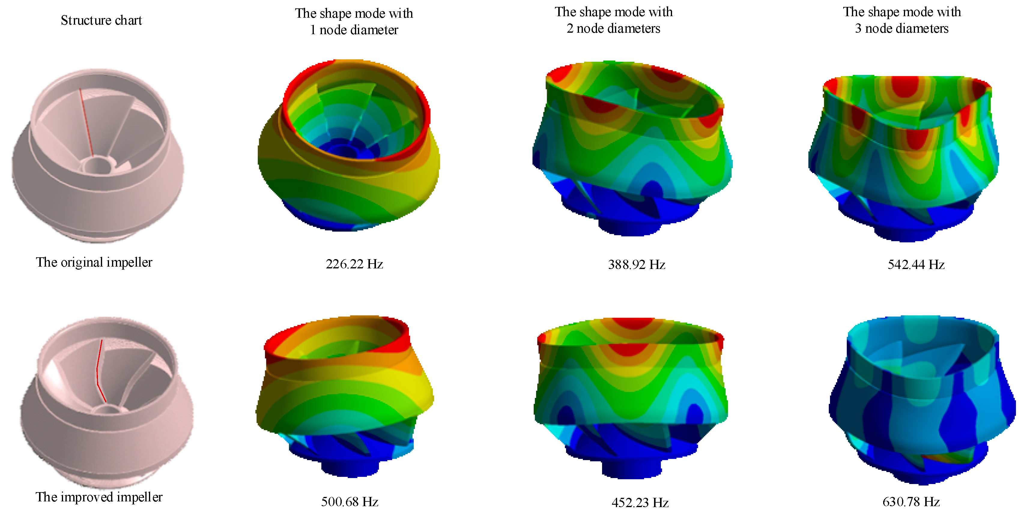
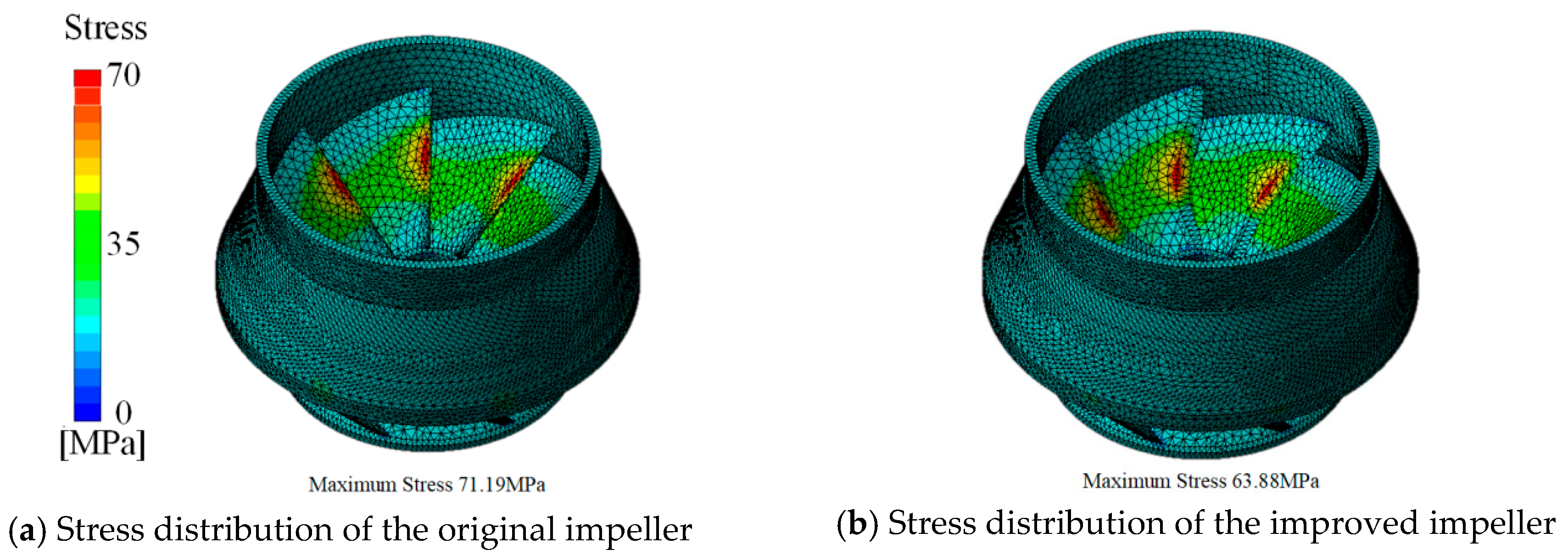
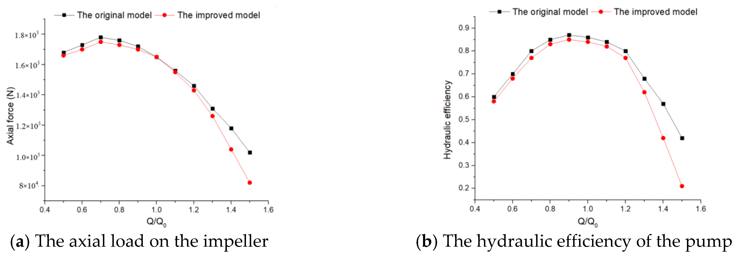
4.3. Improved Design of the RCP Impeller

Due to the inconstancy of the hydraulic load around RCP impeller, natural frequencies of the impeller vary within a certain range. Therefore, in order to prevent resonance during normal operation, it is necessary to keep a large gap between the natural frequency of the impeller and the frequency of fluctuating pressure. Although redetermining the blade numbers of the impeller and vane diffuser can change both the node-diameter number of resonant mode and the excitation frequency, it may have a huge influence on the hydraulic performance of the RCP. Likewise, if the impeller hub structure is modified, other hydraulic components that cooperate with the impeller should be redesigned.
Natural frequencies of the impeller can be adjusted by modifying blade shape. There are several methods that can be employed, but a few of them are not recommendable for some reasons. For instance, the change of blade outlet edges affects the head, and the change of blade three-dimensional twist shape affects the efficiency. In the above chapter, there is a conclusion that hydraulic load affects natural frequencies. As can be seen from Figure 5 (red circle), the pressure difference between the pressure surface and suction surface at the inlet of the blade is larger than those in other areas. Therefore, cutting the blade inlet edges might be a viable way to alter natural frequencies. Besides, this method will not significantly affect hydraulic performance.
Cutting the blade inlet edges is brought forward to modify the impeller. The maximum indentation is in the middle of the edges, and its value is one tenth of the inlet diameter. The impact of this measure on natural vibration modes of the impeller was analyzed, and the performance of the pump was calculated. Figure 6 shows natural vibration modes of the impeller before and after the improvement. All three natural frequencies increase, and especially, one nodal diameter natural frequency is more than twice the original value. The three nodal diameters mode natural frequency of the new impeller is 16.3% larger than that of the original impeller, so this measure can effectively prevent hydraulic resonance.
It can be seen from Figure 5 that pressure difference between two sides of inlet edges is larger than that of other areas. So hydraulic load stress is concentrated in the middle of inlet edges. Figure 7 shows the stress distribution diagrams. After improvement, the maximum stress is reduced, and the structural strength of the blade is enhanced. Figure 8 shows the hydraulic performance curves before and after improvement. Cutting blade inlet edges have little effect on hydraulic performance. In cavitation performance, though Net Positive Suction Head (NPSH) of the pump is reduced from 61 m to 52 m. Because of the high-pressure (15.5 MPa) environment inside RCP, NPSH of the new design still meets performance requirements.
In summary, cutting the blade inlet edges is a solution of altering natural frequencies of the impeller without affecting hydraulic performance greatly. Since natural frequencies of the underwater impeller are subject to hydraulic load, relieving the stress concentration may increase natural frequencies. Therefore, the area where the load is concentrated has a great influence on the self-vibration model of the impeller, and redistributing hydraulic load can be used to improve the dynamic characteristic of the underwater rotating system.

5. Conclusions

This study analyzes the influence of three factors on natural frequencies of the RCP impeller and proposes a method of altering the natural impeller frequencies. The significance is:
(1)
This study provides a measure for testing vibration signals of an underwater rotator, and establishes a coupled simulation platform for modal analysis of the underwater impeller. Through comparative research, it is found that added mass and hydraulic load have a great influence on natural frequencies of the RCP impeller, but the impact of centrifugal force on them can be ignored. Therefore, it is necessary to take both added mass and hydraulic load into account for modal analysis of the impeller.
(2)
Since hydraulic load stress concentration occurs in the middle of inlet edges, a solution of cutting inlet edges of blades is proposed to change natural frequencies the impeller. Without affecting hydraulic performance significantly, the measure can prevent hydraulic resonance and enhance structural strength. This indicates that it is feasible to alter the self-vibration mode of the impeller by hydraulic load redistribution.
The method and results of this study are also applicable to other industrial pumps. However, there are still some research points that need to be studied further. For example, when an impeller rotates in liquid, its mechanical properties will change. Stress distribution characteristics of the impeller in this state are worth studying. In addition, it is of significance to research the effects of other hydraulic components on the self-vibration mode of the impeller.

Author Contributions

Conceptualization, J.W. and X.R.; methodology, P.W.; software, X.Z.; validation, J.W.; writing—original draft preparation, J.W. and P.W.; writing—review and editing, X.R. and X.F.; funding acquisition, Z.X. and X.F.

Funding

This work was supported by the National Basic Research Program of China [Grant No. 2015CB057301], the Zhejiang Provincial Natural Science Foundation (Grant No. LQ18E060002), and the Science Fund for Creative Research Groups of the National Natural Science Foundation of China [Grant No.51521064].

Conflicts of Interest

The authors declare that they have no conflict of interest.

References

  1. Gao, H.; Gao, F.; Zhao, X.; Chen, J.; Cao, X. Transient flow analysis in reactor coolant pump systems during flow coastdown period. Nucl. Eng. Des. 2011, 2, 509–514. [Google Scholar] [CrossRef]
  2. Zhang, Y.; Wang, X.F.; Zhao, G.; Xu, S.L.; Ye, Z. Numerical Analysis of Pressure Fluctuations Caused by Impeller-Diffuser Interaction in a Mixed Flow Reactor Coolant Pump. In Proceedings of the 2011 Asia-Pacific Power and Energy Engineering Conference, Wuhan, China, 25–28 March 2011; pp. 1–4. [Google Scholar]
  3. Zhang, X.; Wang, P.; Ruan, X.; Xu, Z.; Fu, X. Analysis of pressure pulsation induced by rotor-stator interaction in nuclear reactor coolant pump. Shock Vib. 2017, 2017, 1–18. [Google Scholar] [CrossRef]
  4. Ma, B.M. Irradiation swelling, creep, thermal shock and thermal cycling fatigue analysis of cylindrical controlled thermonuclear reactor first wall. Nucl. Eng. Des. 1974, 1, 1–30. [Google Scholar] [CrossRef]
  5. Singh, M.P.; Thakur, B.K.; Sullivan, W.E.; Donald, G. Resonance Identification for Impellers. In Proceedings of the 32nd Turbomachinery Symposium, Houston, TX, USA, 8–11 September 2003. [Google Scholar]
  6. Valero, C.; Huang, X.; Egusquiza, E.; Farhat, M.; Avellan, F. Modal behavior of a reduced scale pump turbine impeller. Part II: Numerical simulation. IOP Conf. Ser. Earth Environ Sci. 2010, 12, 012117. [Google Scholar] [CrossRef]
  7. Liang, Q.W.; Rodríguez, C.G.; Egusquiza, E.; Escaler, X.; Avellan, F. Modal Response of Hydraulic Turbine Runners. In Proceedings of the 23rd IAHR Symposium on Hydraulic Machinery and Systems, Yokohama, Japan, 17–21 October 2006; pp. 42–48. [Google Scholar]
  8. Li, W. Modal and Response Analysis of Rotating Blade. Ph.D. Thesis, Harbin Engineering University, Harbin, China, 2008. [Google Scholar]
  9. Zhang, Y.T.; Wang, X.L.; Li, R.G. Experimental research on nature frequency of prestressed concrete beams. J. Huazhong Univ. Sci. Technol. Nat. Sci. Ed. 2007, 2, 12–15. [Google Scholar]
  10. Zhang, Y.F. Investigation on Effect of Adhesive Water Condition to Wet Modal Response of Nuclear Coolant Pump Impeller. Ph.D. Thesis, Dalian University of Technology, Dalian, China, 2015. [Google Scholar]
  11. Xu, S.; He, X.; Sun, T.; Wang, X. Research of Damping and Dynamic Stress for Impeller of Reactor Coolant Pump. In Proceedings of the ISROMAC 2017 (International Symposium on Transport Phenomena and Dynamics of Rotating Machinery), Maui, HI, USA, 16–21 December 2017; pp. 1–8. [Google Scholar]
  12. Bogdan, M. Measurement experiment, using NI USB-6008 data acquisition. J. Electr. Electr. Eng. 2009, 1, 117. [Google Scholar]
  13. Ewins, D.J.; Saunders, H. Modal Testing: Theory and Practice; Research Studies Press: Letchworth, UK, 1984; pp. 32–35. [Google Scholar]
  14. Antoni, J.; Randall, R.B. The spectral kurtosis: Application to the vibratory surveillance and diagnostics of rotating machines. Mech. Syst. Signal Process. 2006, 2, 308–331. [Google Scholar] [CrossRef]
  15. Trethewey, M.W.; Friell, J.C.; Chandra, M.J.; Lebold, M.S. A spectral simulation approach to evaluate probabilistic measurement precision of a reactor coolant pump torsional vibration shaft crack monitoring system. J. Sound Vibr. 2008, 4, 1036–1056. [Google Scholar] [CrossRef]
  16. Mathews, J.H.; Fink, K.D. Numerical Methods with MATLAB; Pearson Prentice Hall: Upper Saddle River, NJ, USA, 2010; pp. 152–164. [Google Scholar]
  17. Yuan, D.; Wang, P.; Wong, X.; Wu, X. Design and Numerical Simulation on Guide Vane of AP1000 Reactor Coolant Pump. In Proceedings of the International Conference on Consumer Electronics, Las Vegas, NV, USA, 9–12 January 2011; pp. 4016–4019. [Google Scholar]
  18. Thompson, D. Railway Noise and Vibration: The Use of Appropriate Models to Solve Practical Problems. In Proceedings of the 21st International Congress on Sound and Vibration, Beijing, China, 13–17 July 2014; pp. 1–16. [Google Scholar]
  19. Wang, Y.; Wang, P.; Tan, X.; Xu, Z.; Ruan, X. Research on the non-uniform inflow characteristics of the canned nuclear coolant pump. Ann. Nucl. Energy 2018, 115, 423–429. [Google Scholar] [CrossRef]
  20. Zhang, Y.; Wang, X.; Jie, H.E. Effect of boric acid concentration on reactor coolant pump performance in PWRs. Nucl. Power Eng. 2011, 4, 95–98. [Google Scholar]
  21. Guo, Z.; Cao, H.; Ma, Q.; Yi, F.; Du, S. Relationship between rotor/vanes blade number and modal diameter number of bladed-disk coupling vibration. J. Aerosp. Power. 2019, 1, 99–105. [Google Scholar]
  22. Gerolymos, G.A.; Michon, G.J.; Neubauer, J. Analysis and application of chorochronic periodicity in turbomachinery rotor/stator interaction computations. J. Propuls. Power. 2002, 6, 1139–1152. [Google Scholar] [CrossRef]
  23. Montante, G.; Lee, K.C.; Brucato, A.; Yianneskis, M. Numerical simulations of the dependency of flow pattern on impeller clearance in stirred vessels. Chem. Eng. Sci. 2001, 12, 3751–3770. [Google Scholar] [CrossRef]
  24. Bishop, R.E.D.; Johnson, D.C. The Mechanics of Vibration; Cambridge University Press: Cambridge, UK, 2011; pp. 72–85. [Google Scholar]
  25. Beards, C. Structural Vibration: Analysis and Damping; Elsevier: Amsterdam, The Netherlands, 1996; pp. 58–69. [Google Scholar]
Figure 1. Schematic diagram of the test bench. (1. Motor, 2. Frame, 3. Bearing, 4. Tank, 5. Slip ring, 6. Impeller, 7. Piezoelectric accelerometer, 8. Charge amplifier and NI Data Acquisition Card).
Applsci 09 04551 g001
Figure 2. Test signal spectrogram.
Applsci 09 04551 g002
Figure 3. Mesh diagram of the model ((a) Inlet pipe (b) Impeller (c) Vane diffuser (d) Volute).
Applsci 09 04551 g003
Figure 4. The map of static pressure distribution on the impeller surface.
Applsci 09 04551 g004
Figure 5. Pressure distribution on both sides of the blade at span = 0.5.
Applsci 09 04551 g005
Figure 6. Comparison of natural vibration modes before and after impeller improvement.
Applsci 09 04551 g006
Figure 7. Comparison of stress distribution before and after impeller improvement.
Applsci 09 04551 g007
Figure 8. Comparison of hydraulic performance before and after impeller improvement.
Applsci 09 04551 g008
Table 1. Natural frequencies of the impeller by simulation.
Nodal DiametersA. Static Impeller in the Air [Hz]B. Static Impeller in Water [Hz]C. Rotating Impeller in Water [Hz] (100 r/min)D. Rotating Impeller in the Air [Hz] (1800 r/min)
039423152.6−20.0%3363.6−14.7%39420%
12520.31974.2−21.7%2045.8−18.8%2517.7+0.001%
25817.75003.4−14.0%5604.2−3.7%5812.7+0.001%
Table 2. Impeller simulation settings.
ParameterValue
Turbulence modelK-epsilon
Convergence precision<1 × 10⁻⁵
Rated speed of impeller1800 r/min
Inlet volume flowrate17,886 m3/h
Outlet static pressure15.5 MPa

