Article

A Waste Heat-Driven Cooling System Based on Combined Organic Rankine and Vapour Compression Refrigeration Cycles

School of Engineering, University of Glasgow, Glasgow G12 8QQ, UK
*
Author to whom correspondence should be addressed.
Appl. Sci. 2019, 9(20), 4242; https://doi.org/10.3390/app9204242
Submission received: 11 September 2019 / Revised: 30 September 2019 / Accepted: 9 October 2019 / Published: 11 October 2019
(This article belongs to the Section Energy Science and Technology)

Abstract

:
In this paper, a heat driven cooling system that essentially integrated an organic Rankine cycle power plant with a vapour compression cycle refrigerator was investigated, aiming to provide an alternative to absorption refrigeration systems. The organic Rankine cycle (ORC) subsystem recovered energy from the exhaust gases of internal combustion engines to produce mechanical power. Through a transmission unit, the produced mechanical power was directly used to drive the compressor of the vapour compression cycle system to produce a refrigeration effect. Unlike the bulky vapour absorption cooling system, both the ORC power plant and vapour compression refrigerator could be scaled down to a few kilowatts, opening the possibility for developing a small-scale waste heat-driven cooling system that can be widely applied for waste heat recovery from large internal combustion engines of refrigerated ships, lorries, and trains. In this paper, a model was firstly established to simulate the proposed concept, on the basis of which it was optimized to identify the optimum operation condition. The results showed that the proposed concept is very promising for the development of heat-driven cooling systems for recovering waste heat from internal combustion engines’ exhaust gas.

1. Introduction

Internal combustion (IC) engines have been the primary power source for automobiles, long-haul trucks, locomotives, and ships over the past century [1]. Over this time, periods of high fuel costs and concerns about foreign oil dependence have resulted in increasingly complex engine designs to reduce fuel consumption [2]. Although the most efficient mode of the modern large diesel engines is about 48–51% efficient in utilising the fuel energy [3], the remainder is still lost as waste to the environment through exhaust gas and jacket water. It appears that developing concepts for utilising the waste heat is important in the area of IC engine application.
Current interest in reducing emissions and engine operating costs has led to the use of efficient waste heat recovery (WHR). For marine engines, the waste heat was originally used for direct heating services, including space heating in winter [4], heavy fuel oil (HFO) heating [5], ballast water heating [6], and hot water supply. However, the heating loads needed for shipboard service on a conventional vessel are usually much less than the available waste heat, resulting in a large amount of heat being unused.
WHR technology for power production was then proposed to be coupled with the power propulsion plants or to meet the demand for auxiliary services without additional fuel costs and zero associated CO2 emissions. Steam-based WHR systems for both four- and two-stroke marine engines are available commercially, among others by MAN, ABB, Wärtsilä, Mitsubishi heavy industries, and Cummins [3]. Some work on marine WHRs has been reported in the past few years. The work conducted by Theotokatos and Livanos analysed a single pressure steam Rankine cycle (SRC) for a marine engine WHR [7], finding that the WHR is more attractive to combine with two-stroke IC engine than four-stroke IC engine from an economic perspective [8]. Altosole et al. [9] compared SRC-WHRs of a new design with a retrofitting one on board a passenger ship equipped with diesel–electric propulsion. Benvenuto et al. [10] studied a dual pressure SRC as a WHR system of a two-stroke diesel engine used for the propulsion of a tanker.
As the exhaust gas temperature of marine engines is usually lower than 370 °C, it is economically unviable to operate a steam Rankine cycle system [11]. Organic Rankine cycle (ORC) has since been proposed as an alternative solution for two-stroke engines because of their low exhaust temperatures. Singh [12] conducted a review of different waste heat recovery systems for power generation, including Rankine cycle, Kalina cycle, exhaust gas turbine system, thermoelectric generation system, and the combination of these technologies, focusing on the utilisation of WHR for the supply of mechanical/electrical power to the ship. Baldi and Gabrielii [13] made comparisons between SRC, ORC, and Kalina cycle for marine WHR, and indicated that ORC produced about 7% additional power and that the SRC and Kalina cycles produced about 5% additional power. A comparison between ORC and conventional steam Rankine cycle was conducted by Andreasen et al. [14], which showed that ORC has better performance, as higher turbine efficiencies can be achieved for the ORC compared with the steam Rankine cycle system. These studies aimed to explore the ORC system’s potential as an alternative to SRC and demonstrated its potential to improve fuel efficiency at relatively low engine exhaust temperatures.
Apart from heating and electricity, cooling is also required for food preservation and air conditioning, especially for cruise ships. Thermally powered cooling technologies have gained considerable interest. Liang et al. [15,16,17] proposed an electricity-cooling combined system (ECCS) for waste heat recovery of marine engines, in which the condensation heat of SRC is used to heat the generator of the absorption refrigeration cycle. Some scholars proposed to integrate power with cooling cycles, in which the ammonia mixture is used as the working medium [18,19,20].
In addition to the absorption refrigeration cycle, vapour compression cycle refrigerator is another technology that requires mechanical power/electricity to drive the compressor. Therefore, the concept of combining ORC and vapour compression cycle (VCC) was proposed as an alternative heat-driven refrigeration technology by Prigmore and Barber [21]. Compared to the thermally powered absorption cooling technologies, the ORC-VCC has some potential advantages in terms of performance and simplicity. Furthermore, the VCC powered by an ORC can make use of the heat source throughout the year [22] to provide either cooling or electricity when cooling is not required [23], increasing the operational flexibility and improving the economic profitability. Great efforts have been devoted to the development of ORC-VCC systems since such a concept was proposed. Wali [24,25] compared the performance of solar powered ORC-VCC systems for building cooling applications with five different working fluids. R113 and FC88 were considered as the best working fluids. To reduce the system complexity, Aphornratana and Sriveerakul [26] proposed an ORC-VCC concept, of which the compressor and expander are integrated in the same unit, use the same working fluid, and share the same condenser. Bu et al. [27,28,29] carried out a series of investigations on the working fluid of ORC-VCC ice makers and found that R600 is the most suitable working fluid. An experimental test on the ORC-VCC system was conducted by Wang [23], and reported a coefficient of performance (COP) of 0.48. Biancardi et al. [30] introduced the design, fabrication, and test of a solar-powered organic Rankine cycle heat pump and chiller system capable of delivering 63.3 kW of heating and cooling. When R11 was used as the working fluid, the heating COP of the system ranged from 1.6 to 2.25, while the cooling COP varied between 0.5 and 0.75. In addition to the above studies, several other researchers [31,32,33,34,35] have also reported the performance of the ORC-driven VCC for heating purposes.
Despite numerous studies on individual WHR technologies for marine diesel engines, the effect of transmission ratio on the performance of the thermodynamic WHR has not been tackled thus far. In this paper, a marine engine waste heat recovery and cooling system with combined ORC and VCC is proposed. A comprehensive energy and exergy analysis was carried out and the potential of the proposed thermodynamic system was demonstrated.

2. Thermodynamics and Operational Conditions of the Proposed System

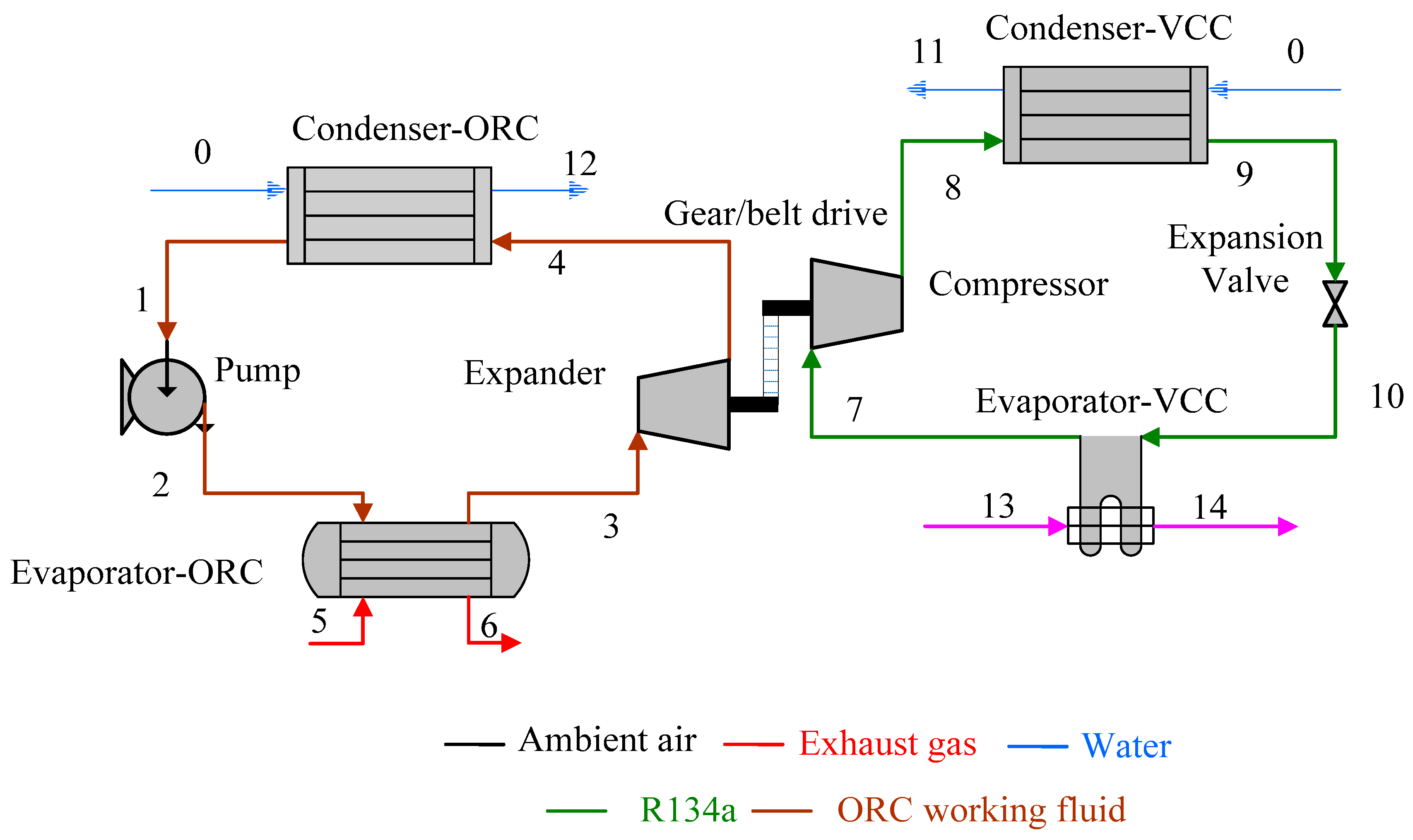
2.1. System Components

Figure 1 shows a schematic of the proposed heat driven cooling system in the paper. As shown in the figure, the ORC expander was coupled with the VCC compressor by using a transmission unit. The combined system aimed to produce cooling for refrigeration cabinets by waste heat recovery from engines. The thermodynamic states of the combined organic Rankine cycle-vapour compression cycle (ORC-VCC) are shown in the Temperature-Entropy (T-S) diagrams in Figure 2. Here, a 12-cylinder Wärtsilä RT-flex96C engine with 68640 kW rated power was selected. The exhaust temperature and heat energy contained in the exhaust gas of the engine is presented in Figure 3. It was observed that the temperature peak appeared at 40% contract maximum continuous rating (MCR) and that heat content increased with the engine load. The exhaust gas temperature was in a range of 528.5 K to 597.9 K, and the energy contained in the gas varied from 11,860 to 35,787 kW.
The system was subject to two working conditions: (1) a belt drive was adopted, and the transmission ratio was adjusted by changing the diameter of the pulley when the transmission ratio was not equal to 1; (2) the ORC expander and the compressor shared a common shaft and the transmission ratio was set to 1.

2.2. Thermodynamics Models and Equations

To establish a thermodynamics model for the system proposed, a number of assumptions were made, such as (1) both the ambient temperature and the sea water temperature were 298 K; (2) the pinch point was 30 K in the evaporator of the ORC and was 5 K in the other heat exchangers; (3) the isentropic efficiency of the expander, compressors, and pump was 0.7, 0.7, and 0.8, respectively; (4) the temperature of the exhaust gas exiting boiler was higher than the acid dew point of 393 K [36]; (5) both heat and pressure loss in all heat exchangers and pipes were assumed to be negligible; (6) the combined cycles were operated under steady state conditions; (7) the mechanical loss of the expander/compressor coupling was negligible.

2.2.1. Components of the Exhaust Gas

Assuming that the molecular formula of hydrocarbons in the heavy fuel oil (HFO) supplied to the main IC engine was C30H62 [37], the chemical equation of the combustion process can be expressed as the following equation:
C 30 H 62 + a ( O 2 + 3.76 N 2 ) 30 C O 2 + 31 H 2 O + b O 2 + 3.76 a N 2 .
Considering that the oxygen concentration in the exhaust gas was 15.3% [38], the molar concentration of the exhaust gas composition was then calculated: 75.37% for nitrogen, 5.37% for carbon dioxide, 2.27% for steam (vapour), and 15.3% for oxygen. The properties of the exhaust gas can be evaluated on the basis of the mixing rule proposed by Poling [39].

2.2.2. Thermodynamics Equations

First law modelling
(1) Pump (1→2):
The power consumed by the pump can be calculated as
W p u m p = m f 1 ( h 2 h 1 ) .
The isentropic efficiency of the pump can be calculated as
η p u m p , i s = h 2 i s h 1 h 2 h 1 .
(2) Evaporator-ORC (2→3, 5→6):
The heat transferred in the evaporator-ORC can be calculated as
Q e v a , O R C = m f 1 ( h 3 h 2 ) ,
Q e v a , O R C = m g ( h 5 h 6 ) .
(3) Expander (3→4):
The power generated in the expander can be calculated as
W e x p = m f 1 ( h 3 h 4 ) .
The isentropic efficiency of the expander can be calculated as
η e x p , i s = h 3 h 4 h 3 h 4 i s .
(4) Condenser-ORC (4→1, 0→12):
The heat transferred in condenser-ORC can be calculated as
Q c o n d , O R C = m f 1 ( h 4 h 1 ) ,
Q c o n d , O R C = m w 1 ( h 12 h 0 ) .
(5) Compressor (7→8):
The power consumed by compressor can be calculated as
W c o m = m f 2 ( h 8 h 7 ) ,
W c o m = W e x p .
The isentropic efficiency of the compressor can be calculated as
η c o m , i s = h 8 i s h 7 h 8 h 7 .
(6) Condenser-VCC (8→9, 0→11):
The heat transferred in the condenser-VCC can be calculated as
Q c o n d , V C C = m f 2 ( h 8 h 9 ) ,
Q c o n d , V C C = m w 2 ( h 11 h 0 ) .
(7) Expansion valve (9→10):
The working fluid flowing through the expansion valve can be taken as an isenthalpic throttling process
h 9 = h 10 .
(8) Evaporator-VCC (10→7, 13→14):
The heat transferred in the evaporator-ORC can be calculated as
Q e v a , V C C = m f 2 ( h 7 h 10 ) ,
Q e v a , V C C = m a i r ( h 13 h 14 ) .
Second law efficiency
The exergy at state point i in the system can be defined by
E i = m f [ ( h i h 0 ) T 0 ( s i s 0 ) ] .
The exergy destruction caused in each component can be calculated as
I i = E i n E o u t .
Expressions for exergy destruction are shown in following:
Pump-ORC:
I p u m p , O R C = W p u m p + E 1 E 2 .
Evaporator-ORC:
I e v a , O R C = E 5 + E 2 ( E 6 + E 3 ) .
Expander-ORC:
I e x p , O R C = E 3 E 4 W e x p .
Condenser-ORC:
I c o n d , O R C = E 0 + E 4 ( E 1 + E 12 ) .
Compressor-VCC:
I c o m , V C C = W c o m + E 7 E 8 .
Condenser-VCC:
I c o n d , V C C = E 8 + E 0 ( E 11 + E 9 ) .
Expansion Valve:
I v a l , V C C = E 9 E 10 .
Evaporator-VCC:
I e v a , V C C = E 10 + E 13 ( E 7 + E 14 ) .
The total exergy destruction caused in this system can be expressed as
I t o t a l = I e v a , O R C + I e x p , O R C + I p u m p , O R C + I c o n d , O R C + I c o n d , V C C + I v a l , V C C + I e v a , V C C + I c o m , V C C .
The exergy efficiency of the ORC-VCC waste heat recovery system can be calculated as the following:
η e x W H R = E o u t / E i n .
In this case, the exergy input Ein included the exergy difference of exhaust gas stream, the power of the pump.
E o u t = ( T 0 / T c a b i n , i n 1 ) Q e v a V C C ,
E i n = E e x h + W P u m p .
The term EER (energy efficiency ratio) is a ratio of the useful cooling provided to the work required of air conditioners. Higher EER equates to lower operating costs.
E E R = Q e v a , V C C W e x p .

2.3. Operational Conditions

The heat transfer process should meet two requirements simultaneously. Firstly, the pinch point temperature difference (PPTD) should not be lower than 30 K in the modelling of ORC evaporator during the phase change process to ensure the feasible heat exchanger design in practical applications. Furthermore, the exhaust gas temperature should be higher than the acid dew point to avoid the possible corrosion in the evaporator (exhaust side), which is normally taken to be 393 K [40,41].
Figure 4 shows the evaporation process based on the PPTD method, which has been explained in our previous study [35]. During the evaporation process, the evaporation temperature of working fluid rises as the pressure increases. For a working fluid with higher critical temperature, when ORC operates at T3a, the relative exhaust gas temperature T6a after heat transfer is above 393 K. In this case, the heat transferred in the evaporator will become smaller as the evaporation pressure increases, which would lead to a reduction of power output.
However, for a working fluid with low critical temperature, the temperature during the evaporation process varies from T2 to T3b. As a result, the exhaust gas temperature would be lower than 393 K on the basis of the assumption that the PPTD is 30 K. To avoid a possible corrosion problem in the ORC evaporator, the outlet temperature of exhaust gas after heat transfer is set to be 393 K. In this case, the heat content in the ORC evaporator remains the same, even the evaporation pressure varies. On the other hand, as the evaporation pressure increases, the flow rate of working fluid decreases and the energy density becomes greater.
A program developed on the basis of the MATLAB platform was adopted to analyse the thermodynamic performance. Four environmentally friendly working fluids—R1233zd, R1234zez, R245fa and R245ca—were considered as the ORC working fluids for the performance comparison, and the refrigerant R134a was used in the VCC. Their enthalpies and entropies of were obtained by using a database Refprop 9.0.

3. Results

3.1. Belt Drive as the Transmission Unit

When a belt drive was used as the transmission unit for the coupling of expander and compressor, both the ORC and VCC could be operated at their optimum conditions simultaneously. In this case, the transmission ratio could be adjusted by changing the diameters of two pulleys.
As the refrigeration cycle was powered by the ORC expander, the variation of the ORC power output had a great effect on the performance of the refrigeration cycle. Figure 5 presents the comparison of ORC power output among the four different working fluids. The figure shows that for R1233zd and R1234zez, the power output firstly increases and then decreases after reaching its peak value roughly at 34oo kPa. This is because enthalpy change across the expander increased as the evaporation pressure increases. However, the mass flow rate of working fluid decreases as the ORC evaporation pressure increases. As a result, the different variation trends of these two parameters lead to an optimal power output when the ORC was operated nearly at the critical pressure. For the working fluids with lower critical temperatures, such as R245fa and R245ca, the maximum cooling capacity appeares at a higher evaporation pressure, whereas it appeares at a lower evaporation pressure for the working fluids with lower critical temperatures, namely, R1233zd and R1234zez. Furthermore, it can be observed that R1233zd and R245ca have a higher power output in comparison with R1234zez and R245fa.
In this system, the power generated in the ORC expander was consumed by the VCC compressor. Hence, the sole useful energy output of the whole system was the cooling generated in the VCC. Figure 6 shows the variation of cooling capacity and EER with evaporation pressure. The cooling capacity has a similar variation trend with that of the ORC power output, as shown in Figure 5. This is because the power consumed by the VCC compressor is equal to that generated by the ORC expander. For a given condensation temperature, the power input into the VCC decides the mass flow rate of the refrigerant in the VCC. In other words, the cooling capacity is decided by the power input of the VCC.
Figure 6 also indicates that the EER decreases with the ORC evaporation pressure. According to Equation (32), EER is defined as the cooling capacity of evaporation in the VCC to the power generated by the ORC. As the ORC evaporation pressure increases, more power is supplied to the VCC subsystem, and the cooling capacity of the evaporator also increases because of the increasing refrigerant flow in VCC. This can be attributed to the fact that the power consumed by the compressor increased, although the cooling capacity also rises. The growth rate of the cooling capacity is not comparable to that of the compressor power, resulting in a smaller EER.
Figure 7 shows the variation of exergy efficiency when the ORC is operated under different evaporation pressures. In this system, the exergy output refers to the cooling exergy of the evaporator in the VCC, and the exergy input consists of the heat exergy of the evaporator in the ORC and the pump power. At the same evaporation temperature, the variation trend of exergy efficiency in Figure 6 is similar to that of the cooling capacity. This is because the exergy output of cooling is linearly correlated to the cooling capacity at a given VCC evaporation temperature. Furthermore, a higher ORC evaporation pressure leads to a better temperature match between the organic working fluid and the exhaust gas, and the exergy destruction per mass unit decreases.

3.2. Sharing a Common Shaft

In this section, the case where the expander and compressor shared a common shaft is studied, wherein the transmission ratio was 1. The marine engine is operated under 100% MCR. From the above analysis, R245ca and R1233zd show comparable performance. R1233zd is selected as the ORC working fluid because it is more environmentally friendly than R245ca. The ORC condensation temperatures are set as 308 K by using sea water as the heat sink. In this system, the pressure difference across the expander is equal to that across the compressor (P3-P4 = P8-P7).
Figure 8 shows the variation of cooling capacity under different VCC evaporation temperatures. It can be seen that the cooling capacity decreases with ORC evaporation pressure and increased with the cold air temperature. With the increase of the ORC evaporation pressure, the VCC condensation pressure is enhanced for a fixed PPTD and a constant heat sink, resulting in a higher discharged temperature. The enthalpy difference across the compressor outlet and inlet become greater. Consequently, the cooling capacity of the VCC evaporator is reduced because of the decreasing flow rate of the VCC refrigerant.
The calculated EER of cooling strongly depends on the operating conditions, especially absolute temperature and the temperature difference between the heat sink and the target refrigeration temperature. Figure 9 illustrates that the EER of cooling decreases with ORC evaporation pressure. For a given heat sink temperature, the VCC condensation pressure and temperature rise when the ORC evaporation pressure is increased. In that case, the temperature lift of the refrigerant between the condenser and the evaporator is enhanced, resulting in a decreased EER.
In this system, both ORC and VCC used sea water as the heat sink. The effect of condensation temperature on the performance of both the ORC power cycle and the VCC refrigeration cycle was analysed. The condensation temperatures in both subsystems were assumed to be the same, as they both used the same heat sink. The curves in Figure 10 present an ascending trend as the condensation temperature increases. By sharing a common shaft, the pressure difference between the ORC expander inlet and outlet is equal to that between the compressor outlet and inlet, which can be expressed as P3-P4 = P8-P7.
The variation of ORC condensation temperature influences the ORC and VCC. When the ORC is operated at the same evaporation pressure, the pressure difference across the expander is reduced if the condensation temperature is increased. As a result, the VCC evaporation pressure P7 was decreases, as the VCC expander outlet pressure P8 increases with the VCC condensation temperature, explaining why the evaporation temperature increased with the condensation temperature.
From Figure 10, it can be concluded that the ORC subsystem should be operated at a higher evaporation pressure to achieve a lower required refrigeration temperature.
Figure 11 shows the variation of the cooling capacity with variable condensation temperatures. It can be observed that the cooling capacity increases with rising condensation temperature. For the ORC subsystem, the expander could generate less power output to drive the VCC compressor. In the VCC subsystem, the power consumed by per unit mass refrigerant in the VCC is reduced because the pressure difference across the compressor decreases with the increase of condensation temperature, as mentioned above. The enthalpy difference of the refrigerant at the compressor outlet and inlet decreases as well, leading to a larger mass flow rate of refrigerant. Furthermore, the evaporation temperature becomes higher, explaining why the cooling capacity becomes larger for a higher condensation temperature, although the power provided by the ORC expander decreases.
Figure 12 shows the contribution of each component on the exergy destruction under different condensation temperatures in the condenser. It is evident that under the operating conditions considered, the evaporator in the ORC power cycle contributes the most significant part of the total exergy loss in the system. This result can be attributed to the significant irreversibility associated with heat transfer across the large temperature differences in the evaporator.
In the VCC subsystem, the irreversibility across the compressor is the maximum under most working conditions. However, the exergy destruction in the compressor is higher than that when the condensation temperature is lower than 309.65 K and Peva = 1100 kPa. This suggests that in order to improve the performance of the proposed system, special attention should be paid to reducing the irreversibility that exists in these components during machine design.
The irreversibility of the compressor and expander essentially depends on their isentropic efficiency; thus, their proper design can reduce this irreversibility. In particular, in order to reduce the irreversibility of the condenser and evaporator, they should be designed in such a way that the temperature difference between the fluids can be maintained as small as possible.
Figure 13 shows the variation of exergy efficiency when the condensation temperature varies. Regarding the exergy input, it consistes of heating exergy of the exhaust gas and pump power input. The temperature of exhaust gas T6 calculated by using the PPTD method is lower than 393 K, but it is set to be a constant of 393 K to avoid the possible corrosion problems. Therefore, the heat input is the same, although the condensation temperature changed under considered conditions. Moreover, less pump power is required for a rising condensation temperature.
Regarding the useful exergy output, the cooling exergy is found to be reduced at its higher VCC evaporation temperature, explaining the reason as to why the exergy efficiency declines as the condensation temperature increases, except at Peva = 1100 kPa.
For Peva = 1100 kPa, the exergy destruction of the expansion valve decreases sharply when the condensation temperature increases from 309.2 to 309.7 K (see Figure 12d), and a valley value at 309.7 K appeared, explaining why there is the maximum exergy efficiency under this condition.
Furthermore, it can also be observed that a higher exergy efficiency could be obtained when the ORC power systemis operated at a higher evaporation pressure. This is because the evaporation temperature in the VCC is much lower, as shown in Figure 9.
Table 1 summarises the optimal working conditions when the required cold air temperature is not higher than 263 K for a given heat sink temperature of 298 K. It can be understood that the belt drive transmission unit could result in the maximum cooling output of 9823 kW. Unfortunately, its ORC evaporation is 3500 kPa, which is much higher than that of the transmission unit sharing a common shaft. It is obvious that a thermo-economic evaluation is needed to decide which transmission unit is the best by making a trade-off between the thermodynamic performance and the compactness/reliability of the ORC-VCC combined system.

4. Discussion

Because exhaust gas temperature varies significantly when the engine loads change, it is essential to study the potential of the WHR system under different engine loads. The layout sharing a common shaft is considered for its simple structure, especially for transportation. R1233zd and R134a are used in the ORC and VCC, respectively. By considering the influence of the engine load on the operation of the ORC-VCC WHR system, an evaluation of the performance was conducted in this paper with respect to the cooling output at the same temperature. The following analysis is based on the flowing operating conditions. The ambient temperature and the sea water (heat sink) are both 298 K, the refrigeration temperature T15 is 263 K, which is low enough for both air conditioning and food preservation. The condensation ranges from 309 to 313 K, and the low temperature is limited by the heat sink temperature. The ORC evaporation pressure is the optimal pressure of 900 kPa listed in Table 1.
Figure 14 shows the cooling capacity of ORC-VCC when the engine is operated under different loads. It is noted that a higher cooling output could be achieved when increasing the engine. The waste heat recovery is closely related to the thermal properties of the heat source. As shown in Figure 2, the heat energy available for recovery increases with the engine load. The higher the temperature, the better the quality of the heat energy, and there is a peak temperature at 40% MCR. These two factors resulted in an upward trend for the ORC power output, and a sharp change appeares at 40% MCR. This variation trend is then transmitted to the cooling capacity in VCC, as it is powered by the ORC expander.
Figure 14 also shows that the cooling capacity increased with the condensation temperature. However, the condensation temperature is limited by the parameters of sea water, including its temperature and flow rate. The operational condition of the combined cycle could be controlled by adjusting the ORC operation pressure and the flow rate of the heat sink and heat sources according to the cooling demand on ship.

5. Conclusions

A refrigeration system that essentially integrates an ORC power cycle and a vapour compression refrigeration combined cycle by waste heat recovery of the marine engine was modelled and analysed in this paper. The thermal energy of the exhaust gas of an engine was recovered by the ORC power cycle to drive a compressor in the VCC. On the basis of comprehensive energy and exergy analyses, the influence of transmission ratio between the expander and the compressor on system performance was clarified. It was shown that both ORC and VCC could be operated under their optimal operational conditions simultaneously with the maximum 9823 kW cooling capacity at 263 K cold temperature in terms of the belt drive transmission unit. Although the transmission unit sharing a common shaft was more compact and reliable than the belt drive unit, the ORC and VCC could not be operated at their optimal conditions at the same time, leading to a lower cooling capacity. The ORC evaporator contributed the most significant part of the exergy loss in the ORC-VCC combined system because of its significant irreversibility associated with heat transfer across large temperature differences. The cooling capacity showed an upward trend with increasing engine load. A sharp change appeared at 40% MCR because of the high temperature in the exhaust gas. The thermo-economic evaluation of the system and corresponding experimental validations will be conducted in the future work.

Author Contributions

Y.L. built the model of the combined ORC-VCC cycle, analysed the results and write the whole papers. Z.Y. provided the supervision of the paper writing and revision. W.L. participated in the paper revision. All the authors read and approve the manuscript.

Funding

Engineering and Physical Sciences Research Council: EP/N020472/1, Engineering and Physical Sciences Research Council: EP/N005228/1, Engineering and Physical Sciences Research Council: EP/R003122/1, Engineering and Physical Sciences Research Council: EP/P028829/1

Acknowledgments

This research was funded by Engineering and Physical Sciences Research Council (EP/N020472/1, EP/N005228/1, EP/R003122/1, and EP/P028829/1) in the United Kingdom. We gratefully acknowledge the assistance of Hongyang Li in proofreading.

Conflicts of Interest

The authors declare no conflict of interest.

Abbreviations

Nomenclature
ICInternal combustion
ECCSElectricity-cooling combined system
MCRContract maximum continuous rating
COPCoefficient of performance
EEREnergy efficiency ratio
HFOHeavy fuel oil
PPTDPinch point temperature difference
ORCOrganic Rankine cycle
SRCSteam Rankine cycle
VCCVapour compression cycle
WHRWaste heat recovery
Symbols
EExergy (kW)
hSpecific enthalpy (kJ/kg)
IExergy destruction
mMass flow rate (kg/s)
QHeat (kW)
TTemperature (K)
WPower (kW)
ηEfficiency
Subscript
condCondenser
expExpander
exhExhaust gas
comCompressor
evaEvaporator
exExergy
inInput
isIsentropic process
f1Working fluid in ORC
f2Working fluid in VCC
pumpFluid pump
outOutput
wWater
0Reference environment

References

  1. UNEP. Green Economy in a Blue World; Synthesis Report; The WordFish Center Working Papers: Geneva, Switzerland, 2012. [Google Scholar]
  2. Tsitsilonis, K.M.; Theotokatos, G. A novel systematic methodology for ship propulsion engines energy management. J. Clean. Prod. 2018, 204, 212–236. [Google Scholar] [CrossRef] [Green Version]
  3. Shu, G.; Liang, Y.; Wei, H.; Tian, H.; Zhao, J.; Liu, L. A review of waste heat recovery on two-stroke IC engine aboard ships. Renew. Sustain. Energy Rev. 2013, 19, 385–401. [Google Scholar] [CrossRef]
  4. Bidini, G.; di Maria, F.; Generosi, M. Micro-cogeneration system for a small passenger vessel operating in a nature reserve. Appl. Therm. Eng. 2005, 25, 851–865. [Google Scholar] [CrossRef]
  5. Tien, W.K.; Yeh, R.H.; Hong, J.M. Theoretical analysis of cogeneration system for ships. Energy Convers. Manag. 2007, 48, 1965–1974. [Google Scholar] [CrossRef]
  6. Rigby, G.R.; Hallegraeff, G.M.; Sutton, C. Novel ballast water heating technique offers cost-effective treatment to reduce the risk of global transport of harmful marine organisms. Mar. Ecol. Prog. Ser. 1999, 191, 289–293. [Google Scholar] [CrossRef] [Green Version]
  7. Theotokatos, G.; Livanos, G. Exhaust gas waste heat recovery in marine propulsion plants. In Sustainable Maritime Transportation and Exploitation of Sea Resources; CRC Press: Boca Raton, FL, USA, 2001; pp. 663–671. [Google Scholar]
  8. Theotokatos, G.; Livanos, G. Techno-Economical analysis of single pressure exhaust gas waste heat recovery systems in marine propulsion plants. Proc. Inst. Mech. Eng. Part M J. Eng. Marit. Environ. 2013, 227, 83–97. [Google Scholar] [CrossRef]
  9. Altosole, M.; Laviola, M.; Trucco, A.; Sabattini, A. Waste heat recovery systems from marine diesel engines: Comparison between new design and retrofitting solutions. In Maritime Technology and Engineering; CRC Press: Boca Raton, FL, USA, 2014; pp. 735–742. [Google Scholar]
  10. Benvenuto, G.; Trucco, A.; Campora, U. Optimization of waste heat recovery from the exhaust gas of marine diesel engines. Proc. Inst. Mech. Eng. Part M J. Eng. Marit. Environ. 2014, 230, 83–94. [Google Scholar] [CrossRef]
  11. Hung, T.C. Waste heat recovery of organic Rankine cycle using dry fluids. Energy Convers. Manag. 2001, 42, 539–553. [Google Scholar] [CrossRef]
  12. Singh, D.V.; Pedersen, E. A review of waste heat recovery technologies for maritime applications. Energy Convers. Manag. 2016, 111, 315–328. [Google Scholar] [CrossRef]
  13. Baldi, F.; Gabrielii, C. A feasibility analysis of waste heat recovery systems for marine applications. Energy 2015, 80, 654–665. [Google Scholar] [CrossRef] [Green Version]
  14. Andreasen, J.G.; Meroni, A.; Haglind, F. A comparison of organic and steam Rankine cycle power systems for waste heat recovery on large ships. Energies 2017, 10, 547. [Google Scholar] [CrossRef]
  15. Liang, Y.; Shu, G.; Tian, H.; Liang, X.; Wei, H.; Liu, L. Analysis of an electricity–cooling cogeneration system based on RC–ARS combined cycle aboard ship. Energy Convers. Manag. 2013, 76, 1053–1060. [Google Scholar] [CrossRef]
  16. Liang, Y.; Shu, G.; Tian, H.; Wei, H.; Liang, X.; Liu, L.; Wang, X. Theoretical analysis of a novel electricity–cooling cogeneration system (ECCS) based on cascade use of waste heat of marine engine. Energy Convers. Manag. 2014, 85, 888–894. [Google Scholar] [CrossRef]
  17. Liang, Y.; Shu, G.; Tian, H.; Sun, Z. Investigation of a cascade waste heat recovery system based on coupling of steam Rankine cycle and NH3-H2O absorption refrigeration cycle. Energy Convers. Manag. 2018, 166, 697–703. [Google Scholar] [CrossRef]
  18. Zhang, N.; Lior, N. Methodology for thermal design of novel combined refrigeration/power binary fluid systems. Int. J. Refrig. 2007, 30, 1072–1085. [Google Scholar] [CrossRef]
  19. Pouraghaie, M.; Atashkari, K.; Besarati, S.M.; Nariman-Zadeh, N. Thermodynamic performance optimization of a combined power/cooling cycle. Energy Convers. Manag. 2010, 51, 204–211. [Google Scholar] [CrossRef]
  20. Demirkaya, G.; Vasquez, P.R.; Goswami, D.Y.; Stefanakos, E.; Rahman, M.M. Analysis of a combined power and cooling cycle for low-grade heat sources. Int. J. Energy Res. 2011, 35, 1145–1157. [Google Scholar] [CrossRef]
  21. Prigmore, D.; Barber, R. Cooling with the Sun’s heat design consideration and test data for a Rankine cycle prototype. Sol. Energy 1975, 17, 185–192. [Google Scholar] [CrossRef]
  22. Wang, H.; Peterson, R.; Harada, K.; Miller, E.; Ingram-Goble, R.; Fisher, L.; Yih, J.; Ward, C. Performance of a combined organic Rankine cycle and vapor compression cycle for heat activated cooling. Energy 2011, 36, 447–458. [Google Scholar] [CrossRef]
  23. Wang, H.; Peterson, R.; Herron, T. Design study of configurations on system COP for a combined ORC (organic Rankine cycle) and VCC (vapor compression cycle). Energy 2011, 36, 4809–4820. [Google Scholar] [CrossRef]
  24. Wali, E. Working fluids for solar, Rankine-cycle cooling systems. Energy 1980, 5, 631–639. [Google Scholar] [CrossRef]
  25. Wali, E. Optimum working fluids for solar powered Rankine cycle cooling of buildings. Sol. Energy 1980, 25, 235–241. [Google Scholar] [CrossRef]
  26. Aphornratana, S.; Sriveerakul, T. Analysis of a combined Rankine-vapor-compression refrigeration cycle. Energy Convers. Manag. 2010, 51, 2557–2564. [Google Scholar] [CrossRef]
  27. Bu, X.; Wang, L.; Li, H. Performance analysis and working fluid selection for geothermal energy-powered organic Rankine-vapor compression air conditioning. Geotherm. Energy 2013, 1, 2. [Google Scholar] [CrossRef] [Green Version]
  28. Bu, X.B.; Li, H.S.; Wang, L.B. Performance analysis and working fluids selection of solar powered organic Rankine-vapor compression ice maker. Sol. Energy 2013, 95, 271–278. [Google Scholar] [CrossRef]
  29. Bu, X.; Wang, L.; Li, H. Working fluids selection for fishing boats waste heat powered organic Rankine-vapor compression ice maker. Heat Mass Transf. 2014, 50, 1479–1485. [Google Scholar] [CrossRef]
  30. Biancardi, F.R.; Sitler, J.W.; Melikian, G. Development and test of solar Rankine cycle heating and cooling systems. Int. J. Refrig. 1982, 5, 351–360. [Google Scholar] [CrossRef]
  31. Demierre, J.; Henchoz, S.; Favrat, D. Prototype of a thermally driven heat pump based on integrated Organic Rankine Cycles (ORC). Energy 2012, 41, 10–17. [Google Scholar] [CrossRef]
  32. Demierre, J.; Favrat, D.; Schiffmann, J.; Wegele, J. Experimental investigation of a Thermally Driven Heat Pump based on a double Organic Rankine Cycle and an oil-free Compressor-Turbine Unit. Int. J. Refrig. 2014, 44, 91–100. [Google Scholar] [CrossRef]
  33. Wan, X.; Cai, L.; Yan, J.; Ma, X.; Chen, T.; Zhang, X. Power management strategy for a parallel hybrid-power gas engine heat pump system. Appl. Therm. Eng. 2017, 110, 234–243. [Google Scholar] [CrossRef]
  34. Shang, S.; Li, X.; Wu, W.; Wang, B.; Shi, W. Energy-saving analysis of a hybrid power-driven heat pump system. Appl. Therm. Eng. 2017, 123, 1050–1059. [Google Scholar] [CrossRef]
  35. Liang, Y.; Al-Tameemi, M.; Yu, Z. Investigation of a gas-fuelled water heater based on combined power and heat pump cycles. Appl. Energy 2018, 212, 1476–1488. [Google Scholar] [CrossRef] [Green Version]
  36. Liang, Y.; Bian, X.; Qian, W.; Pan, M.; Ban, Z.; Yu, Z. Theoretical analysis of a regenerative supercritical carbon dioxide Brayton cycle/organic Rankine cycle dual loop for waste heat recovery of a diesel/natural gas dual-fuel engine. Energy Convers. Manag. 2019, 197, 111845. [Google Scholar] [CrossRef]
  37. Prevention of Air Pollution from Ships-Updated 2000 Study on Greenhouse Gas Emissions from Ships Phase 1 Report; MEPC 58/INF. 6; International Maritime Organization (IMO): London, UK, 2008.
  38. Technical File for Hyundai-Man B&W 12K98MC-C Mk6; Hyundai Heavy Industries Co., Ltd.: Ulsan, Korea, 2006.
  39. Poling, B.E.; Prausnitz, J.M.; O’Connell, J.P. The Properties of Gases and Liquids; McGraw-Hill: New York, NY, USA, 2001; Volume 5. [Google Scholar]
  40. Shu, G.; Liu, L.; Tian, H.; Wei, H.; Liang, Y. Analysis of regenerative dual-loop organic Rankine cycles (DORCs) used in engine waste heat recovery. Energy Convers. Manag. 2013, 76, 234–243. [Google Scholar] [CrossRef]
  41. Li, X.; Song, J.; Yu, G.; Liang, Y.; Tian, H.; Shu, G.; Markides, C.N. Organic Rankine cycle systems for engine waste-heat recovery: Heat exchanger design in space-constrained applications. Energy Convers. Manag. 2019, 199, 111968. [Google Scholar] [CrossRef]
Figure 1. Schematic of proposed organic Rankine cycle-vapour compression cycle (ORC-VCC) systems for waste heat recovery.
Applsci 09 04242 g001
Figure 2. Temperature-Entropy (T-S) diagrams of both the ORC and VCC.
Applsci 09 04242 g002
Figure 3. Temperature and heat content available in exhaust gas under different loads.
Applsci 09 04242 g003
Figure 4. The temperature-entropy diagram on both exhaust gas and working fluid during the heat transfer process based on the pinch point temperature difference (PPTD) method.
Applsci 09 04242 g004
Figure 5. Effects of ORC evaporation pressure on ORC power output for different working fluids.
Applsci 09 04242 g005
Figure 6. Effect of ORC evaporation pressure on cooling capacity and energy efficiency ratio for different working fluids.
Applsci 09 04242 g006
Figure 7. Effect of ORC evaporation pressure on exergy efficiency of combined cycle.
Applsci 09 04242 g007
Figure 8. Effect of ORC evaporation pressure on cooling capacity for the case of sharing a common shaft.
Applsci 09 04242 g008
Figure 9. Effect of ORC evaporation pressure on cooling capacity for the case of sharing a common shaft.
Applsci 09 04242 g009
Figure 10. Effect of condensation temperature in both condensers on evaporation for the case of sharing a common shaft.
Applsci 09 04242 g010
Figure 11. Effect of ORC condensation temperature on cooling capacity for the case of sharing a common shaft.
Applsci 09 04242 g011
Figure 12. Contribution of each component on exergy destruction under different condensation pressures.
Applsci 09 04242 g012aApplsci 09 04242 g012b
Figure 13. Effect of condensation temperature on exergy efficiency in the case of sharing a common shaft.
Applsci 09 04242 g013
Figure 14. Cooling capacity under different engine loads at 263 K required cooling temperature.
Applsci 09 04242 g014
Table 1. Optimal operational conditions at 263 K VCC evaporation temperature.
ParametersBelt DriveCommon Shaft
ORC working fluidR245caR1233zd
VCC refrigerantR134aR134a
Cooling capacity at 263K [kW]98236902
ORC evaporation pressure [kPa]3500900
Energy efficient ratio (EER)2.743.06
Power output of expander [kW]35842180
Total exergy destruction [kW]74828132
ORC thermal efficiency [%]13.799.10
Exergy efficiency [%]13.109.50

