Article

Damage Analyses of Replaceable Links in Eccentrically Braced Frame (EBF) Subject to Cyclic Loading

1
School of Civil Engineering, Lanzhou University of Technology, Lanzhou 730050, China
2
Western Engineering Research Center of Disaster Mitigation in Civil Engineering of Ministry of Education, Lanzhou University of Technology, Lanzhou 730050, China
3
College of Civil and Hydraulic Engineering, Ningxia University, Yinchuan 750021, China
*
Authors to whom correspondence should be addressed.
Appl. Sci. 2019, 9(2), 332; https://doi.org/10.3390/app9020332
Submission received: 14 December 2018 / Revised: 9 January 2019 / Accepted: 13 January 2019 / Published: 18 January 2019
(This article belongs to the Special Issue Emerging Construction Materials and Sustainable Infrastructure)

Abstract

:

Featured Application

The main purpose of this study is to present a shear device consisting of a central “fuse” link to examine the seismic behavior and to analyze the damage modes of replaceable links in steel eccentrically braced frames. It can be applied in the seismic design requirements for main steel building seismic force-resisting systems, as driven by new developments and changes in earthquake engineering practice.

Abstract

In the current design of steel eccentrically braced frames (EBFs), the yielding link is coupled with the floor beam. This causes the design of cross-sectional dimensions of links to be enlarged, resulting in over-designed structures and foundations, and increasing the cost of the overall structure. In addition, the beams are forecast to sustain severe damage through repeated inelastic deformations under design-level earthquakes, and thus the structure may require extensive repair or need to be replaced. To improve upon these drawbacks, a shear device with replaceable links based on EBFs was designed. The hysteresis curve, the stress distribution, and the deformation of the specimen were obtained by cyclic loading tests of the eight replaceable links. The energy dissipation behavior, the bearing capacity, the failure modes, and the plastic rotation angle of those specimens were analyzed. The results indicated clearly that the links in this shear device had inelastic deformation concentrated in the link showing very stable hysteresis behavior, and damaged links were replaced easily as end-plate connections were adopted. The energy dissipation capacity and the plastic rotation angle of the specimens were mainly dependent on the arrangement of stiffener, length ratio, and welding access holes. Experimental studies performed in this research and the related damage analyses reveal that cracks are the major causes of damage to the EBF and there is a lack of research on real-time monitoring of the onset and development of these cracks in EBF structures. As a future work, this paper proposes a piezoceramic patch transducer-based active sensing approach to monitor the crack onset and development of the EBF when subjected to dynamic loadings.

1. Introduction

Pure frame structures have good ductility and energy dissipation capacity, however their lateral stiffness is poor. A centrically braced frame (CBF) has large lateral stiffness; nevertheless, buckling often occurs under the conditions of severe earthquakes. Fujimoto et al. [1,2,3] improved the centrically braced frame and developed the idea of an eccentrically braced frame (EBF) system. Analytical studies show that EBFs have good ductility, and energy dissipation capacity has been applied to the seismic design [4,5,6]. In Northridge’s damaged structures, there was only rare evidence that plastic zones actually were formed. Instead, the seismic energy was transmitted directly to the connection, overloading it and causing it to brittle fracture [7]. For the connection to be employed in seismic resistant frames, it is important to examine its ductility and energy dissipation capacity. Previous investigations [8,9] indicated that the column panel zone (PZ) ductility can considerably influence the failure mode of the beams with reduced beam section (RBS) moment connections, where the beam-to-column joints with weak PZs result in brittle fracture within the weld connecting the beam flange to the column face. Subsequently, tests by Naeim [10] have shown that the RBS usually experiences web local buckling first, followed by lateral torsional buckling and finally flange local buckling. Maleki and Tabbakhha [11] introduced a hybrid connection called the Slotted-Web–Reduced-Flange (SWRF), which consists of an RBS and a slotted beam web (SBW). This connection is modeled by directly attaching the beam flanges to the column without any slots in the web or cuts in the flanges. The pre-Northridge connection experiences nearly double the maximum stresses of the SWRF connection at 0.04 rad of rotation. Therefore, Rao and Kumar [12] studied a connection with a rectangular hole in the web, called rectangular hollow sections (RHS). According to that research, the connection moment–rotation behavior is represented by three parameters, namely, initial connection stiffness, ultimate moment capacity, and shape parameter. However, the shear links have different energy dissipation ways from these systems. From other tests on the overall energy dissipation capacity of eccentrically braced steel frame structures, Malley and Popov [13] concluded that the inelastic deformation of shear links was the main factor affecting structural energy dissipation based on previous studies. Tests by Kasai and Popov [14] showed that the prediction of the cyclic web buckling displacement angle was only applicable for links with stiffener spacing smaller than the web height. Therefore, Hamed et al. [15] presented an investigation into the cyclic behavior of corrugated steel plate shear walls (SPSWs); it was shown that the energy dissipation capacity of specimens with an angle of 60° is approximately 6% larger than specimens with an angle of 45°, where the specimens have the same level of corrugation and wall thickness. The shear links with different stiffener arrangements were tested to further investigate the influence of stiffener spacing on cyclic web buckling behavior. Moreover, the plastic over strength behavior was also studied since previous studies only gave a fixed over strength coefficient at the shear displacement angle of 8%, however the plastic over strength behavior was not clear for links with shear displacement angles exceeding 8% [16,17]. In addition, Okazaki et al. [18] proposed that energy dissipation occurred at the flange of the link. Tests performed on seismic behavior of the replaceable link by Lv et al. [19] also indicated that the replaceable link dissipated the energy through plastic deformation and the restoration of the links was more convenient after the earthquake. Experiments by Ji et al. [20] conducted on links which led to plastic deformation were concentrated in the link under the cyclic loading. The replaceable links controlled the seismic behavior of the structure better [21].
Numerous experimental studies were carried out on the seismic behavior of EBF links [22,23,24,25,26,27]. These investigations show that EBF links typically exhibit excellent bearing capacity and deformability [28,29,30,31,32]. The link is designed as part of a frame beam, which results in the dimension of other components to increase with the enlargement of the links. In addition, a report on a series of cases shows that the plastic deformation region of the structure can hardly be located under large earthquakes [33,34,35,36]. The EBF was designed for an anti-seismic structure, where the replaceable link is separated from the frame beams as a link that can be repaired conveniently to extend the service life of the overall structure [37]. Additionally, the end-plate connection was joined to the frame beams to form an eccentrically braced steel frame with a replaceable link. This not only concentrated the plastic deformation in the replaceable link during the large earthquake and reduced the cost of the overall structure, but also made the maintenance even easier after the earthquake. Previous investigations [38] have shown that elastic bracing can solve the problem of the lateral bracing of structural members and further research should discuss its applicability to EBFs.
Based on the actual force of the links, a loading device was designed based on shear effect, consisting of a central “fuse” link connecting to steel beam segments at its two ends. This paper focused on a series of quasi-static tests with the goal of examining the seismic behavior and analyzing damage modes of links. A total of eight specimens with different parameters were loaded under cycle loading both with the welding access holes and no welding access holes to allow direct comparison between the two types. The influence of geometric parameters such as length ratio, stiffener spacing, and welding access hole on the seismic performance of links was determined by parameter analysis. Experimental studies and the related damage analyses reveal that cracks are the major causes of damage to the EBF, and there is a lack of research on real-time monitoring of the onset and development of these cracks in EBF structures in the literature. As a future work, this paper proposes a piezoceramic patch transducer-based active sensing approach to monitor the onset and development cracks in the EBF subjected to dynamic loadings.

2. Experimental Study

2.1. Specimen Design

As shown in Figure 1, a total of eight large-scale specimens with different parameters were designed and tested to explore the influence of parameters such as section dimension, length ratio, and stiffener spacing on the seismic performance of links. The designed parameters of the links are summarized in Table 1. The flanges and web were welded by complete-joint-penetration (CJP) groove welds [39,40,41]. Both the link flange and the web satisfied the provisions for highly ductile members according to the AISC 341-10 standard (AISC 2010a) [42]. In this test, the influence of the cross-sectional shape and length of the link on its energy dissipation capacity was considered. A range of link lengths were tested, ranging from short shear yielding links to very long flexural yielding links. In other words, the classification was based on the normalized link length and thus the length ratio was introduced to define the following:
ζ = e V p / M p ,
where M p is the plastic flexural strength and V p is the plastic shear strength. Links with a length ratio of less than 1.6 were dominated by shear yielding, whereas those above 2.6 were dominated by flexural yielding. Between these limits, link inelastic response was heavily influenced both by shear and flexure. The link beam stiffeners were welded to the link web and to both link flanges using fillet welds, which were set on one side of the web only. The stiffeners were designed with a thickness of 10 mm and a spacing of 150 mm and 200 mm. According to the requirement stated in AISC 341-10, the intermediate web stiffeners were spaced at intervals not exceeding (30 t w -d/5), where t w denotes the thickness of web and d is the beam depth. The stiffener spacing for the link beams of all specimens satisfied this limit. The vertical fillet welds of the web stiffeners were terminated at a distance of no less than five times the web thickness from the flange-to-web weld in order to delay web facture at the region where the flange-to-web CJP groove weld and the fillet welds of the stiffeners met. Specimens L3, L4, L5, L7, and L8 were treated using welding access holes and Specimens L1, L2, and L6 were not treated using welding access holes (see Figure 2).
The links and end plates were made of Q235 steel (nominal yield strength f y = 235 MPa), and other components were made of Q345 steel ( f y = 345 MPa). Table 2 lists the material properties for the link steel measured by tensile coupon tests. The parameters of each specimen of the elastic modulus E , the yield strength f y , the ultimate strength f u , and the elongation δ were obtained. To ensure that the beam segments remained elastic as they were fully yielded and strain-hardened, their strength was designed to exceed the strength demand corresponding to their own ultimate strength.
The end-plate connections were provided with a strength exceeding the link’s ultimate strength, and damaged links were replaceable. The link was connected to the extended end plate using CJP welds. The link end plate was spliced to the end plate of the beam segment. The link was installed vertically and then the end plates were clamped using high-strength bolts [43,44].
M22 high-strength bolts were used in all specimens with a strength grade of 10.9 (minimum tensile strength f y = 1000 MPa; strength ratio f y / f u = 0.9). All bolt holes were standard size per AISC 360-10 (AISC 2010b) [45]. High-strength bolts were installed for all specimens using a calibrated wrench to obtain their specified pretension forces. Steel surfaces of connected specimens were unpainted and blast-cleaned, and the slip coefficient was assumed as 0.45 [46].

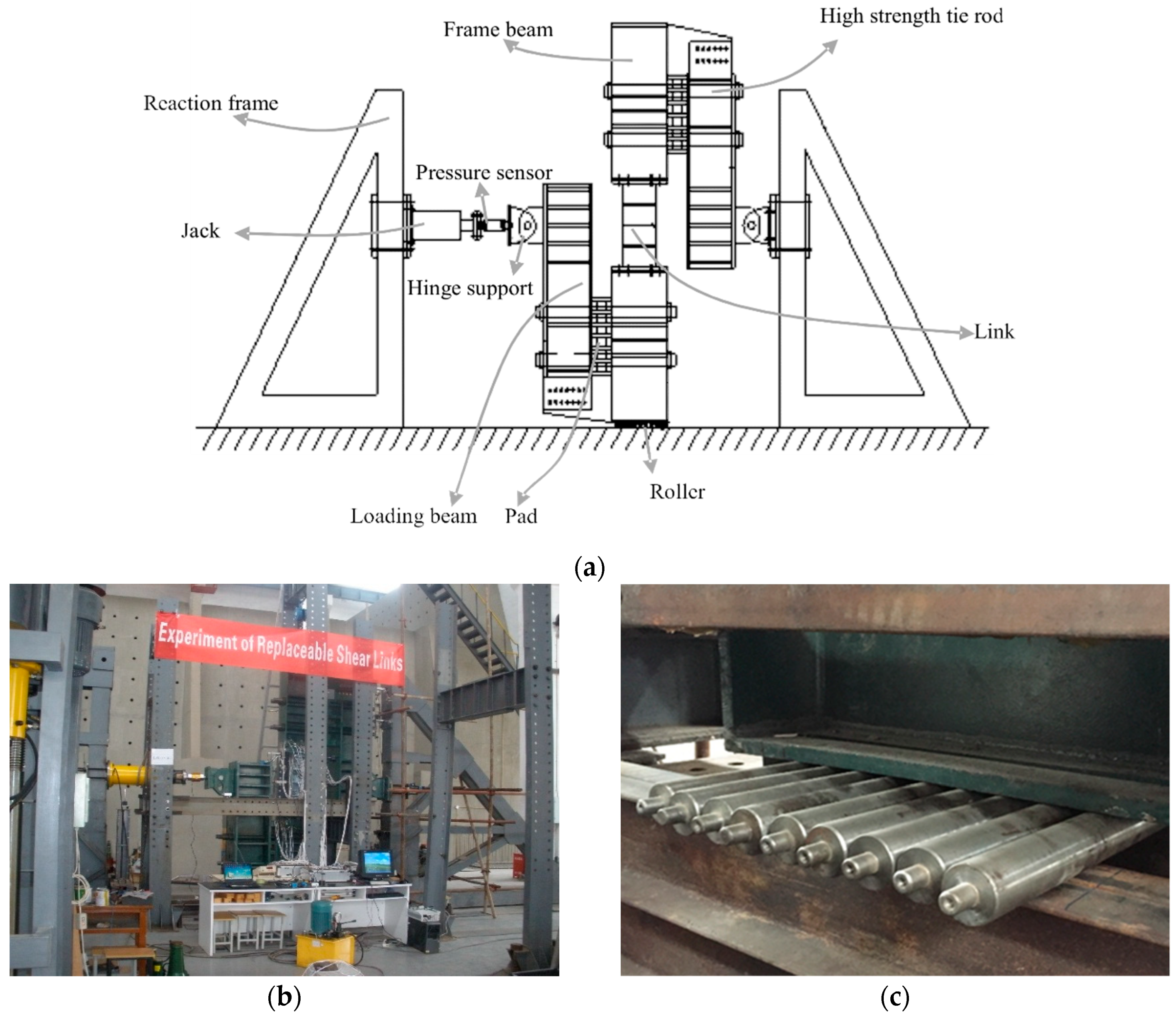
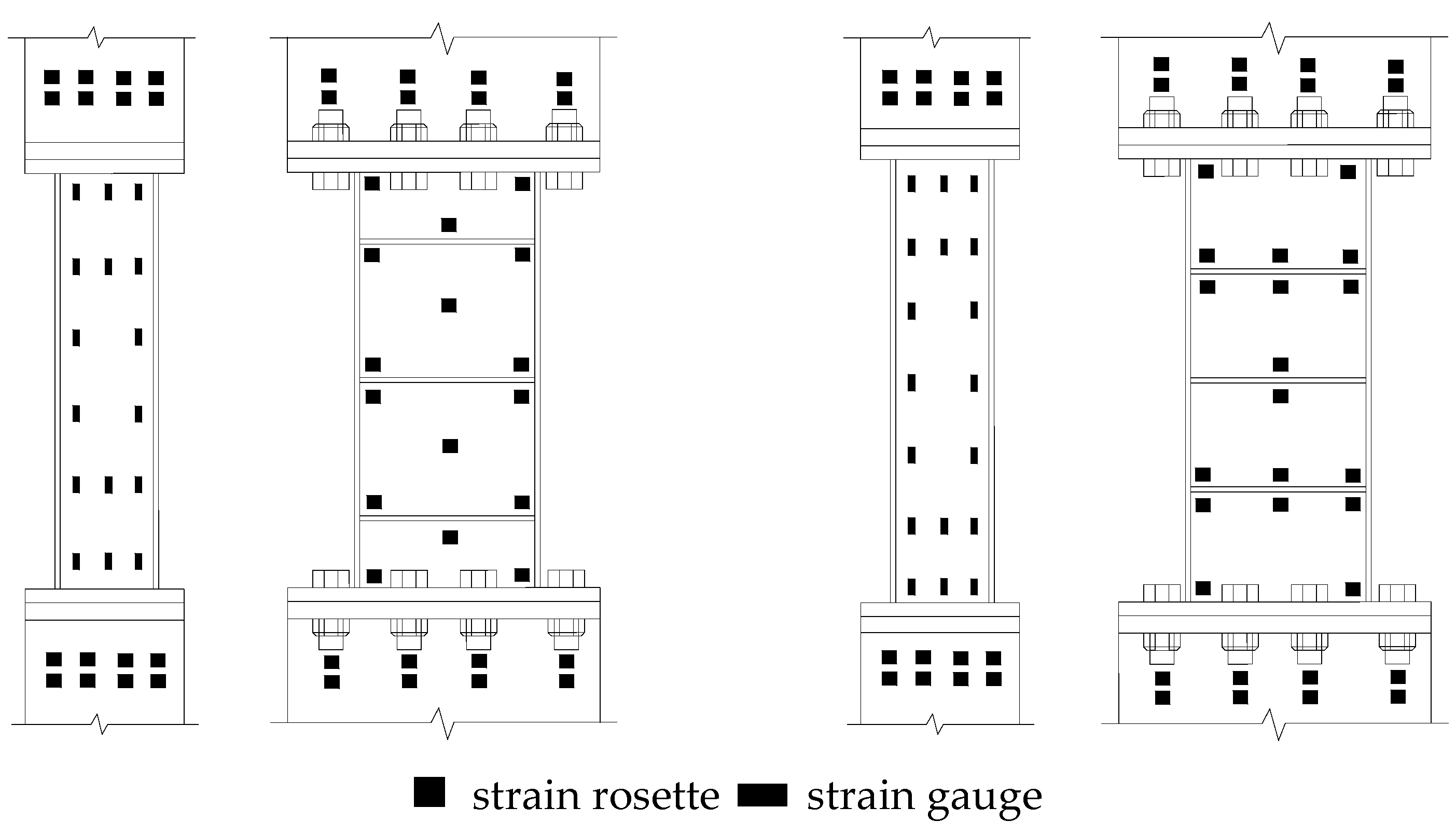
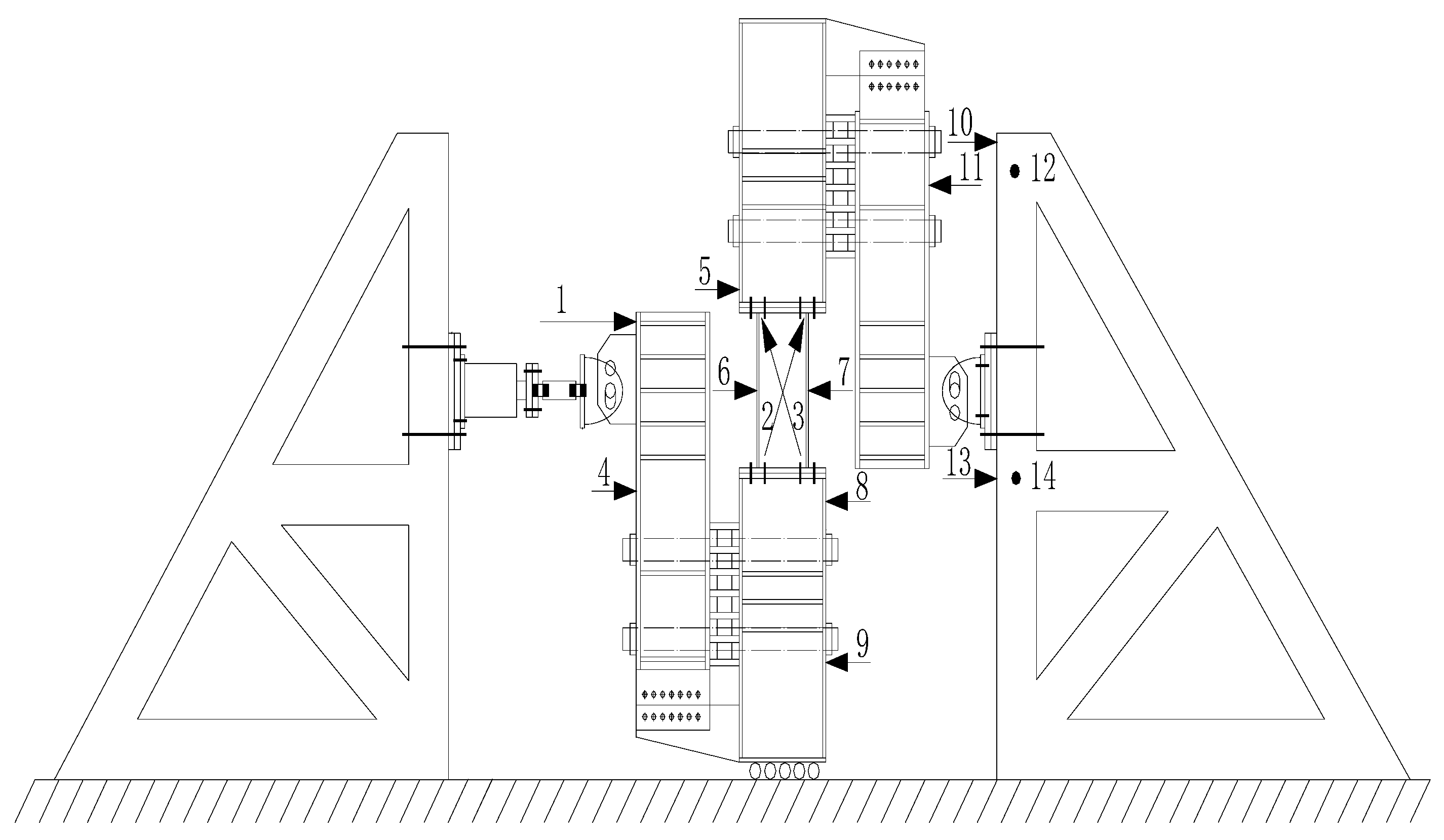
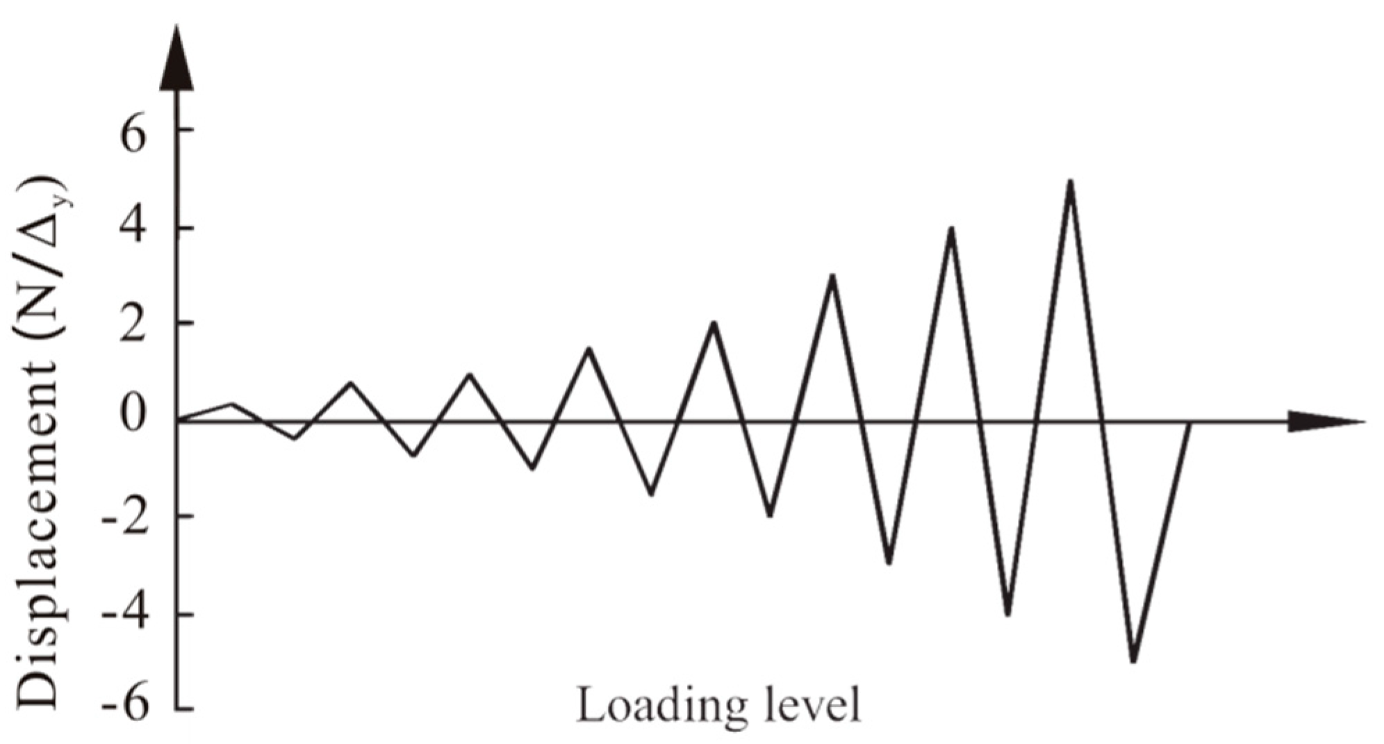
2.2. Test Setup, Instrumentation, and Loading Protocol

Figure 3a shows the test setup. The link specimen was securely clamped to two steel frame beams designed with large stiffness to simulate the constraint of adjacent frame beams to the link. A shear force was applied perpendicularly to the link to ensure both ends of the link were subjected to equal bending moments in opposite directions. The details of setup connection are as follows: the loading frames that measured 500 mm × 600 mm × 40 mm × 30 mm were arranged on one side of the frame beams measuring 500 mm × 300 mm × 12 mm × 30 mm, respectively. Besides the connections of the four high-strength tie rods between the loading beam and the frame beam, both their ends were connected to the end plates measuring 588 mm × 300 mm × 24 mm through a row of seven 10.9-class M26 high-strength bolts, and some box pads were placed between them. In addition, a load cell was pinned to the jack at one end and pinned to the left hinge support at the other hand. They were arranged between the left reaction frame and the left loading frame. The right hinge support was pinned to the right loading frame at one hand and was pinned to the right reaction frame at the other hand. The loading site is shown in Figure 3b. A row of rollers that could slide horizontally was added at the bottom of the lower frame beam to ensure the sliding of the bottom frame beam during the test (see Figure 3c). At the same time, the rollers were smeared with lubricant to reduce friction.
Instrumentation was used to measure the load, displacements, and strains of the specimen. The strain gauge and the strain rosette were mounted reasonably on the link and the frame beam by electric measurement to measure the strains of both links and beam segments (see Figure 4). In addition, the displacement was measured by a displacement meter. Figure 5 gives the arrangement of the displacement measuring points; among them, the points 1, 2, and 3 use pull-line displacement meters and the rest use resistance strain gauges. In this test, the DH3816 was used to collect the data from the strain gauge and the strain rosette. The tester could effectively control the loading process and use the system to collect the displacement on the pull-line displacement sensor through the DH5922N dynamic data acquisition system.
Figure 6 shows the cyclic loading pattern of the test. The displacement, Δ y , only considered applying a horizontal cyclic reciprocating load to the link, and adopted a displacement control loading method. It was loaded step by step according to the multiple of the yield displacement Δ y of the link in the constant-width loading system as follows: 0, Δ y , 0, − Δ y ; 0, 2 Δ y , 0, −2 Δ y ; 0, 3 Δ y , 0, −3 Δ y …, and the specimen was loaded until complete failure.

3. Experimental Results and Discussion

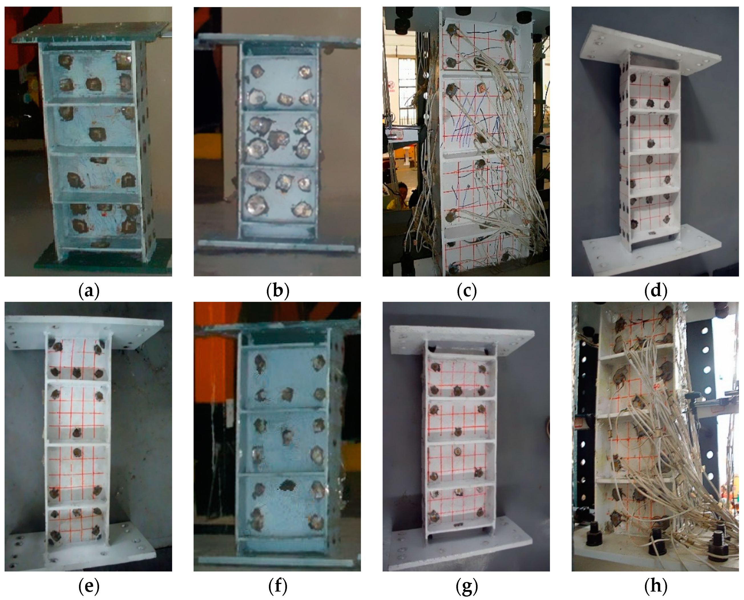
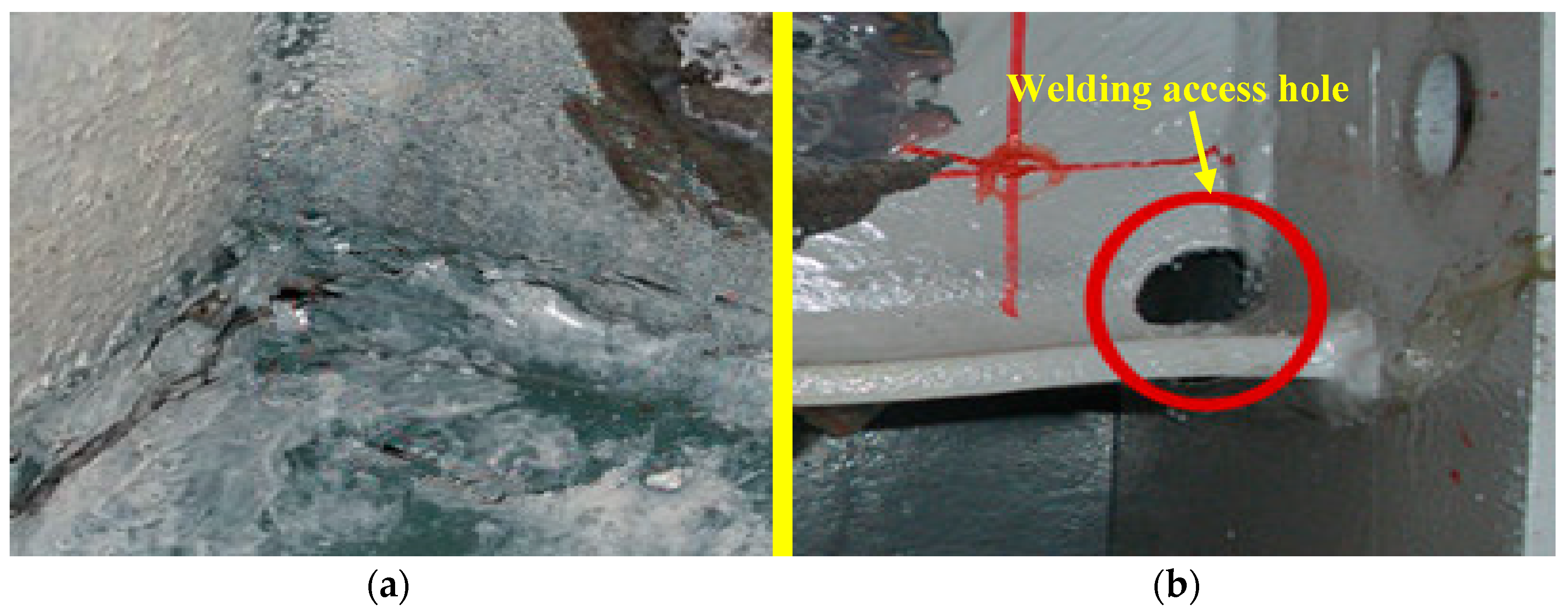
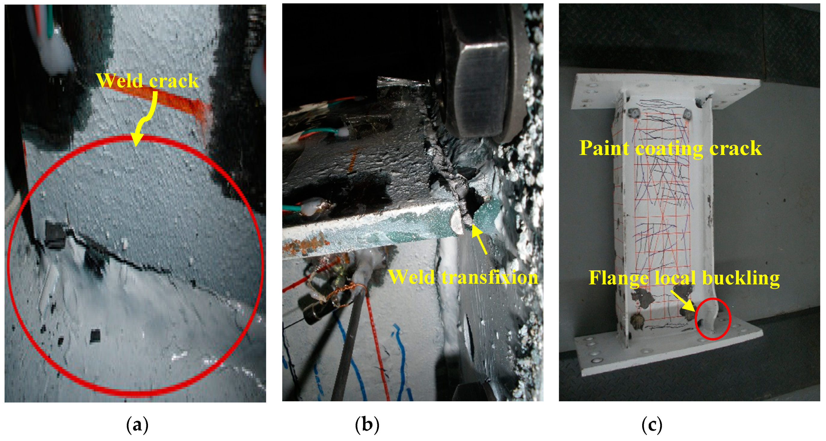
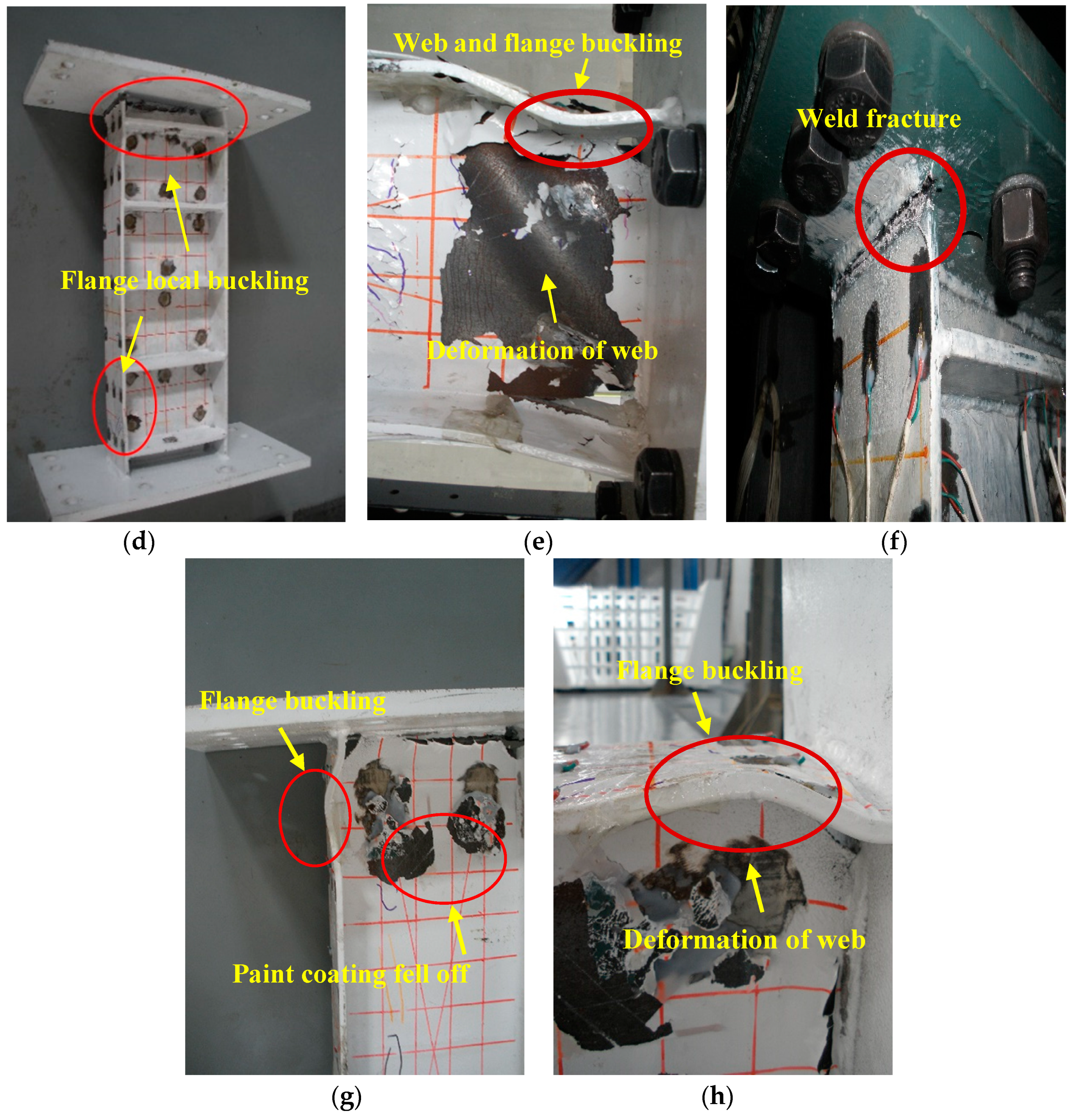
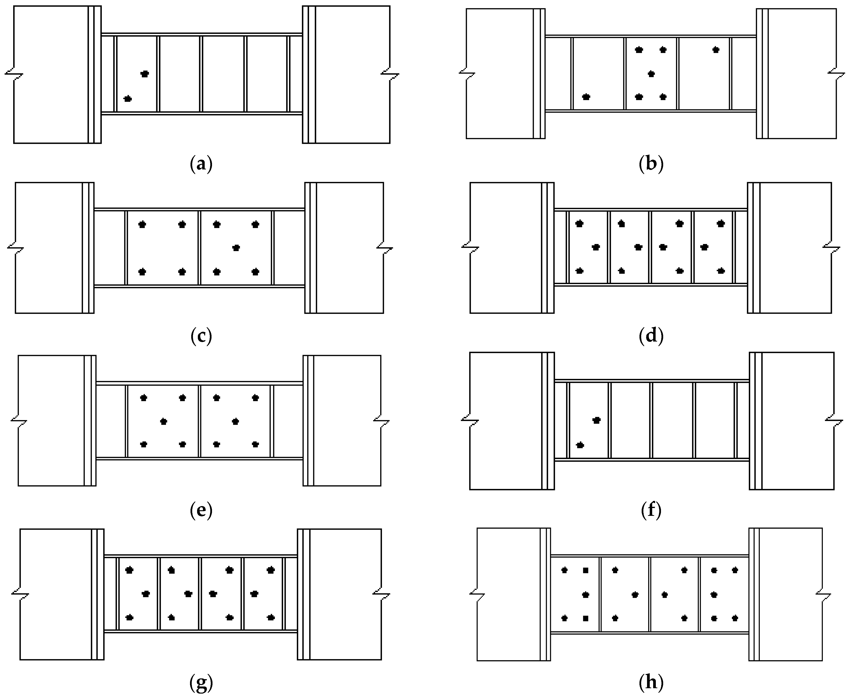
3.1. Damage Processes and Failure Mode

The results of the strain measurement indicated that the beam segments remained elastic during the test, and the damage occurred in the links only. Table 3 summarizes the process of visually identified damage and the cause of ultimate failure. In this study, the failure of the specimen was defined as the point where the shear strength dropped to below the link beam plastic strength V p . Paint coating bulging, web buckling, flange buckling, flange-to-end plate weld fracture, and failure mode were observed in the links. Figure 7 shows the specimens and provides a close look at the primary failure mode.
During the first to third cycles of test loading, all specimens were in elastic stage, and no obvious damage phenomenon was observed. There were three stages of cumulative damages of all specimens under the low-cycle cyclic loading. The first stage was the initial stage of damage process, which was characterized by the initiation of the specimens’ web yield. The yield of web spread from both ends of the link to the middle of the link increased with the loading displacement, where the web paint coating cracked or became slightly bulged. The duration of this stage was long, and cracks on the web paint coating developed continuously, which is considered to be the major stage of energy dissipation and damage accumulation. With the increase of loading displacement, the damage accumulated continually and then the process turned gradually into the second stable stage. In this stable stage, some micro-cracks appeared on the welds of Specimens L1, L2, and L6 (see Figure 7a). For other specimens, the paint coating bulged more obviously and partial paint coating tended to fall off (see Figure 7g). The surface darkening of the steel could be observed. Strain measurement indicated that the yield range slowly spread to the edge of the web. The link’s shape changed from rectangular to rhombic, and slight shear deformation of the web could be observed. The last stage is the failure stage. As shown in Figure 7b, the weld cracks of Specimens L1, L2, and L6 increased gradually and tended to transfixion. However, the welds at the end plate could not continue to bear the loading due to fracture or excessive cracks. The web and end plate of Specimens L3 and L4 dislocated relatively, and the flange of these specimens came up as slight local buckling (see Figure 7c). For Specimens L5, L7, and L8, the end of flange came up as large local buckling. As shown in Figure 7e, the webs of these specimens came up as some larger buckling, which failed by shear yield.
From the above-mentioned damage processes, eight specimens showed primarily three types of failure modes. The failure mode of Specimens L1, L2, and L6 was brittle failure of the link flange-to-end plate weld that cracked (see Figure 7f), which was mainly caused by the distribution of complex residual stress at the welds of the end plate due to the lack of a welding access hole. Specimens L3 and L4 failed by local buckling of the flange after shear yield of the web (see Figure 7d), which was likely caused by the energy dissipation of the link web yield coupled with the flexure yield of the flange. Specimens L5, L7, and L8 failed by shear yield of the web, which was mainly caused by the incessant interactive actions of the plastic development and deformation of the link web (see Figure 7h). In general, the failure modes of Specimens L3, L4, L5, L7, and L8 were considered to be ductile failure. As a result of the welding access hole adopted in the links, stress concentration at the weld was relieved.
From the above failure mode and damage process analyses, it was observed that cracks are the major causes of damage to the EBF specimens. However, the strain gauges used cannot monitor the damage to the EBF in real time and there is a lack of research on real-time monitoring of the onset and development of these cracks in EBF structures. As a future work, a planned new approach will be introduced in the later part of this section which employs piezoceramic patch transducers and active sensing to monitor the crack onset and development of the EBF subject to dynamic loadings.

3.2. Stress Distribution and Damage Analysis

The principal stress σ , the main strain ε , the shear stress τ , and the shear strain γ were calculated by treating the data of right-angle strained rosettes on the web according to the Formulas (2) and (3):
ε 1 ε 2 } = ε 0 ° + ε 9 0 ° 2 ± 1 2 ( ε 0 ° + ε 4 5 ° ) 2 + ( ε 4 5 ° + ε 9 0 ° ) 2 ,
γ xy = 2 ε 4 5 ° ε 0 ° ε 9 0 ° ,
where ε 0 ° , ε 4 5 ° , and ε 9 0 ° are, respectively, the strain in the horizontal, oblique, and vertical directions of the strain rosette, and μ is the Poisson ratio of material. Through the data processing of the stress and strain of each specimen, the measurement points of each specimen that came into plastic phase can be obtained.
Figure 8 gives the yielded points on the web of each specimen. For Specimens L1, L2, and L6 without a welding access hole, and because of the residual stress effects at the welds of the end plate, less than half of the measure points yielded, and only two of the measured points of Specimens L1 and L6 came into the plastic phase before brittle failure occurred. Specimens L3, L4, L5, L7, and L8 were less affected by the residual stress. Please note that L3 and L4 were damaged by flexure yield and L5, L7, and L8 were damaged by shear damage. The stress at the end of the flange is much larger than the yield stress of the material, and it is even close to or reaches the ultimate stress of the material for specimens of flexure damage. The shear stress on the web mostly exceeded the shear strength of the steel, and all the measured points yielded for specimens of shear yield. The yield area was large and the welds of the end plate had hardly any cracks. It is indicated that the stress level at the ends of the links decreased significantly using the welding access hole. Moreover, due to the welding access hole adopted in Specimens L3, L4, L5, L7, and L8, the stress distribution of the web was more uniform from the distribution of yielded points on the web of these specimens. At the same time, the connecting bolts between the link and the beam hardly slipped. However, the conclusion is contrary to Specimens L1, L2, and L6 without a welding access hole. The influence of the stiffener arrangement of the links on the stress distribution of the web was not obvious after shear yielding for Specimens L3, L4, L5, L7, and L8. As the link was damaged, both end plates connecting the link had no plastic deformation, and the high-strength bolts connecting links with beam did not show bending and shearing. In addition, the bolt hole walls were not damaged by the extrusion. At the same time, the stress on the frame beam did not exceed its yield stress, and the frame beam was still in the elastic phase. Combined with the stress state of the above eight specimens, the links could concentrate the plastic deformation into themselves.
In conclusion, link damage is caused by the incessant interactive actions of the plastic development and deformation, and it is possible to focus the structure’s inelasticity on the link.

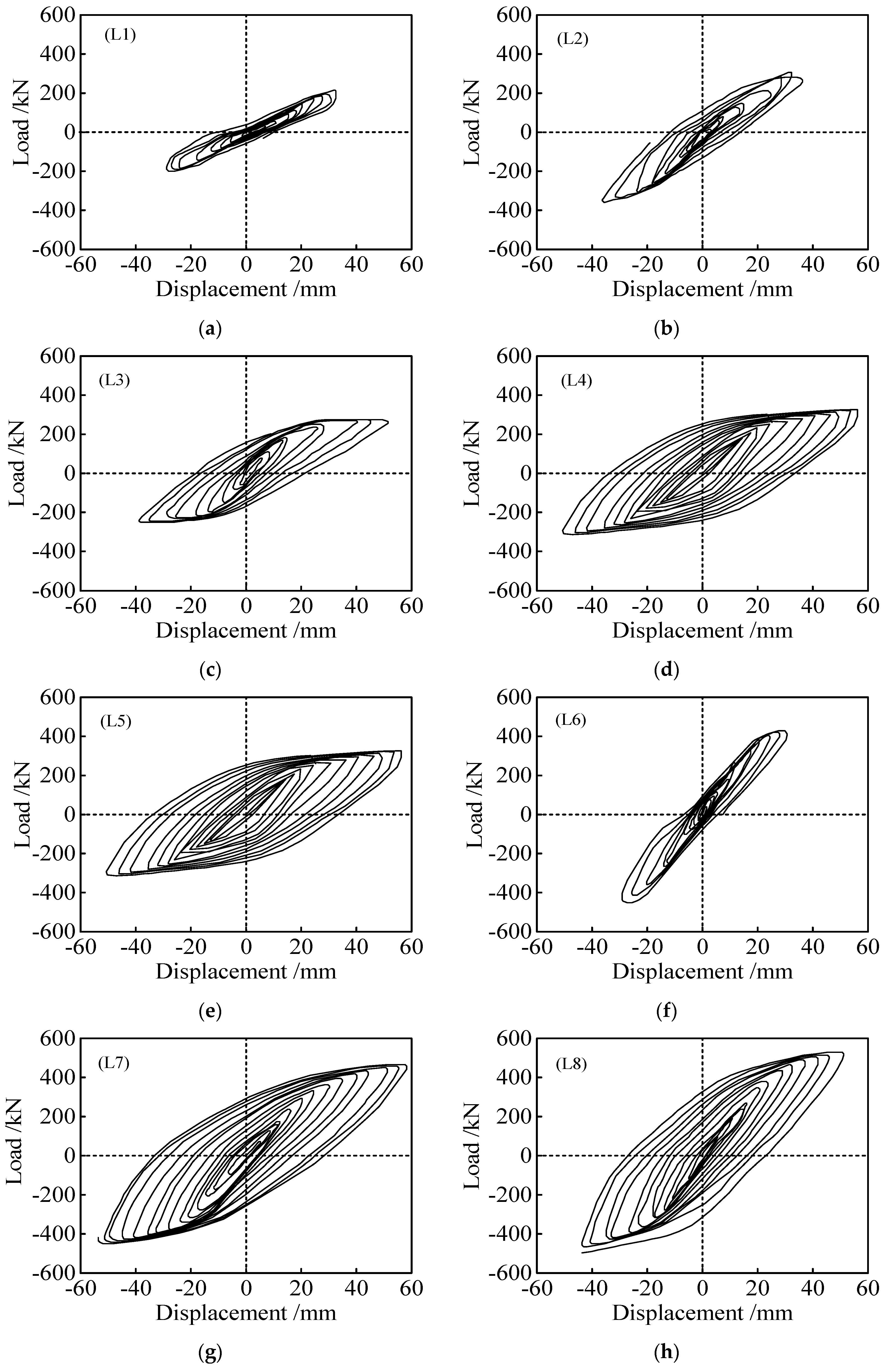
3.3. Hysteresis Curves

One of the important indicators to examine a structure’s seismic behavior is to analyze the deformation capacity and the energy dissipation capacity of the links using the hysteresis curve. Figure 9 shows the hysteresis responses of Specimens L1–L8 under the cycle loading. All specimens first went through the elastic stage, and then the link web began to yield. As a result, the plastic deformation of the structure gradually developed and the rigidity decreased as the loading cycles increased. Comparing the hysteresis curves of the specimens, the hysteresis loops of Specimens L1, L2, and L6 are quite different from those of the others, which were induced by the brittle failure of the link flange-to-end plate weld. The residual stress had a great influence on the link weld, non-ductile failure occurred on the welds, and the plasticity of the specimens was not fully developed. These specimens exhibited different levels of pinching in the hysteresis loops due to slippage of the high-strength bolts. On the contrary, Specimens L3, L4, L5, L7, and L8 with the welding access holes showed full and stable hysteresis loops with stable energy dissipation. It showed that the welding access holes of the link reduced the influence of residual stresses on the welds, and the energy dissipation behavior of the link was improved.

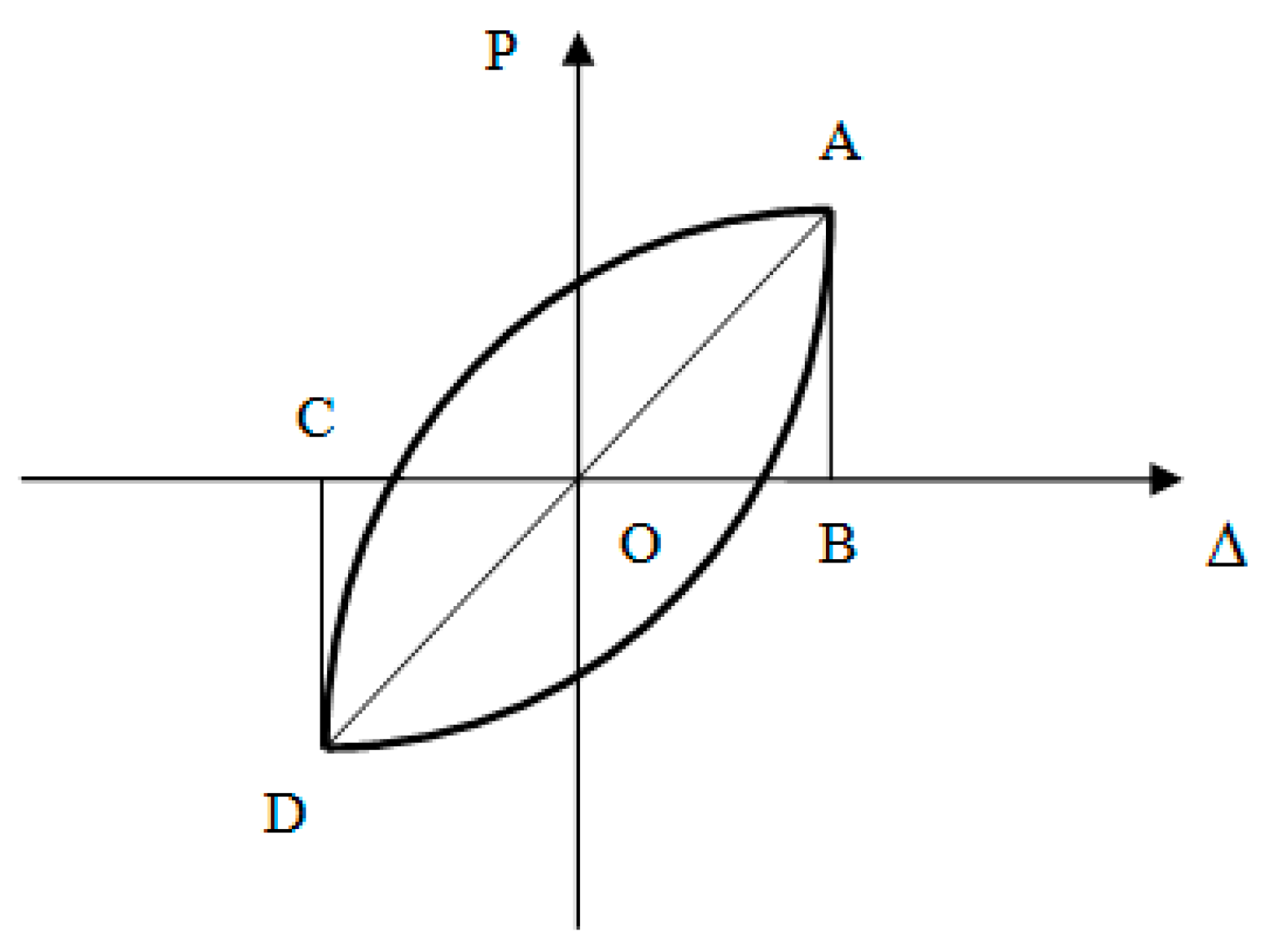
3.4. Energy Dissipation Behavior

The energy dissipation capacity of the structure can be reflected by the energy dissipation coefficient E and can be obtained by the calculation diagram for energy dissipation coefficient E, as shown in Figure 10.
With the help of Figure 10, E can be calculated according to the following equation:
E = S 1 S Δ A O B + Δ C O D ,
where S 1 is the area enclosed by the hysteresis loop of the specimen. Table 3 gives the dissipation coefficient of each specimen. It can be seen from the table that the dissipation coefficient of L3, L4, L5, L7, and L8 with welding access holes was between 1.59 and 1.98, which is higher than those without welding access holes such as Specimens L1, L2, and L6. This indicates that the welding access hole effectively improves the energy dissipation behavior of the link and relieves the stress concentration at the weld. From Table 4, the dissipation coefficient of L3 is 1.27% higher than that of L5, and L4 is 17.85% higher than that of L7 as the lengths of the specimens and the stiffener spacing are the same. The links with relatively smaller cross-sections control the energy dissipation behavior of the structure better, because the links ensure the force transmission on the same frame beam. Under the same length ratio, the dissipation coefficient of L4 is 24.53% higher than that of L3 and L7 is 7% higher than that of L5. The closer the stiffener arrangement of the link, the better the energy dissipation capacity; however, it should not be smaller than 0.5 times the depth of section of the links.

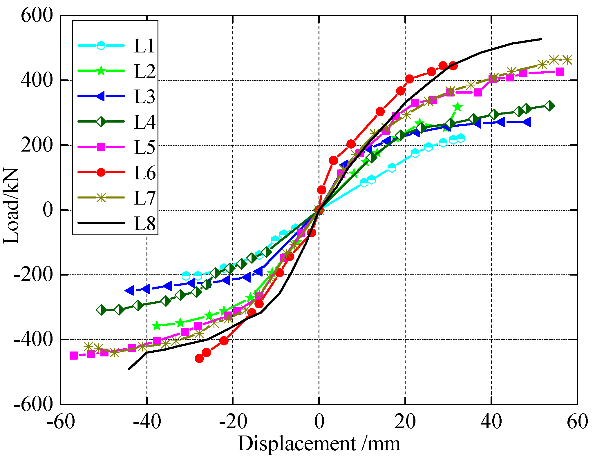
3.5. Skeleton Curves

The skeleton curves of all specimens are symmetrically distributed under tension and compression, which can better show the elastic stage, the strengthening stage, and the plastic stage of the specimen. The skeleton curves of Specimens L1, L2, and L6 have no plastic stage, as shown in Figure 11, which was induced by the brittle failure of the link flange-to-end plate weld and because the plasticity of the specimens was not fully developed. In contrast, the skeleton curves of Specimens L3, L4, L5, L7, and L8 with welding access holes are more distinct in each stage. Table 5 summarizes the initial stiffness, the yield bearing capacity F y , the maximum bearing capacity F u , the yield displacement Δ y , the ultimate displacement Δ u , and the plastic rotation angle γ p of the specimens. The bearing capacity of L8 was larger than that of L5 and L7, and the bearing capacity of L5 and L7 were larger than that of L3 and L4. It was explained that the length ratio ζ was smaller and the bearing capacity was larger. In addition, the stiffener spacing for Specimens L3 and L4 was 200 mm and 150 mm, respectively, and the peak load difference between them was 13.6%. The stiffener spacing for Specimens L5 and L7 was 200 mm and 150 mm, respectively, and the peak load difference between them was 9.2%. Nevertheless, the yield loads of Specimens L3 and L4 are approximately the same, as are those of Specimens L5 and L7. It is shown that stiffener spacing has a greater influence on the peak load than on the yield load. This occurs because of the comparatively close stiffener arrangement of the specimen, and the buckling of the web can be limited as the peak load is increased. The bearing capacities of L1 and L2 were less than those of L3 and L4, and the bearing capacity of L6 was less than that of LB5, LB7, and LB8, respectively, which shows that the welding access hole is conducive to delaying the damage of specimens.
The initial stiffness of Specimens L1, L2, and L6 was not considered because of the brittle failure in the elastic stage. According to the skeleton curve, the other specimens underwent the elastic stage and the linear strengthening stage. The initial stiffness of L8 was larger than that of L5, L7, L3, and L4, which shows that the smaller the length ratio ζ, the larger the initial stiffness. The skeleton curve trends of both L3 and L4 are the same, as were those of L5 and L7. It is clear that the stiffener spacing has little effect on the initial stiffness.

3.6. Plastic Rotation Angle

The inelastic rotation angle, γ p , is evaluated by removing the contributions of elastic response from the link rotation angle. While the link rotation included components attributed to the elastic deformation of the vertical link and frame beam, those components were removed to obtain the inelastic rotation angle. Table 5 shows that the plastic rotation angles of all the specimens are between 0.08 and 0.16 except for Specimen L1, which satisfies the limit requirement of AISC 341-10 for the plastic rotation angles of link beams of eccentrically braced steel frames exceeding 0.08rad. It indicates that the length ratio is the main factor affecting the plastic rotation angles. The plastic rotation angles of L1, L2, and L6 are smaller than those of other specimens. The welding access hole reduces the influence of residual stress at the welds, which avoids the stress concentration and makes the links have a better plastic deformation ability. The plastic angle of L4 is 50% larger than that of L3 and the plastic angle of L7 is 14% larger than that of L5 under a different stiffener arrangement, which indicates that the link with smaller stiffener spacing has a better shear deformation capacity. In summary, the length ratio, welding access holes, and stiffener spacing are the important factors affecting the plastic deformation capacity of links.

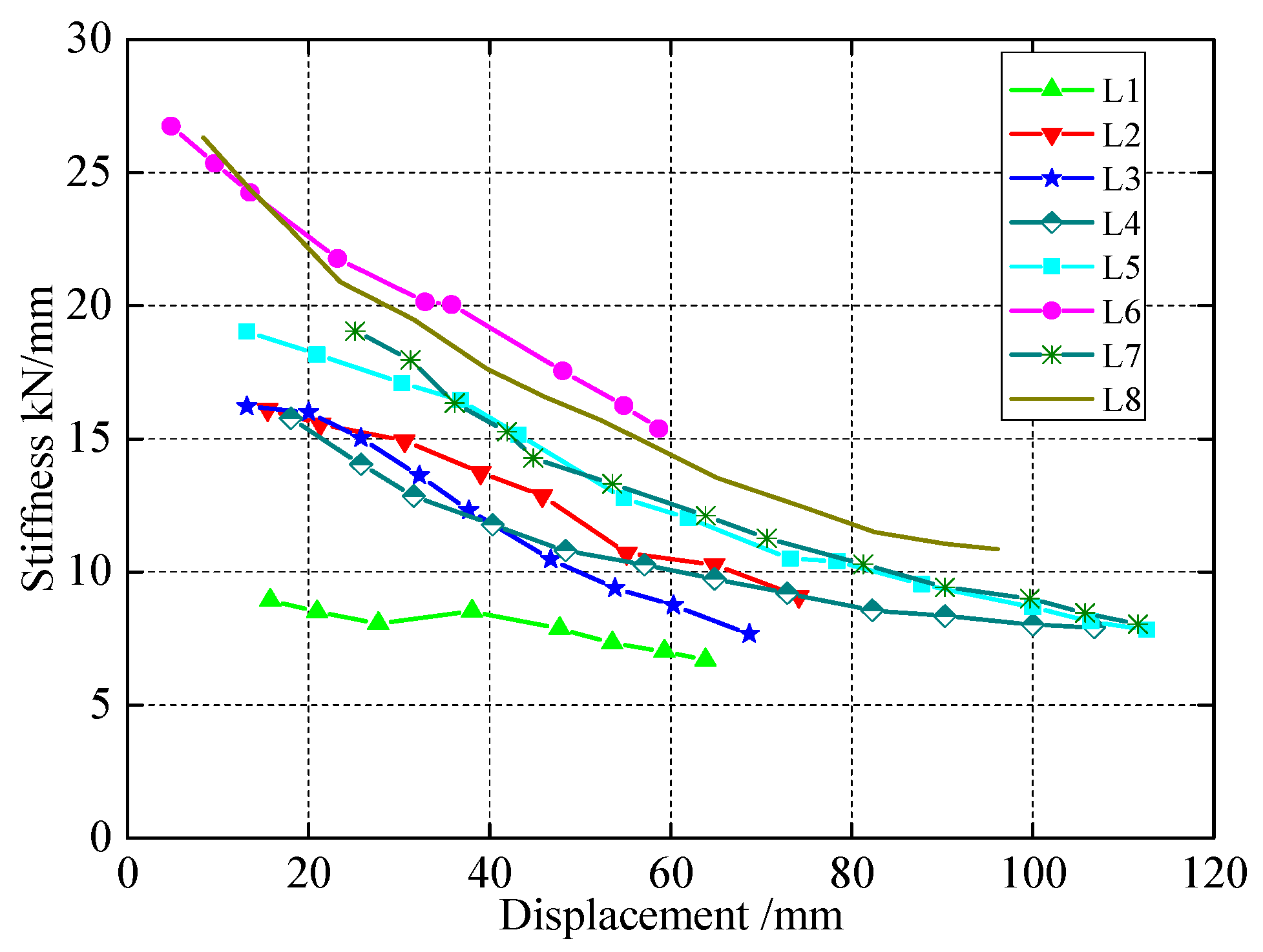
3.7. Stiffness Degradation

Stiffness degradation represents the tendency of the structure’s stiffness to gradually decrease as the loading cycles increase, which can fully reflect the development of plastic deformation of the links. The stiffness of a specimen was commonly evaluated in accordance with the following formula:
K i = | P i + | + | P i | | Δ i + | + | Δ i | ,
where, K i is the stiffness at i loading cycle, P i + and P i are, respectively, the maximum load at the positive and negative directions at i loading cycle, and Δ i + and Δ i are, respectively, the maximum displacement at both the positive and negative directions at i loading cycle. The secant stiffness method was used to get the stiffness degradation curve of each specimen, as shown in Figure 12. There was a slight decrease in stiffness with an increase in displacement. The stiffness degradation ranges of Specimens L1 through L8 are 25.6%, 43.5%, 52.5%, 50.3%, 58.9%, 59.5%, 43.1%, and 58.1%, respectively. The stiffness degradation amplitude of Specimen L3 is larger than that of Specimen L4, which shows that the earlier the specimen yields, the more obvious the stiffness degradation will be. The stiffness degradation rate of Specimen L4 is 50.3%, which is less than 58.1% of Specimen L7, and the degradation rate of Specimen L3 is 52.5%, which is less than 58.9% of Specimen L5. It explains that stiffness degradation is obvious with the decrease of length ratio ζ. The stiffness degradation ranges of Specimens L5 and L7 are basically the same, which shows that the stiffener spacing has little effect on the stiffness degradation.

3.8. Discussion on Real-Time Damage Monitoring

It is clear from the above analyses that cracks and bolt failures were observed during the tests. From this research, we see the urgent need for crack monitoring and bolt loosening monitoring after a seismic event. However, the strain gauge sensors used cannot monitor these types of damages in real time. During recent years, emphasis has been placed on structural health monitoring (SHM) [47,48] in civil engineering [49,50,51]. An SHM system has the ability to monitor the health status of a structure in real time based on integrated sensors and to issue early warnings based on advanced algorithms to prevent catastrophic consequences [52,53,54]. A commonly used type of sensor in SHM is the PZT (lead zirconate titanate) [55,56,57,58], a type of piezoceramic material with a strong piezoelectric effect. Enabled by the piezoelectric effect, a PZT transducer can be used as an actuator [59,60] or as a sensor [61,62]. PZT transducers have other advantages, such as wide bandwidth [63,64,65,66], fast response, and low cost. Therefore, PZT transducers are often be used to generate and detect stress waves in an SHM system [67,68,69,70].
As we continue future work, we plan to use PZT patch transducers, which can be easily bonded onto the outer surface of structures, to monitor the onset and development of cracks. From this study, we know the approximate locations for potential cracks. Two PZT patches will be strategically placed across the potential location. The so-called active sensing method [71,72,73,74] will be adopted to monitor the cracks. In the active sensing approach, one PZT patch will be used to generate a stress wave that can propagate along a structure, and another PZT patch can also be used as a sensor to detect the stress wave. If a crack, which functions as a stress relieve [75,76], is formed, the energy of the stress wave that travels across the crack will be greatly reduced, based on which the onset and development of the crack on the structure can be monitored in real time. Using the active sensing approach, bolt loosening can be detected by surface-bonded PZT on the bolt head and on the structure since a bolt loosening event will significantly alter the stress wave propagating between the two PZT patches. In our future tests, we will explore the use of PZT patches to quickly evaluate structural integrity by detecting cracks and bolt loosening after a seismic event.

4. Conclusions

Cyclic quasi-static tests were performed on eight replaceable links with different parameters in EBF. The seismic behavior and damage modes of specimens were analyzed. As the replaceable links are separated from the frame beams, inelastic deformation is concentrated in the shear link during a severe earthquake; therefore, damaged links can be easily replaced. Based on the results, the following conclusions were drawn:
(1)
The failure mode of specimens without welding access holes was brittle failure of the link flange-to-end plate weld that cracked, which was caused by the distribution of complex residual stress at the welds of the end plate. Owing to the welding access hole adopted in links, stress distribution of the web was more uniform, and the failure modes of specimens were ductile failure.
(2)
Stress distribution of the web was more uniform for links with the welding access hole than for links without the welding access hole, and the effect of the stiffener of specimens after shear yielding was not obvious. Link damage is caused by the incessant interactive actions of the plastic development and deformation, and it is possible to focus the structure’s inelasticity on the link.
(3)
The hysteresis curves of the replaceable links with welding access holes were stable and the inelastic deformation of the structure could be concentrated in the links. The link was treated using welding access holes that had a prominent effect on the improvement of seismic behavior.
(4)
The energy dissipation capacity of the specimen was mainly dependent on the arrangement of stiffeners and the welding access holes. When the dimensions and lengths of the specimens were the same, the energy dissipation capacity of the specimen with relatively closer stiffener spacing was better. The energy dissipation capacity of the specimen with welding access holes was better than that of specimens without welding access holes, where welding access holes relieved stress distribution.
(5)
Welding access holes effectively enhanced the plastic deformation capacity of the links, where the minimum plastic rotation angle of the specimen was 0.10rad and the maximum was 0.16rad. As the section dimension and length of the link were the same, the stiffener spacing had the same remarkable effect on the plastic deformation capacity of the link.
(6)
The stiffener spacing, the welding access holes, and the length ratio ζ had a remarkable effect on the bearing capacity of the links. The bearing capacity of the specimen with welding access holes was better than the other specimens. The smaller the length ratio ζ, the larger the bearing capacity would be. The length ratio ζ had a great influence on the initial stiffness of the link.
(7)
The stiffness degradation of the link was mainly dependent on the length ratio ζ. As the length and the stiffener spacing were the same, the smaller the length ratio ζ of the specimen, the more obvious the stiffness degradation.
(8)
In our future work, we will explore the use of PZT patches and the active sensing method to quickly evaluate structural integrity by detecting cracks and bolt loosening after a seismic event.

Author Contributions

Z.Y. designed the experiments. D.F. performed the experiments. Z.Y., D.F., and W.Y. analyzed the data and wrote the paper.

Funding

This research was supported in part by the National NSFC (Natural Science Foundation of China) (51368037, 51568040), the Basic Research Foundation of Colleges, and the Universities of Gansu Province.

Acknowledgments

The research presented in this paper is part of Project (51368037, 51568040) supported by National Natural Science Foundation of China. In addition, authors would like to acknowledge the support from Lanzhou University of Technology in China experimental equipment for this research and Ningxia University for providing technical consultation.

Conflicts of Interest

The authors declare no conflict of interest.

References

  1. Fujimoto, M.; Aoyagi, T.; Ukai, K.; Wada, A.; Saito, K. Structural characteristics of eccentric k-braced frames. Trans. Archit. Inst. Jpn. 1972, 195, 39–49. [Google Scholar] [CrossRef]
  2. Tanabashi, R.; Naneta, K.; Ishida, T. On the rigidity and ductility of steel bracing assemblage. In Proceedings of the 5th World Conference on Earthquake Engineering, Rome, Italy, 25–29 June 1973; IAEE: Rome, Italy, 1974; pp. 834–840. [Google Scholar]
  3. Roeder, C.W.; Popov, E.P. Inelastic behavior of eccentrically braced steel frames under cyclic loadings. Akusherstvo I Ginekologiia 1953, 2, 67–69. [Google Scholar]
  4. Teal, R. Practical Design of Eccentric Braced Frames to Resist Seismic Forces; Structural Steel Research Council: Lafayette, CA, USA, 1979. [Google Scholar]
  5. Libby, J.R. Eccentrically braced frame construction—A case study. Eng. J. 1981, 18, 149–153. [Google Scholar]
  6. Merovich, A.T.; Nicoletti, J.P.; Hartle, E. Eccentric bracing in tall buildings. ASCE J. Struct. Div. 1982, 108, 3059–3075. [Google Scholar]
  7. Miller, D.K. Lessons learned from the Northridge earthquake. Eng. Struct. 1998, 20, 249–260. [Google Scholar] [CrossRef]
  8. Krawinkler, H. Shear in beam–column joints in seismic design of steel frames. AISC Eng. J. 1978, 3, 82–91. [Google Scholar]
  9. Popov, E.P. Panel zone flexibility in seismic moment joints. J. Constr. Steel Res. 1987, 8, 91–118. [Google Scholar] [CrossRef]
  10. Naeim, F. The Seismic Design Handbook; Van Nostrand Reinhold: New York, NY, USA, 1989. [Google Scholar]
  11. Maleki, S.; Tabbakhha, M. Numerical study of Slotted-Web–Reduced-Flange moment connection. J. Constr. Steel Res. 2012, 69, 1–7. [Google Scholar] [CrossRef]
  12. Rao, D.V.; Kumar, S.R. RHS beam-to-column connection with web opening—Parametric study and design guidelines. J. Constr. Steel Res. 2006, 62, 747–756. [Google Scholar]
  13. Malley, J.O.; Popov, E.P. Shear links in eccentrically braced frames. J. Struct. Eng. 1984, 110, 2275–2295. [Google Scholar] [CrossRef]
  14. Kasai, K.; Popov, E.P. Cyclic web buckling control for shear link beams. ASCE J. Struct. Eng. 1986, 112, 505–523. [Google Scholar] [CrossRef]
  15. Hamed, K.; Ghanbari, G.T.; Mohammad, H. Numerical study on steel shear walls with sinusoidal corrugated plates. Lat. Am. J. Solids Struct. 2016, 13, 2802–2814. [Google Scholar]
  16. Kazuhiko, K.; Popov, E.P. General behavior of WF steel shear link beams. J. Struct. Eng. 1986, 112, 362–382. [Google Scholar]
  17. Popov, E.P.; Engelhardt, M.D. Seismic eccentrically braced frames. J. Constr. Steel Res. 2010, 2, 53–74. [Google Scholar] [CrossRef]
  18. Okazaki, T.; Arce, G.; Ryu, H.C. Experimental study of local buckling, over strength, and fracture of links in eccentrically braced frames. J. Struct. Eng. 2005, 131, 1526–1535. [Google Scholar] [CrossRef]
  19. Lv, X.L.; Chen, Y.; Jiang, H.J. Experimental study on seismic behavior of “Fuse” of replaceable coupling beam. J. Tongji Univ. 2013, 41, 1318–1325, 1332. [Google Scholar]
  20. Ji, X.D.; Wang, Y.D.; Ma, Q.F.; Qian, J.R. Cyclic behavior of replaceable steel coupling beams. J. Struct. Eng. 2016, 104, 1–8. [Google Scholar]
  21. Yin, Z.Z.; Ren, Y.G.; Chen, W.; Liang, Y.X. The seismic performance analysis of replaceable independent links. J. Eng. Mech. 2016, 33, 207–213. [Google Scholar]
  22. Popov, E.P. Recent research on eccentrically braced frames. Eng. Struct. J. 1983, 5, 3–9. [Google Scholar] [CrossRef]
  23. Hjelmstad, K.D.; Popov, E.P. Cyclic behavior and design of link beams. J. Struct. Eng. 1983, 109, 2387–2403. [Google Scholar] [CrossRef]
  24. Popov, E.P.; Tsai, K.C.; Engelhard, M.D. Advances in design of eccentrically braced frames. J. Earthq. Spectra 1987, 3, 43–55. [Google Scholar] [CrossRef]
  25. Okazaki, T.; Engelhardt, M.D. Cyclic loading behavior of EBF links constructed of ASTM A992 steel. J. Constr. Steel Res. 2007, 63, 751–765. [Google Scholar] [CrossRef]
  26. Bouwkamp, J.; Vetr, M.G.; Ghamari, A. An analytical model for inelastic cyclic response of eccentrically braced frame with vertical shear link (v-ebf). Case Stud. Struct. Eng. 2016, 6, 31–44. [Google Scholar] [CrossRef]
  27. Ricles, J.M.; Popov, E.P. Composite action in eccentrically braced frames. J. Struct. Eng. 1989, 115, 2046–2066. [Google Scholar] [CrossRef]
  28. Ricles, J.M.; Popov, E.P. Inelastic Link Element for EBF Seismic Analysis. J. Struct. Eng. 1994, 120, 441–463. [Google Scholar]
  29. Uang, C.M.; Seible, F.; McDaniel, C.; Chou, C.C. Performance evaluation of shear links and orthotropic bridge deck panels for the new san francisco–oakland bay bridge. Earthq. Eng. Struct. Dyn. 2010, 34, 393–408. [Google Scholar] [CrossRef]
  30. Okazaki, T.; Engelhardt, M.D.; Drolias, A.; Schell, E.; Hong, J.K.; Uang, C.M. Experimental investigation of link-to-column connections in eccentrically braced frames. J. Constr. Steel Res. 2009, 65, 1401–1412. [Google Scholar] [CrossRef]
  31. Wang, B.S.; Sherif, E. Experimental and analytical investigation of tubular links for eccentrically braced frames. Eng. Struct. 2007, 29, 1929–1938. [Google Scholar]
  32. Lian, M.; Su, M. Seismic performance of high-strength steel fabricated eccentrically braced frame with vertical shear link. J. Constr. Steel Res. 2017, 137, 262–285. [Google Scholar] [CrossRef]
  33. Gates, W.E.; Morden, M. Professional structural engineering experience related to welded steel moment frames following the Northridge earthquake. Struct. Des. Tall Build. 1996, 5, 29–44. [Google Scholar] [CrossRef]
  34. Sabol, P. Seismic-resistant steel moment connections: Developments since the 1994 northridge earthquake. Prog. Struc. Eng. Mater. 2010, 1, 68–77. [Google Scholar]
  35. Xu, W.F.; Yang, X.; Wang, F.L.; Chi, B. Experimental and numerical study on the seismic performance of prefabricated reinforced masonry shear walls. Appl. Sci. 2018, 8, 1856. [Google Scholar] [CrossRef]
  36. Yang, W.W.; Bao, C.; Ma, X.T.; Zhang, S.R. Study on structural robustness of isolated structure based on seismic response. Appl. Sci. 2018, 8, 1686. [Google Scholar] [CrossRef]
  37. Mansour, N.; Christopoulos, C.; Tremblay, R. Experimental validation of replaceable shear links for eccentrically braced steel frames. J. Struct. Eng. 2011, 137, 1141–1152. [Google Scholar] [CrossRef]
  38. Showkati, H.; Ghazijahani, T.G.; Noori, A. Experiments on elastically braced castellated beams. J. Constr. Steel Res. 2012, 77, 163–172. [Google Scholar] [CrossRef]
  39. Kulak, G.L.; Green, D.L. Design of connectors in web-flange beam or girder splices. Eng. J. 1990, 27, 41–48. [Google Scholar]
  40. Suo, Y.Q.; Yang, W.W.; Chen, P. Study on hysteresis model of welding material in unstiffened welded joints of steel tubular truss structure. Appl. Sci. 2018, 8, 1701. [Google Scholar] [CrossRef]
  41. American Institute of Steel Construction. Steel Construction Manual, 13th ed.; AISC 325-05; American Institute of Steel Construction Inc.: Chicago, IL, USA, 2005. [Google Scholar]
  42. American Institute of Steel Construction. Seismic Provisions for Structural Steel Buildings; AISC 341-10; American Institute of Steel Construction Inc.: Chicago, IL, USA, 2005. [Google Scholar]
  43. Wang, T.; Song, G.; Liu, S.; Li, Y.; Xiao, H. Review of bolted connection monitoring. Int. J. Distrib. Sens. Netw. 2013, 9, 871213. [Google Scholar] [CrossRef]
  44. Kulak, G.L.; Fisher, J.W.; Struik, J.H.A. Guide to Design Criteria for Bolted and Riveted Joints, 2nd ed.; Wiley: New York, NY, USA, 1987. [Google Scholar]
  45. American Institute of Steel Construction. Specification for Structural Steel Buildings; AISC 360-10; American Institute of Steel Construction Inc.: Chicago, IL, USA, 2005. [Google Scholar]
  46. Chinese National Standard. Design of Steel Structures; GB 50017-2003; China Ministry of Construction: Beijing, China, 2003. [Google Scholar]
  47. Balageas, D.; Fritzen, C.P.; Güemes, A. Structural Health Monitoring; John Wiley & Sons: Hoboken, NJ, USA, 2010. [Google Scholar]
  48. Song, G.; Wang, C.; Wang, B. Structural health monitoring (SHM) of civil structures. Appl. Sci. 2017, 7, 789. [Google Scholar] [CrossRef]
  49. Sun, M.; Staszewski, W.J.; Swamy, R.N. Smart sensing technologies for structural health monitoring of civil engineering structures. Adv. Civ. Eng. 2010, 2010, 724962. [Google Scholar] [CrossRef]
  50. Li, D.; Ho, S.C.M.; Song, G.; Ren, L.; Li, H. A review of damage detection methods for wind turbine blades. Smart Mater. Struct. 2015, 24, 033001. [Google Scholar] [CrossRef]
  51. Brownjohn, J. Structural health monitoring of civil infrastructure. Philos. Trans. R. Soc. A Math. Phys. Eng. Sci. 2007, 365, 589–622. [Google Scholar] [CrossRef] [PubMed] [Green Version]
  52. Lehmhus, D.; Busse, M. Structural health monitoring (SHM). In Material-Integrated Intelligent Systems: Technology and Applications; Wiley: New York, NY, USA, 2018; pp. 529–570. [Google Scholar]
  53. Du, G.; Kong, Q.; Zhou, H.; Gu, H. Multiple cracks detection in pipeline using damage index matrix based on piezoceramic transducer-enabled stress wave propagation. Sensors 2017, 17, 1812. [Google Scholar] [CrossRef] [PubMed]
  54. Kong, Q.; Robert, R.H.; Silva, P.; Mo, Y.L. Cyclic crack monitoring of a reinforced concrete column under simulated pseudo-dynamic loading using piezoceramic-based smart aggregates. Appl. Sci. 2016, 6, 341. [Google Scholar] [CrossRef]
  55. Xu, J.; Wang, C.; Li, H.; Zhang, C.; Hao, J.; Fan, S. Health Monitoring of Bolted Spherical Joint Connection Based on Active Sensing Technique Using Piezoceramic Transducers. Sensors 2018, 18, 1727. [Google Scholar] [CrossRef] [PubMed]
  56. Feng, Q.; Kong, Q.; Huo, L.; Song, G. Crack detection and leakage monitoring on reinforced concrete pipe. Smart Mater. Struct. 2015, 24, 115020. [Google Scholar] [CrossRef]
  57. Qin, F.; Kong, Q.; Li, M.; Mo, Y.L.; Song, G.; Fan, F. Bond slip detection of steel plate and concrete beams using smart aggregates. Smart Mater. Struct. 2015, 24, 115039. [Google Scholar] [CrossRef]
  58. Yang, Y.; Divsholi, B.S.; Soh, C.K. A reusable PZT transducer for monitoring initial hydration and structural health of concrete. Sensors 2010, 10, 5193–5208. [Google Scholar] [CrossRef]
  59. Agrawal, B.N.; Elshafei, M.A.; Song, G. Adaptive antenna shape control using piezoelectric actuators. Acta Astronaut. 1997, 40, 821–826. [Google Scholar] [CrossRef]
  60. Song, G.; Qiao, P.; Sethi, V.; Prasad, A. Active vibration control of a smart pultruded fiber-reinforced polymer I-beam. Smart Mater. Struct. 2004, 13, 819. [Google Scholar] [CrossRef]
  61. Sethi, V.; Song, G. Multimodal vibration control of a flexible structure using piezoceramic sensor and actuator. J. Int. Mater. Syst. Struct. 2008, 19, 573–582. [Google Scholar] [CrossRef]
  62. Park, J.M.; Kong, J.W.; Kim, D.S.; Yoon, D.J. Nondestructive damage detection and interfacial evaluation of single-fibers/epoxy composites using PZT, PVDF and P (VDF-TrFE) copolymer sensors. Compos. Sci. Technol. 2005, 65, 241–256. [Google Scholar] [CrossRef]
  63. Hirsch, S.; Doerner, S.; Schimpf, S.; Lucklum, R.; Hauptmann, P.; Schmidt, B. A new device with PZT ultrasonic transducers in MEMS technology. J. Phys. Conf. Ser. 2006, 34, 475. [Google Scholar] [CrossRef]
  64. Siu, S.; Ji, Q.; Wu, W. Stress wave communication in concrete: I. Characterization of a smart aggregate based concrete channel. Smart Mater. Struct. 2014, 23, 125030. [Google Scholar] [CrossRef]
  65. Ji, Q.; Ho, M.; Zheng, R.; Ding, Z. An exploratory study of stress wave communication in concrete structures. Smart Struct. Syst. 2015, 15, 135–150. [Google Scholar] [CrossRef]
  66. Xu, Y.; Luo, M.; Hei, C. Quantitative evaluation of compactness of concrete-filled fiber-reinforced polymer tubes using piezoceramic transducers and time difference of arrival. Smart Mater. Struct. 2018, 27, 035023. [Google Scholar] [CrossRef] [Green Version]
  67. Providakis, C.P.; Stefanaki, K.D.; Voutetaki, M.E.; Tsompanakis, Y.; Stavroulaki, M. Damage detection in concrete structures using a simultaneously activated multi-mode PZT active sensing system: Numerical modelling. Struct. Infrastruct. Eng. 2014, 10, 1451–1468. [Google Scholar] [CrossRef]
  68. Jiang, T.; Kong, Q.; Wang, W.; Huo, L. Monitoring of grouting compactness in a post-tensioning tendon duct using piezoceramic transducers. Sensors 2016, 16, 1343. [Google Scholar] [CrossRef]
  69. Luo, M.; Li, W.; Hei, C. Concrete infill monitoring in concrete-filled FRP tubes using a PZT-based ultrasonic time-of-flight method. Sensors 2016, 16, 2083. [Google Scholar] [CrossRef]
  70. Huo, L.; Wang, F.; Li, H.; Song, G. A fractal contact theory based model for bolted connection looseness monitoring using piezoceramic transducers. Smart Mater. Struct. 2017, 26, 104010. [Google Scholar] [CrossRef]
  71. Zeng, L.; Parvasi, S.M.; Kong, Q.; Huo, L.; Li, M.; Song, G. Bond slip detection of concrete-encased composite structure using shear wave based active sensing approach. Smart Mater. Struct. 2015, 24, 125026. [Google Scholar] [CrossRef]
  72. Yin, H.; Wang, T.; Yang, D.; Liu, S.; Shao, J.; Li, Y. A smart washer for bolt looseness monitoring based on piezoelectric active sensing method. Appl. Sci. 2016, 6, 320. [Google Scholar] [CrossRef]
  73. Yan, S.; Ma, H.; Li, P.; Song, G.; Wu, J. Development and application of a structural health monitoring system based on wireless smart aggregates. Sensors 2017, 17, 1641. [Google Scholar] [CrossRef] [PubMed]
  74. Zhang, J.; Li, Y.; Huang, Y.; Jiang, J.; Ho, S.C. A feasibility study on timber moisture monitoring using piezoceramic transducer-enabled active sensing. Sensors 2018, 18, 3100. [Google Scholar] [CrossRef] [PubMed]
  75. Song, G.; Gu, H.; Mo, Y.L.; Hsu, T.T.C.; Dhonde, H. Concrete structural health monitoring using embedded piezoceramic transducers. Smart Mater. Struct. 2007, 16, 959. [Google Scholar] [CrossRef]
  76. Laskar, A.; Gu, H.; Mo, Y.L.; Song, G. Progressive collapse of a two-story reinforced concrete frame with embedded smart aggregates. Smart Mater. Struct. 2009, 18, 075001. [Google Scholar] [CrossRef]
Figure 1. Experimental specimens. (a) L1; (b) L2; (c) L3; (d) L4; (e) L5; (f) L6; (g) L7; (h) L8.
Applsci 09 00332 g001
Figure 2. Welding access hole treatment. (a) L1, L2, and L6; (b) L3, L4, L5, L7, and L8.
Applsci 09 00332 g002
Figure 3. Experimental setup. (a) Details of test setup; (b) Photo; (c) Roller.
Applsci 09 00332 g003
Figure 4. The measurement arrangement of strain gauge and strain rosette.
Applsci 09 00332 g004
Figure 5. The measurement arrangement of displacements.
Applsci 09 00332 g005
Figure 6. Loading history for the cyclic loading test.
Applsci 09 00332 g006
Figure 7. Failure modes of specimens at final stage. (a) L1; (b) L2; (c) L3; (d) L4; (e) L5; (f) L6; (g) L7; (h) L8.
Applsci 09 00332 g007aApplsci 09 00332 g007b
Figure 8. Yielded points on the web of each specimen. (a) L1; (b) L2; (c) L3; (d) L4; (e) L5; (f) L6; (g) L7; (h) L8.
Applsci 09 00332 g008
Figure 9. Hysteresis curves of specimens. (a) L1; (b) L2; (c) L3; (d) L4; (e) L5; (f) L6; (g) L7; (h) L8.
Applsci 09 00332 g009
Figure 10. Calculation diagram of energy dissipation coefficient E.
Applsci 09 00332 g010
Figure 11. Skeleton curve of loading displacement of each test specimen.
Applsci 09 00332 g011
Figure 12. Stiffness degradation curve of each test specimen.
Applsci 09 00332 g012
Table 1. Parameter design of each test specimen.
NumberSection Dimension/mmLength
/mm
Number of StiffenersStiffener SpacingLength Ratio ζ
L1H350 × 175 × 7 × 1190052001.43
L2H250 × 125 × 6 × 980042001.84
L3H250 × 125 × 6 × 970032001.61
L4H250 × 125 × 6 × 970051501.61
L5H350 × 175 × 7 × 1170032001.11
L6H350 × 175 × 7 × 1170042001.11
L7H350 × 175 × 7 × 1170051501.11
L8H350 × 175 × 7 × 1160031500.95
Note: L3, L4, L5, L7, and L8 were treated using welding access holes; L1, L2, and L6 were not treated using welding access holes.
Table 2. Specimen material properties.
TypeYield Strength
f y /MPa
Ultimate Strength
f u /MPa
Elastic   Modulus   E /105 MPaElongation
δ/%
Web271.00430.001.9330.66
Flange261.13436.252.0024.96
Table 3. Damage and failure process of specimens.
Displacement of Link at Damage Occurrence (mm)Failure Mode
NumberPaint Coating BulgingWeb
Buckling
Flange
Buckling
Flange-to-end Plate Weld Fracture
L117 33Brittle fracture of welds
L219 36Brittle fracture of welds
L320314252Flexure yield
L421324455Flexure yield
L525405257Shear yield of web
L618 30Brittle fracture of welds
L726415457Shear yield of web
L824354751Shear yield of web
Table 4. Energy dissipation coefficient.
NumberL1L2L3L4L5L6L7L8
E0.911.001.591.981.570.781.681.66
Table 5. Mechanical properties of the specimens.
NumberInitial Stiffness KN/mmYield Load f y /kNYield Displacement Δ y /mmPeak Load f u /kNLimit Displacement Δ u /mmPlastic Rotation Angle γ p /rad
L19.093.312.4218.832.80.07
L216.1155.310.8314.432.20.08
L316.2190.014.0276.035.50.10
L415.9192.315.6319.453.70.15
L519.0286.817.9420.047.50.14
L626.7288.513.4441.231.30.09
L719.1288.419.2462.657.70.16
L826.4194.411.1515.045.30.15

