Article

Hemodynamic Interference of Serial Stenoses and Its Impact on FFR and iFR Measurements

Department of Mechanical and Materials Engineering, University of Nebraska-Lincoln, Lincoln, NE 68588-0656, USA
*
Author to whom correspondence should be addressed.
Appl. Sci. 2019, 9(2), 279; https://doi.org/10.3390/app9020279
Submission received: 27 November 2018 / Revised: 3 January 2019 / Accepted: 8 January 2019 / Published: 14 January 2019

Abstract

:
The hemodynamic interference of serial stenoses poses challenges for identifying the functional severity using the fractional flow reserve (FFR) method. The instantaneous wave-free ratio (iFR), i.e., the distal-to-proximal pressure ratio at 75% of diastole, was recently proposed to overcome the disadvantages of the FFR. However, the underlying mechanism remained ambiguous due to the lack of quantitative definition of hemodynamic interference. The objective of this study is to quantitatively define the hemodynamic interference and then examine its role on the FFR and iFR measurements. Pressure distributions, velocity fields, and Q-criterion which identifies vortices, were obtained through the computational fluid dynamics (CFD) for five cases with spacing ratios at 1, 3, 5, 7, and 10. The hemodynamic interference was identified using vortex structures which were quantified by Q-criterion. Results have shown that a spacing ratio of 7 or larger was interference-free. Serial stenoses with a smaller spacing ratio led to a larger hemodynamic interference, and thus, larger errors in the FFR measurements compared to the spacing ratio of 7. Moreover, the underestimation of the first stenosis lesion has been observed, even in interference-free cases due to the nature of hyperemia. However, the hemodynamic interference of the serial stenoses has a negligible impact on the iFR measurement, regardless of the spacing ratio. Our results demonstrated that the quantification of the hemodynamic interference in serial stenoses provided a better understanding of its role on the pressure measurements, which could be further exploited for the optimal treatment of serial stenoses.

1. Introduction

When serial stenoses are present within one coronary artery, the hemodynamics of each stenosis is influenced by the existence of the other. This, in turn, affects the pressure measurement used for identifying the hemodynamic significant stenosis. Fractional flow reserve (FFR), a common clinical tool, measures the distal-to-proximal pressure ratio of a single stenosis. The FFR is performed under induced hyperemia by an infusion of adenosine (140 μg/kg/min), which generally enlarges the lumen by mitigating the flow resistance [1,2]. An FFR value less than 0.8 usually suggests an revascularization [3,4]. However, it has been shown that the FFR was not valid for serial stenoses, since each stenosis was affected by the presence of the other [5,6]. Modi et al. investigated FFR measurements to evaluate the hemodynamic interference between serial stenoses, and showed significant errors between the measured FFR and the true FFR in 74% of cases [7]. The instantaneous wave-free ratio (iFR) has been proposed recently as an adenosine-free alternative to FFR [8,9]. The iFR outputs the distal-to-proximal pressure ratio of an single stenosis at 75% of diastolic phase, which is called the wave-free period [10,11]. The vessel resistance and the interference between serial stenoses at the diastole are expected to be significantly smaller than those under the hyperemic condition [12,13].
Numerical studies have also been used to investigate hemodynamics and interference in serial stenoses. The extent of the flow recirculation and its influence on the flow field downstream were strongly associated with the spacing distance between two serial stenoses [14]. A large spacing distance mitigated the impact of the interference on the hemodynamic parameters, i.e., pressure gradient and wall shear stress (WSS) [15,16]. The existing approach uses velocity streamlines for estimating the hemodynamic interference qualitatively. However, the hemodynamic interference has never been defined quantitatively. The role of the hemodynamic interference on FFR and iFR measurements in serial stenoses has never been examined.
To address this knowledge gap, the goal of the present study is to define the hemodynamic interference in serial stenoses with various spacing ratios (spacing distance divided by the reference diameter of the artery) and to quantify the role of hemodynamic interference on the pressure measurements. We will utilize computational fluid dynamics (CFD) to evaluate the pressure distribution, velocity streamlines and profiles, and Q-criterion, which identifies vortex dominant regions [17]. Moreover, we will quantify the hemodynamic interplay at rest and its influence on the iFR measurement. The obtained quantitative results are expected to provide an enhanced understanding of the hemodynamic interference and its role on pressure measurements techniques, and to illuminate its potential for optimal surgical planning and treatment of serial stenoses.

2. Materials and Methods
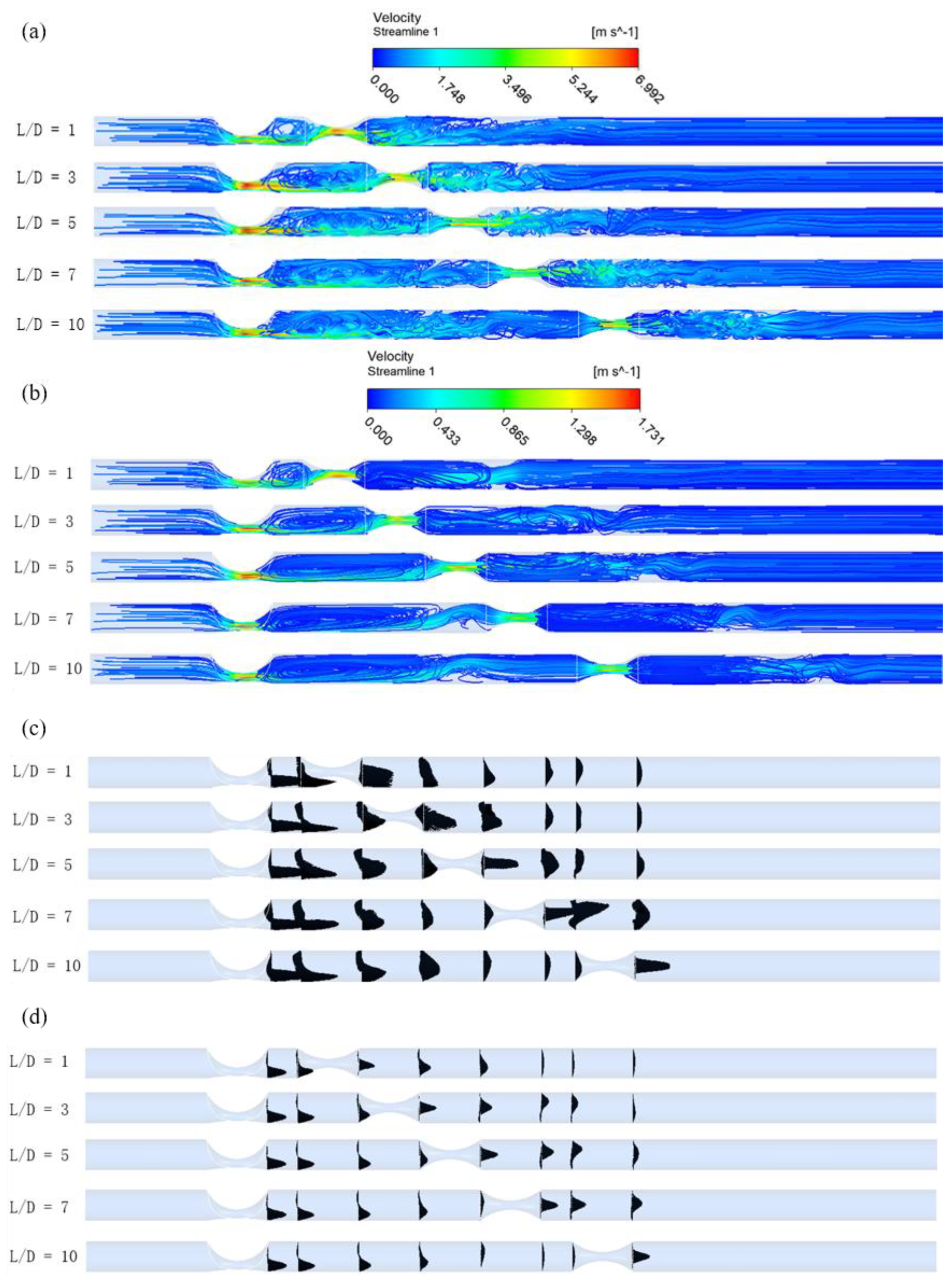
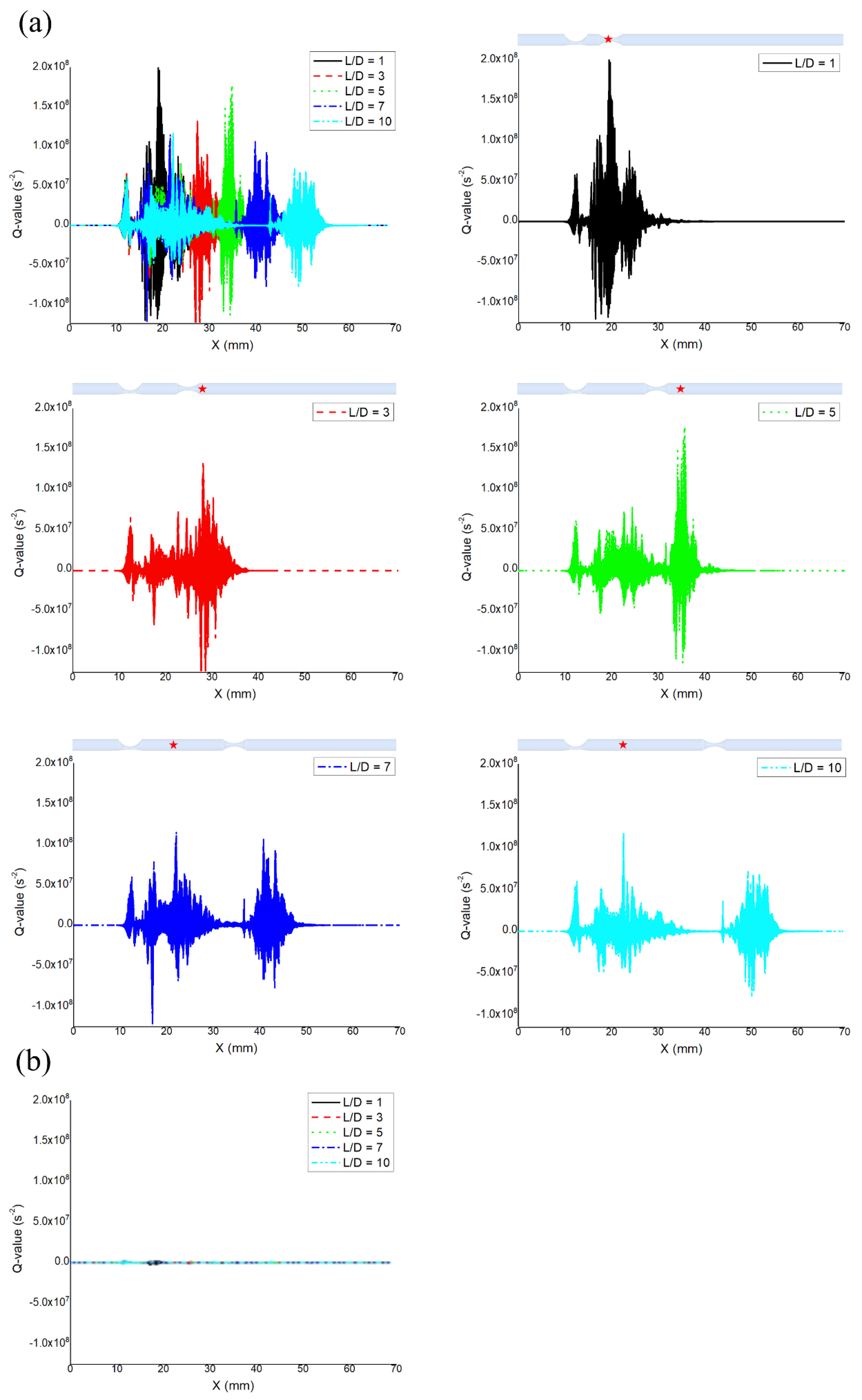
The generalized coronary artery with one eccentric stenosis (A) followed by a concentric one (B) was considered, as shown in Figure 1. This was based on the morphological observations of five hundred coronary arteries, in which 365 (73%) were eccentric and 185 (27%) were concentric [18]. The angiography in Figure 1 illustrated the clinical case with one eccentric (Stenosis A) stenosis followed by a concentric one (Stenosis B). The artery diameter (D) and total length were chosen as 2.5 mm and 70 mm, respectively [19]. The diameter stenosis was 72% for both stenoses. The eccentricity index (EI) of stenosis A was 0.875, measured by the ratio of the subtraction of the maximal ( l 1 ) and minimal ( l 2 ) thicknesses of the vessel wall to the maximal thickness (A) [20]. The spacing ratio, defined as the ratio of the distance (L) between two serial stenoses to the artery diameter (D), was adopted as 1, 3, 5, 7, and 10 [21]. Transverse planes α and β represented locations distal to each stenosis, where the pressure was measured as in clinical settings. The model was meshed with 2.69 million tetrahedral elements and 0.48 million nodes. The minimum and maximum volumes are 1.50 × 10⁻¹⁴ m 3 and 2.78 × 10⁻¹³ m 3 , as shown in Figure 1. A pulsatile inlet flow approximation by a sinusoidal profile for a cardiac cycle (T), which was 120 beats per minute [22], was adopted, as shown in Figure 2. The outlet pressure was adopted as the averaged blood pressure of 100 mmHg, i.e., 13.3 KPa for simplicity [23]. Five cardiac cycles (5T) were performed to ensure the stability of the flow. A no-slip boundary condition was implemented at the rigid arterial wall. Blood was considered as an incompressible Newtonian fluid with density, ρ, as 1035 kg/ m 3 and dynamic viscosity, μ, as 0.0035 Pa · s [24,25,26].
The incompressible blood flow was governed by the Navier-Stokes equations, i.e., conservation of momentum, along with the conservation of mass equation as shown below [27].
ρ V t + ρ ( V · ) V = P + μ 2 V
· V = 0
where pressure is denoted as P, the velocity vector as V , fluid density as ρ , and fluid viscosity as μ . SIMPLE (Semi-Implicit Method for Pressure Linked Equations) algorithm was adopted for solving the Navier-Stokes equations in the commercial package ANSYS FLUENT 17.2 (ANSYS Inc., Canonsburg, PA, USA). The first order implicit scheme was adopted for the temporal discretization for stability. The second order upwind scheme was used for the spatial discretization for high-order accuracy. The Reynolds number (Re) was estimated as 202.05. A mesh independence study was carried out to ensure that the solution was independent of the mesh density. The results with low Re and the adopted schemes could provide a reasonably accurate solution [28].
For the vortex identification, the vortex dominant region was defined with a positive second invariant (Q) of the velocity gradient tensor ( Τ ) , i.e., Q > 0 [17]. The velocity gradient tensor ( Τ ) can be decomposed into a symmetric tensor (S) and a skew-symmetric part ( Ω ) , i.e., Τ = S + Ω where S = 1 2 [( V   ) + ( V ) T )] is the rate of strain tensor and Ω = 1 2 [( V ) − ( V ) T )] is the vorticity tensor. The characteristic equation of the velocity gradient is given by
λ 3 P λ 2 + Q λ R = 0
where, P, Q, and R are the invariants of the velocity gradient tensor, which can be shown as
P = tr (T)
Q = 1 2 | Ω | 2 | S | 2
R = det (T)
The second invariant (Q) represent the local balance between the magnitude of the vorticity and the strain rate respectively. The positive second invariant (Q > 0) defines the vortices as the regions where the vorticity magnitude ( | Ω | 2 ) is greater than the strain rate magnitude ( | S | 2 ) .

3. Results

Results were retrieved at 2.1 s (systole) and 2.4 s (75% of diastole). For simplicity, the pressure ratios across a stenosis at 2.1 s were assumed to be the FFR measurement under a hyperemic condition, since the influence of the systolic phase on the averaged measurement is much stronger than that of the rest of the cardiac cycle [29]. The results at 2.4 s literally represent the iFR measurement at 75% of diastole.
The role of the spacing ratio on pressure distributions of the serial stenoses is depicted in Figure 3. Regardless of spacing ratios, two pressure valleys corresponding to the two narrowest sites were clearly observed. Following each stenosis, the local pressure fluctuation and the pressure recovery phenomenon were also observed. In systole, the pressure magnitude at the spacing ratio of 1 showed a sharp increase to 30.7 KPa at 17.8 mm away from the inlet due to the effect of high-inertia loads and the presence of a second stenosis. This sharpness was mitigated as the spacing ratio increased. This was due to the larger space between the two stenoses enabling the flow to decelerate more by the adverse pressure drop as the spacing ratio increased. It is interesting to observe that the pressure magnitude at 2.1 s in the case of the spacing ratio of 1, decreased sharply to 5.88 KPa in the center of the second stenosis. Also, the pressure variations were less than 1%, starting from 5.5D away from the first stenosis in the case of spacing ratio of 7. The same phenomenon was observed at 6.72D away from the first stenosis in the case of spacing ratio of 10. However, the pressure values fluctuated continuously from the downstream of the first stenosis to the downstream of the second stenosis in the case of the spacing ratio of 1, 3, and 5. The local pressure fluctuation became smaller distal to each of the two serial stenoses as the spacing ratio increased.
The inlet pressure was elevated as the spacing ratio increased. This resulted in a larger pressure drop across the serial stenoses considering that the outlet pressure was prescribed as constant. Specifically, the inlet pressure in the systolic phase (2.1 s) was 41.8, 42.7, 44.4, 44.4 and 44.7 KPa for the spacing ratios of 1, 3, 5, 7, and 10, respectively, resulting in pressure drops across the first stenosis of 20.2, 21.2, 18.8, 17.8, and 17.6 KPa and across the second stenosis of 8.3, 8.2, 12.3, 13.3, and 13.8 KPa, as well as total pressure drops of 28.5, 29.4, 31.1, 31.1 and 31.4 KPa, respectively.
The pressure distribution at 2.4 s also exhibited the effect of a high-inertia load at the end distal to the first stenosis, but the magnitude was significantly smaller than that at 2.1s. It is interesting to observe that the pressure variations following each stenosis at 2.4 s were less than 1%. The differences among the total pressure drops with different spacing ratios were also less than 1%.
Figure 4 shows that the recirculation zone was formed following each stenosis. It is interesting to observe that the skewed velocity profiles were returned to be the normal ones in the vicinity at the end distal to the first stenosis in the case of a spacing ratio of 7 and 10.
Figure 5 shows an instantaneous view of Q-criterion (8.531 × 10⁶ s 2 ) that corresponds to 20% of the maximum value of it. The grey-colored wormlike structures represent vortex structures. In systole (2.1 s), the distribution of the vortex structures were biased compared to those at the downstream of the second stenosis regardless of the spacing ratio. For the case of the spacing ratio of 1, 3 and 5, the vortex structures were continuously distributed from the downstream of the first stenosis to the distal to the second stenosis. However, in the case of the spacing ratio of 7 and 10, the vortex structures were not captured in vicinity at the end distal to the first stenosis, which corresponded to the locations where the pressure variations were minimal. In 75% of diastole (2.4 s), it was clearly shown that vortex structures were significantly reduced throughout the serial stenoses, compared to those at 2.1 s.
The role of the spacing ratio on Q-criterion in the artery at 2.1 s and 2.4 s is quantified in Figure 6. The Q-value represents the magnitude of Q-criterion. The locations of the maximum positive Q-value at 2.1 s are marked by the red-colored stars. These were located at 19.5 mm, 28.1 mm, 35.7 mm, 22.1 mm and 22.7 mm away from the inlet, respectively, in the case of the spacing ratio of 1, 3, 5, 7, and 10. The interesting observation was that the maximum positive Q-value at 2.1 s was located in the center of the second stenosis in the case of the spacing ratio of 1. Also, the location of the maximum positive Q-value moved toward the beginning of downstream of the second stenosis in the case of the spacing ratio of 3 and 5. However, in the case of the spacing ratio of 7 and 10, the maximum positive Q-values were located in the downstream of the first stenosis. Moreover, the averaged positive Q-values starting from the points 5.5D and 6.72D from the first stenosis to the end distal to first stenosis were 6.21 × 10⁵ s 2 , and 2.18 × 10⁵ s 2 in the case of the spacing ratio of 7 and 10, respectively, which were less than 1% of the maximum Q-value. And the maximum Q-values at 2.1 s were likely to decrease as the spacing ratio increased.
The positive maximum Q-value at 2.4 s showed a significant reduction, i.e., by 9423%, 6566%, 8471%, 5795%, and 5804%, in the positive Q-value compared to that at 2.1s in the case of the spacing ratio of 1, 3, 5, 7, and 10, respectively, which corresponded to the minimal pressure variations at 2.4s.
Figure 7 shows the representative pressure distribution with vortex structures quantified by Q-criterion (20% of maximum) at 2.1 s in the case of the spacing ratio of 5. The pressure in the region where the vortex structures existed, 18.4 mm away from the inlet, was 23.1 KPa, while a pressure not in the vortex region, i.e., 19.3 mm away from the inlet, was 26.2 KPa. The difference between them was 13.2%. The pressure difference between two points at 25.5 mm and 25.9 mm, closer to the end distal to the first stenosis, was only 2.8%. The difference between them tended to be smaller as their locations became closer to the end distal to first stenosis. The same phenomenon was observed in other cases.
Table 1 shows the FFR and iFR measurements for the first and second lesions in the case of the spacing ratio of 1, 3, 5, 7, and 10. The pressures at three locations consistent with clinical settings [30] were extracted from the models, i.e., inlet, location α and location β. The pressure ratios across each stenosis for the FFR and iFR were then calculated. Specifically, for the case with a spacing ratio of 5, the systolic pressure at inlet, location α and location β were 44.4 KPa, 25.6 KPa and 13.3KPa, respectively. The corresponding pressure at 75% diastole were 15.7 KPa, 14.3 KPa, and 13.3 KPa, respectively. The FFR measurements, i.e., systolic pressure ratios across 1st lesion and 2nd lesion, were 0.577 and 0.520, respectively. The iFR measurements, i.e., the pressure ratios at 75% diastole were 0.911, and 0.930, respectively. The difference of the FFR measurements between 1st and 2nd lesion is 19.5%, 22.8%, 11.2%, 19.8%, 23.7% in the case of the spacing ratios of 1, 3, 5, 7, and 10 respectively, showing 4.3%, 2.8%, 2.2%, 2.2%, and 0.7% in the iFR measurement. The difference of the FFR and iFR measurements between the spacing ratios of 1 and 7 were 23.6% and 1.39% respectively.

4. Discussions

The goal of this work is to quantify the hemodynamic interference in serial stenoses with different spacing ratios and its influence on the pressure measurement technique. Specifically, we examined whether the hemodynamic interference at 75% of diastole is negligible to identify the feasibility of iFR technique in serial stenoses.
The velocity streamline plot, as shown in Figure 4, enabled the qualitative identification of the hemodynamic interference, such as flow recirculation and/or the shape of velocity profile. This has been illustrated in an early numerical study [14]. However, it was unable to evaluate the impact of the hemodynamic interference on the pressure measurement without quantitative results. Therefore, we proposed to use Q-criterion for quantitatively defining the existence of vortex structures, and then hemodynamic interference in serial stenoses. The region with less than 1% of the maximum Q-value was considered as the inference-free zone. To the best of our knowledge, this is the first quantitative study in stenoses to use Q-criterion.
Local pressure fluctuation and recovery are essential for accurate pressure measurement. They were interrelated to the vortex structures, as quantified by Q-criterion in this work, as shown in Figure 7. Pressure in the vortex region was lower than those in the surrounding areas, which induces the local pressure fluctuation. This pressure variation diminished with a longer distance away from the stenosis. This is due to the pressure recovery, i.e., adverse pressure drop, associated with the flow deceleration, during which the kinetic energy was converted to the potential energy [31].
In the FFR measurements represented by systolic phase at 2.1 s, both the pressure variations and averaged Q-values had minimal changes starting from 5.5D and 6.72D downstream of the 1st stenosis in the case of spacing ratio of 7 and 10, respectively. This was considered as interference-free, which was supposed to be a pressure sensor location of FFR [30]. This interference-free zone indicated that the pressure recovery had been completed and the local pressure fluctuation by the vortex structures vanished.
A smaller spacing ratio induced a higher positive Q-value, i.e., a larger hemodynamic interference. This, in turn, causes larger errors in FFR measurements, which is consistent with current clinical speculation [11]. It is worth noting that the peak Q-values in the case of the spacing ratios of 1, 3, and 5 were located at the center of the second stenosis or further downstream, rather than the downstream of the first stenosis. This could explain that, in the case of the spacing ratio of 1, the pressure magnitude at 2.1 s decreased sharply to 5.88 KPa at the center of the second stenosis. It indicated that the pressure recovery has not been completed due to the limited spacing distance and time. The kinetic energy was only partially converted to the potential energy. Therefore, the location and distribution of the Q-value should be considered simultaneously to estimate the hemodynamic interference as well as the associated error in FFR measurements.
The FFR measurements for both the first and second lesions should be similar due to the same stenosis degree of 72%. However, the differences of the FFR measurements between the first and second lesions were greater than 19%, even in the case of the spacing ratio of 7. This is because the increased flow under hyperemia was not transmitted uniformly over the two serial stenoses [13]. A larger amount of kinetic and potential energy was converted to thermal energy by friction and viscosity when passing through the first stenosis compared to the second stenosis [32]. For example, in the case of spacing ratio of 7, the pressure drop across the first stenosis was 33.83% higher than that across 2nd stenosis, as shown in Figure 3a. This caused the underestimation of the first stenosis and overestimation of the second stenosis; this is evident in the FFR calculation (Table 1), as 0.599 and 0.500 across the first and second stenosis, respectively. This implied that, under the condition of serial stenoses, no hemodynamic interference still led to inevitable errors in FFR measurements due to the nature of the hyperemia.
In the iFR measurements, i.e., diastolic phase (2.4 s), the pressure variations distal to each stenosis were less than 1%, regardless of the spacing ratios. Even in the case of the spacing ratio of 1, the high-inertia load effect caused a difference of only 1.4% in the pressure magnitude. The hemodynamic interference, associated with the local pressure fluctuation influenced by the vortex structures, was minimal. Specifically, the maximum positive Q-value at 2.4 s was decreased by 9423% compared to that at 2.1 s. This indicated that the hemodynamic interference is negligible at 75% of diastole, which is consistent with the current clinical speculation [13].
The iFR measurements for both the first and second lesion is similar, with a difference less than 5% regardless of spacing ratios. The differences in the total pressure drop were also less than 2.2%. The differences of iFR measurements among various spacing ratios were less than 1.54%. This implied that the iFR measurement overcame the disadvantage of the FFR measurement, in which the increased flow under the hyperemic condition was not transmitted uniformly over the serial stenoses, and the hemodynamic interference was significantly amplified under hyperemia [13,33].
In the present work, the straight artery with generalized stenoses were modeled. More realistic models considering patient-specific stenoses, artery curvature, and the sequence of stenoses could be obtained from OCT (optical coherence tomography), CT (Computed Tomography) and/or MRI (Magnetic Resonance Imaging) scans. The lesions were assumed to be rigid, although they have been shown to be anisotropic, heterogeneous, and viscoelastic [34]. These simplifications might alter the magnitude of our results [35,36]. In addition, the impeded flow from guiding catheter might also alter velocity and pressure fields [30]. The dynamic outlet boundary condition will be more appropriate [37] for quantifying the hemodynamic interference and its clinical measurements. Despite these simplifications, the present work demonstrated a novel way to define the hemodynamic interference and to evaluate the measurement accuracy of both FFR and iFR, which may have significant clinical implications for diagnosis and treatment decisions of serial stenosis. In addition, although this work illustrated the feasibility of iFR measurement, it needs be further tested in clinical studies. One potential challenge could lie in the measurement resolution and the iFR threshold [38,39].

5. Conclusions

In summary, the present study proposed to use Q-criterion for quantitatively defining the hemodynamic interference in the serial stenoses considering various spacing ratios. Its impact on the FFR and iFR measurement accuracy was also evaluated. Results showed that a small spacing distance between serial stenoses induced a larger hemodynamic interference, which, in turn, caused a larger error on the pressure measurement. The FFR measurement could reach the interference-free at a large spacing ratio. It is worth noting that both the location and distribution of the Q-value should be considered simultaneously to evaluate the accuracy of the FFR measurement, considering the significantly amplified hemodynamic interference and increased flow rate in serial stenoses under hyperemic condition. The iFR measurement at 75% of diastole demonstrated a potential technique to overcome the disadvantages of FFR measurement with minimal hemodynamic interference, even for small spacing ratios. This work can be used to provide a fundamental understanding of the hemodynamic interference and its impact on pressure measurement techniques, in order to provide insights into improved functional assessments of serial stenoses.

Author Contributions

S.J. and L.G. contributed to conception, design, data acquisition, interpretation, and preparation of this manuscript.

Funding

The authors are grateful for the financial support from the National Science Foundation CAREER award (CBET-1254095).

Acknowledgments

The authors appreciate the constructive comments from Jaesung Park and Dean Jia. Thanks Pengfei Dong for proofreading this manuscript.

Conflicts of Interest

The authors declare no conflict of interest.

References

  1. Gordon, G.R.; Mulligan, S.J.; MacVicar, B.A. Astrocyte control of the cerebrovasculature. Glia 2007, 55, 1214–1221. [Google Scholar] [CrossRef] [PubMed] [Green Version]
  2. Pijls, N.H.; Fearon, W.F.; Tonino, P.A.; Siebert, U.; Ikeno, F.; Bornschein, B.; van’t Veer, M.; Klauss, V.; Manoharan, G.; Engstrøm, T.; et al. Fractional flow reserve versus angiography for guiding percutaneous coronary intervention in patients with multivessel coronary artery disease: 2-year follow-up of the FAME (Fractional Flow Reserve Versus Angiography for Multivessel Evaluation) study. J. Am. Coll. Cardiol. 2010, 56, 177–184. [Google Scholar] [CrossRef] [PubMed]
  3. Tebaldi, M.; Campo, G.; Biscaglia, S. Fractional flow reserve: Current applications and overview of the available data. World J. Clin. Cases 2015, 3, 678–681. [Google Scholar] [CrossRef] [PubMed]
  4. Tanaka, K.; Bezerra, H.G.; Gaur, S.; Attizzani, G.F.; Bøtker, H.E.; Costa, M.A.; Rogers, C.; Nørgaard, B.L. Comparison between non-invasive (coronary computed tomography angiography derived) and invasive-fractional flow reserve in patients with serial stenoses within one Coronary artery: A NXT trial substudy. Ann. Biomed. Eng. 2016, 44, 580–589. [Google Scholar] [CrossRef] [PubMed]
  5. De Bruyne, B.; Pijls, N.H.; Heyndrickx, G.R.; Hodeige, D.; Kirkeeide, R.; Gould, K.L. Pressure-derived fractional flow reserve to assess serial epicardial stenoses: Theoretical basis and animal validation. Circulation 2000, 101, 1840–1847. [Google Scholar] [CrossRef]
  6. Siebert, U.; Arvandi, M.; Gothe, R.M.; Bornschein, B.; Eccleston, D.; Walters, D.L.; Rankin, J.; De Bruyne, B.; Fearon, W.F.; Pijls, N.H.; et al. Improving the quality of percutaneous revascularisation in patients with multivessel disease in Australia: Cost-effectiveness, public health implications, and budget impact of FFR-guided PCI. Heart Lung Circ. 2014, 23, 527–533. [Google Scholar] [CrossRef] [PubMed]
  7. Modi, B.; Chattersingh, A.; Ryan, M.; Ellis, H.; Lee, J.; Gaddum, N.; Chowienczyk, P.; Perera, D. P3322Optimising physiological assessment of serial coronary artery lesions using an in vitro model of tandem stenoses. Eur. Heart J. 2017, 38 (Suppl. 1). [Google Scholar] [CrossRef] [Green Version]
  8. Sen, S.; Asrress, K.N.; Nijjer, S.; Petraco, R.; Malik, I.S.; Foale, R.A.; Mikhail, G.W.; Foin, N.; Broyd, C.; Hadjiloizou, N.; et al. Diagnostic classification of the instantaneous wave-free ratio is equivalent to fractional flow reserve and is not improved with adenosine administration: Results of CLARIFY (Classification Accuracy of Pressure-Only Ratios Against Indices Using Flow Study). J. Am. Coll. Cardiol. 2013, 61, 1409–1420. [Google Scholar] [CrossRef] [PubMed]
  9. Nijjer, S.S.; Sen, S.; Petraco, R.; Escaned, J.; Echavarria-Pinto, M.; Broyd, C.; Al-Lamee, R.; Foin, N.; Foale, R.A.; Malik, I.S.; et al. Pre-angioplasty instantaneous wave-free ratio pullback provides virtual intervention and predicts hemodynamic outcome for serial lesions and diffuse coronary artery disease. JACC Cardiovasc. Interv. 2014, 7, 1386–1396. [Google Scholar] [CrossRef] [PubMed]
  10. De Rosa, S.; Polimeni, A.; Petraco, R.; Davies, J.E.; Indolfi, C. Diagnostic performance of the instantaneous wave-free ratio: Comparison with fractional flow reserve. Circ. Cardiovasc. Interv. 2018, 11, e004613. [Google Scholar] [CrossRef] [PubMed]
  11. Modi, B.N.; De Silva, K.; Rajani, R.; Curzen, N.; Perera, D. Physiology-guided management of serial coronary artery disease: A review. JAMA Cardiol. 2018, 3, 432–438. [Google Scholar] [CrossRef] [PubMed]
  12. Sen, S.; Escaned, J.; Malik, I.S.; Mikhail, G.W.; Foale, R.A.; Mila, R.; Tarkin, J.; Petraco, R.; Broyd, C.; Jabbour, R.; et al. Development and validation of a new adenosine-independent index of stenosis severity from coronary wave-intensity analysis: Results of the ADVISE (ADenosine Vasodilator Independent Stenosis Evaluation) study. J. Am. Coll. Cardiol. 2012, 59, 1392–1402. [Google Scholar] [CrossRef] [PubMed]
  13. Nijjer, S.S.; Sen, S.; Petraco, R.; Mayet, J.; Francis, D.P.; Davies, J.E. The Instantaneous wave-Free Ratio (iFR) pullback: A novel innovation using baseline physiology to optimise coronary angioplasty in tandem lesions. Cardiovasc. Revasc. Med. 2015, 16, 167–171. [Google Scholar] [CrossRef] [PubMed]
  14. Lee, T.; Liao, W.; Low, H. Numerical simulation of turbulent flow through series stenoses. Int. J. Numer. Methods Fluids 2003, 42, 717–740. [Google Scholar] [CrossRef]
  15. Liu, X.; Peng, C.; Xia, Y.; Gao, Z.; Xu, P.; Wang, X.; Xian, Z.; Yin, Y.; Jiao, L.; Wang, D.; et al. Hemodynamics analysis of the serial stenotic coronary arteries. Biomed. Eng. Online 2017, 16, 127. [Google Scholar] [CrossRef] [Green Version]
  16. Chen, X.; Gao, Y.; Lu, B.; Jia, X.; Zhong, L.; Kassab, G.S.; Tan, W.; Huo, Y. Hemodynamics in coronary arterial tree of serial stenoses. PLoS ONE 2016, 11, e0163715. [Google Scholar] [CrossRef] [PubMed]
  17. Hunt, J.C.; Wray, A.A.; Moin, P. Eddies, Streams, and Convergence Zones in Turbulent Flows. In Proceedings of the Summer Program 1988; Center for Turbulence Research: Stanford, CA, USA, 1988. [Google Scholar]
  18. Waller, B.F. The eccentric coronary atherosclerotic plaque: Morphologic observations and clinical relevance. Clin. Cardiol. 1989, 12, 14–20. [Google Scholar] [CrossRef] [Green Version]
  19. Pijls, N.H.; De Bruyne, B.; Bech, G.J.; Liistro, F.; Heyndrickx, G.R.; Bonnier, H.J.; Koolen, J.J. Coronary pressure measurement to assess the hemodynamic significance of serial stenoses within one coronary artery: Validation in humans. Circulation 2000, 102, 2371–2377. [Google Scholar] [CrossRef]
  20. Ohara, T.; Toyoda, K.; Otsubo, R.; Nagatsuka, K.; Kubota, Y.; Yasaka, M.; Naritomi, H.; Minematsu, K. Eccentric stenosis of the carotid artery associated with ipsilateral cerebrovascular events. Am. J. Neuroradiol. 2008, 29, 1200–1203. [Google Scholar] [CrossRef] [PubMed]
  21. Kern, M.J.; Lerman, A.; Bech, J.W.; De Bruyne, B.; Eeckhout, E.; Fearon, W.F.; Higano, S.T.; Lim, M.J.; Meuwissen, M.; Piek, J.J.; et al. Physiological assessment of coronary artery disease in the cardiac catheterization laboratory. Circulation 2006, 114, 1321–1341. [Google Scholar] [CrossRef]
  22. Sinnott, M.; Cleary, P.W.; Prakash, M. An investigation of pulsatile blood flow in a bifurcation artery using a grid-free method. In Proceedings of the Fifth International Conference on CFD in the Process Industries (CSIRO), Melbourne, Australia, 13–15 December 2006. [Google Scholar]
  23. Gribbin, B.; Pickering, T.G.; Sleight, P.; Peto, R. Effect of age and high blood pressure on barorefiex sensitivity in man. Circ. Res. 1971, 29, 424–431. [Google Scholar] [CrossRef] [PubMed]
  24. Olufsen, M.S.; Peskin, C.S.; Kim, W.Y.; Pedersen, E.M.; Nadim, A.; Larsen, J. Numerical simulation and experimental validation of blood flow in arteries with structured-tree outflow conditions. Ann. Biomed. Eng. 2000, 28, 1281–1299. [Google Scholar] [CrossRef]
  25. Perktold, K.; Peter, R.O.; Resch, M.; Langs, G. Pulsatile non-Newtonian blood flow in three-dimensional carotid bifurcation models: A numerical study of flow phenomena under different bifurcation angles. J. Biomed. Eng. 1991, 13, 507–515. [Google Scholar] [CrossRef]
  26. Noutchie, S.C.O. Flow of a Newtonian Fluid: The Case of Blood in Large Arteries. Master’s Thesis, University of South Africa, Pretoria, South Africa, November 2005. [Google Scholar]
  27. Temam, R. Navier—Stokes Equations; North-Holland: Amsterdam, The Netherlands, 1984; Volume 2. [Google Scholar]
  28. Mouza, A.; Skordia, O.D.; Tzouganatos, I.D.; Paras, S.V. A simplified model for predicting friction factors of laminar blood flow in small-caliber vessels. Fluids 2018, 3, 75. [Google Scholar] [CrossRef]
  29. Kapoor, N.; Fahsah, I.; Karim, R.; Jevans, A.J.; Leesar, M.A. Physiological assessment of renal artery stenosis: Comparisons of resting with hyperemic renal pressure measurements. Catheter. Cardiovasc. Interv. 2010, 76, 726–732. [Google Scholar] [CrossRef] [PubMed]
  30. Toth, G.G.; Johnson, N.P.; Jeremias, A.; Pellicano, M.; Vranckx, P.; Fearon, W.F.; Barbato, E.; Kern, M.J.; Pijls, N.H.; De Bruyne, B. Standardization of fractional flow reserve measurements. J. Am. Coll. Cardiol. 2016, 68, 742–753. [Google Scholar] [CrossRef]
  31. Bach, D.S. Echo/Doppler evaluation of hemodynamics after aortic valve replacement: Principles of interrogation and evaluation of high gradients. JACC Cardiovasc. Imaging 2010, 3, 296–304. [Google Scholar] [CrossRef]
  32. Barker, A.J.; van Ooij, P.; Bandi, K.; Garcia, J.; Albaghdadi, M.; McCarthy, P.; Bonow, R.O.; Carr, J.; Collins, J.; Malaisrie, S.C.; et al. Viscous energy loss in the presence of abnormal aortic flow. Magn. Reson. Med. 2014, 72, 620–628. [Google Scholar] [CrossRef]
  33. Gould, K.L. Pressure-flow characteristics of coronary stenoses in unsedated dogs at rest and during coronary vasodilation. Circ. Res. 1978, 43, 242–253. [Google Scholar] [CrossRef]
  34. Buchmann, N.A.; Jermy, M.C. Blood flow measurements in idealised and patient specific models of the human carotid artery. In Proceedings of the 14th International Symposium on Applications of Laser Techniques to Fluid Mechanics, Lisbon, Portugal, 7–10 July 2008. [Google Scholar]
  35. Govindaraju, K.; Viswanathan, G.N.; Badruddin, I.A.; Kamangar, S.; Salman Ahmed, N.J.; Al-Rashed, A.A. The influence of artery wall curvature on the anatomical assessment of stenosis severity derived from fractional flow reserve: A computational fluid dynamics study. Comput. Methods Biomech. Biomed. Eng. 2016, 19, 1541–1549. [Google Scholar] [CrossRef]
  36. Lin, S.; Han, X.; Bi, Y.; Ju, S.; Gu, L. Fluid-structure interaction in abdominal aortic aneurysm: Effect of modeling techniques. BioMed Res. Int. 2017, 2017. [Google Scholar] [CrossRef] [PubMed]
  37. Liu, B.; Zheng, J.; Bach, R.; Tang, D. Influence of model boundary conditions on blood flow patterns in a patient specific stenotic right coronary artery. Biomed. Eng. Online 2015, 14, S6. [Google Scholar] [CrossRef] [PubMed] [Green Version]
  38. Kobayashi, Y.; Johnson, N.P.; Berry, C.; De Bruyne, B.; Gould, K.L.; Jeremias, A.; Oldroyd, K.G.; Pijls, N.H.J.; Fearon, W.F. CONTRAST Study Investigators. The influence of lesion location on the diagnostic accuracy of adenosine-free coronary pressure wire measurements. JACC Cardiovasc. Interv. 2016, 9, 2390–2399. [Google Scholar] [CrossRef] [PubMed]
  39. Pisters, R.; Ilhan, M.; Veenstra, L.F.; Gho, B.C.G.; Stein, M.; Hoorntje, J.C.A.; Rasoul, S. Instantaneous wave-free ratio and fractional flow reserve in clinical practice. Neth. Heart J. 2018, 1–8. [Google Scholar] [CrossRef] [PubMed]
Figure 1. Top: Schematic diagram of serial stenoses with one eccentric stenosis (A) followed by one concentric stenosis (B) (unit, mm); Bottom: Definition of eccentricity Index (EI); (C) Angiography of eccentric (Stenosis A) and concentric stenosis (Stenosis B); (D) enlarged view of mesh at inlet; (E) 3-Dimensional view of mesh for coronary artery.
Applsci 09 00279 g001
Figure 2. Pulsatile velocity profile at the inlet.
Applsci 09 00279 g002
Figure 3. Pressure distributions in the case of the spacing ratio of 1, 3, 5, 7 and 10 at 2.1 s (a) and 2.4 s (b).
Applsci 09 00279 g003
Figure 4. Velocity streamlines at 2.1 s (a) and 2.4 s (b) and velocity plane profiles at 2.1 s (c) and 2.4 s (d) in the case of the spacing ratio of 1, 3, 5, 7 and 10.
Applsci 09 00279 g004
Figure 5. Vortex structures, 20% of the maximum value of Q-criterion (8.531 × 10⁶ s 2 ) in the case of the spacing ratio of 1, 3, 5, 7 and 10 at 2.1 s (a) and 2.4 s (b).
Applsci 09 00279 g005
Figure 6. Q-values in the case of the spacing ratio of 1, 3, 5, 7 and 10 at 2.1 s (a) and at 2.4 (b). The red stars represent the locations of the maximum Q-value at 2.1 s.
Applsci 09 00279 g006
Figure 7. Representative pressure distribution with vortex structures quantified by Q-criterion (20% of maximum) at 2.1 s in the case of the spacing ratio of 5.
Applsci 09 00279 g007
Table 1. FFR, and iFR for 1st lesion and 2nd lesion in the case of the spacing ratio of 1, 3, 5, 7, and 10.
Spacing Ratio (L/D)FFR (1st Lesion/2nd Lesion)iFR (1st Lesion/2nd Lesion)
10.517/0.6180.904/0.943
30.503/0.6180.910/0.936
50.577/0.5200.911/0.930
70.599/0.5000.911/0.930
100.606/0.4900.917/0.923

