High-Transmittance 2π Electrically Tunable Terahertz Phase Shifter with CMOS-Compatible Driving Voltage Enabled by Liquid Crystals

 ,
, 

Abstract
1. Introduction
2. Experimental Methods
3. Theoretical Formulism
4. Results and Discussions
5. Conclusions
Author Contributions
Funding
Acknowledgments
Conflicts of Interest
References
- Shi, J.-W.; Huang, C.-B.; Pan, C.-L. Millimeter-wave photonic wireless links for very-high data rate communication. NPG Asia Mater. 2011, 3, 41–48. [Google Scholar] [CrossRef]
- Chen, C.-Y.; Hsieh, C.-F.; Lin, Y.-F.; Pan, R.-P.; Pan, C.-L. Magnetically tunable room-temperature 2π liquid crystal terahertz phase shifter. Opt. Express 2004, 12, 2630–2635. [Google Scholar] [CrossRef]
- Wu, H.-Y.; Hsieh, C.-F.; Tang, T.-T.; Pan, R.-P.; Pan, C.-L. Electrically tunable room-temperature 2π liquid crystal terahertz phase shifter. IEEE Photonic Technol. Lett. 2006, 18, 1488–1490. [Google Scholar]
- Yang, C.-S.; Kuo, C.; Tang, C.-C.; Chen, J.C.; Pan, R.-P.; Pan, C.-L. Liquid-crystal terahertz quarter-wave plate using chemical-vapor-deposited graphene electrodes. IEEE Photonics J. 2015, 7, 2200808. [Google Scholar] [CrossRef]
- Yang, C.-S.; Tang, T.-T.; Pan, R.-P.; Yu, P.; Pan, C.-L. Liquid crystal terahertz phase shifters with functional indium-tin-oxide nanostructure for biasing and alignment. Appl. Phys. Lett. 2014, 104, 141106. [Google Scholar] [CrossRef]
- Lin, X.-W.; Wu, J.-B.; Hu, W.; Zheng, Z.-G.; Wu, Z.-J.; Zhu, G.; Xu, F.; Jin, B.-B.; Lu, Y.-Q. Self-polarizing terahertz liquid crystal phase shifter. AIP Adv. 2011, 1, 032133. [Google Scholar] [CrossRef]
- Altmann, K.; Reuter, M.; Garbat, K.; Koch, M.; Dabrowski, R.; Dierking, I. Polymer stabilized liquid crystal phase shifter for terahertz waves. Opt. Express 2013, 21, 12395–12400. [Google Scholar] [CrossRef] [PubMed]
- Wu, Y.; Ruan, X.; Chen, C.-H.; Shin, Y.J.; Lee, Y.; Niu, J.; Liu, J.; Chen, Y.; Yang, K.-L.; Zhang, X.; et al. Graphene/liquid crystal based terahertz phase shifters. Opt. Express 2013, 21, 21395–21402. [Google Scholar] [CrossRef] [PubMed]
- Du, Y.; Tian, H.; Cui, X.; Wang, H.; Zhou, Z.-X. Electrically tunable liquid crystal terahertz phase shifter driven by transparent polymer electrodes. J. Mater. Chem. C 2016, 4, 4138–4142. [Google Scholar] [CrossRef]
- Sasaki, T.; Noda, K.; Kawatsuki, N.; Ono, H. Universal polarization terahertz phase controllers using randomly aligned liquid crystal cells with graphene electrodes. Opt. Lett. 2015, 40, 1544–1547. [Google Scholar] [CrossRef] [PubMed]
- Sasaki, T.; Okuyama, H.; Sakamoto, M.; Noda, K.; Okamoto, H.; Kawatsuki, N.; Ono, H. Twisted nematic liquid crystal cells with rubbed poly(3,4-ethylenedioxythiophene)/poly(styrenesulfonate) films for active polarization control of terahertz waves. J. Appl. Phys. 2017, 121, 143106. [Google Scholar] [CrossRef]
- Sasaki, T.; Kushida, H.; Sakamoto, M.; Noda, K.; Okamoto, H.; Kawatsuki, N.; Ono, H. Liquid crystal cells with subwavelength metallic gratings for transmissive terahertz elements with electrical tunability. Opt. Commun. 2019, 431, 63–67. [Google Scholar] [CrossRef]
- Vasić, B.; Zografopoulos, D.C.; Isić, G.; Beccherelli, R.; Gajić, R. Electrically tunable terahertz polarization converter based on overcoupled metal-isolator-metal metamaterials infiltrated with liquid crystals. Nanotechnology 2017, 28, 124002. [Google Scholar] [CrossRef] [PubMed]
- Chen, C.-Y.; Pan, C.-L.; Hsieh, C.-F.; Lin, Y.-F.; Pan, R.-P. Liquid-crystal-based terahertz tunable Lyot filter. Appl. Phys. Lett. 2006, 88, 101107. [Google Scholar] [CrossRef]
- Lin, C.-J.; Li, Y.-T.; Hsieh, C.-F.; Pan, R.-P.; Pan, C.-L. Manipulating terahertz wave by a magnetically tunable liquid crystal phase grating. Opt. Express 2008, 16, 2995–3001. [Google Scholar] [CrossRef] [PubMed]
- Hsieh, C.-F.; Lai, Y.-C.; Pan, R.-P.; Pan, C.-L. Polarizing terahertz waves with nematic liquid crystals. Opt. Lett. 2008, 33, 1174–1176. [Google Scholar] [CrossRef] [PubMed]
- Xie, Z.; Wang, X.; Ye, J.; Feng, S.; Sun, W.; Akalin, T.; Zhang, Y. Spatial terahertz modulator. Sci. Rep. 2013, 3, 3347. [Google Scholar] [CrossRef]
- Yang, C.-S.; Chang, C.-M.; Chen, P.-H.; Yu, P.; Pan, C.-L. Broadband terahertz conductivity and optical transmission of indium-tin-oxide (ITO) nanomaterials. Opt. Express 2013, 21, 16670–16682. [Google Scholar] [CrossRef] [PubMed]
- Yang, C.-S.; Lin, M.-H.; Chang, C.-H.; Yu, P.; Shieh, J.-M.; Shen, C.-H.; Wada, O.; Pan, C.-L. Non-Drude behavior in indium-tin-oxide nanowhiskers and thin films investigated by transmission and reflection THz time-domain spectroscopy. IEEE J. Quantum Electron. 2013, 49, 677–690. [Google Scholar] [CrossRef]
- Pan, C.-L.; Yang, C.-S.; Pan, R.-P.; Yu, P.; Lin, G.-R. Nanostructured Indium Tin Oxides and other Transparent Conducting Oxides: Characteristics and Applications in the THz Frequency Range. In Terahertz Spectroscopy—A Cutting Edge Technology; Chapter 14; Uddin, J., Ed.; InTech Open: London, UK, 2017; pp. 267–286. [Google Scholar]
- Pan, C.-L.; Chao, R.-P.; Chen, C.-Y. Tunable THz Phase Shifters by Magnetic-Field-Controlled Birefringence in Liquid Crystals. Taiwan (ROC) Patent 200186, 11 April 2004. [Google Scholar]
- Pan, C.-L.; Pan, R.-P.; Yang, C.-S.; Yu, P. Voltage-controlled 2π liquid-crystal terahertz phase shifter with indium-tin-oxide (ITO) nanowhiskers as transparent electrodes. In Proceedings of the XXXI General Assembly of the International Union of Radio Science, Beijing, China, 16–13 August 2014. Paper DFC01.6. [Google Scholar]
- Yeh, P.; Gu, C. Optics of Liquid Crystal Displays; Wiley: Hoboken, NJ, USA, 1999. [Google Scholar]
- Ku, C.-P.; Shih, C.-C.; Lin, C.-J.; Pan, R.-P.; Pan, C.-L. THz Optical Constants of the Liquid Crystal MDA-00-3461. Mol. Cryst. Liquid Cryst. 2011, 541, 303–308. [Google Scholar] [CrossRef]


| Type A | Type B | Type C | |
|---|---|---|---|
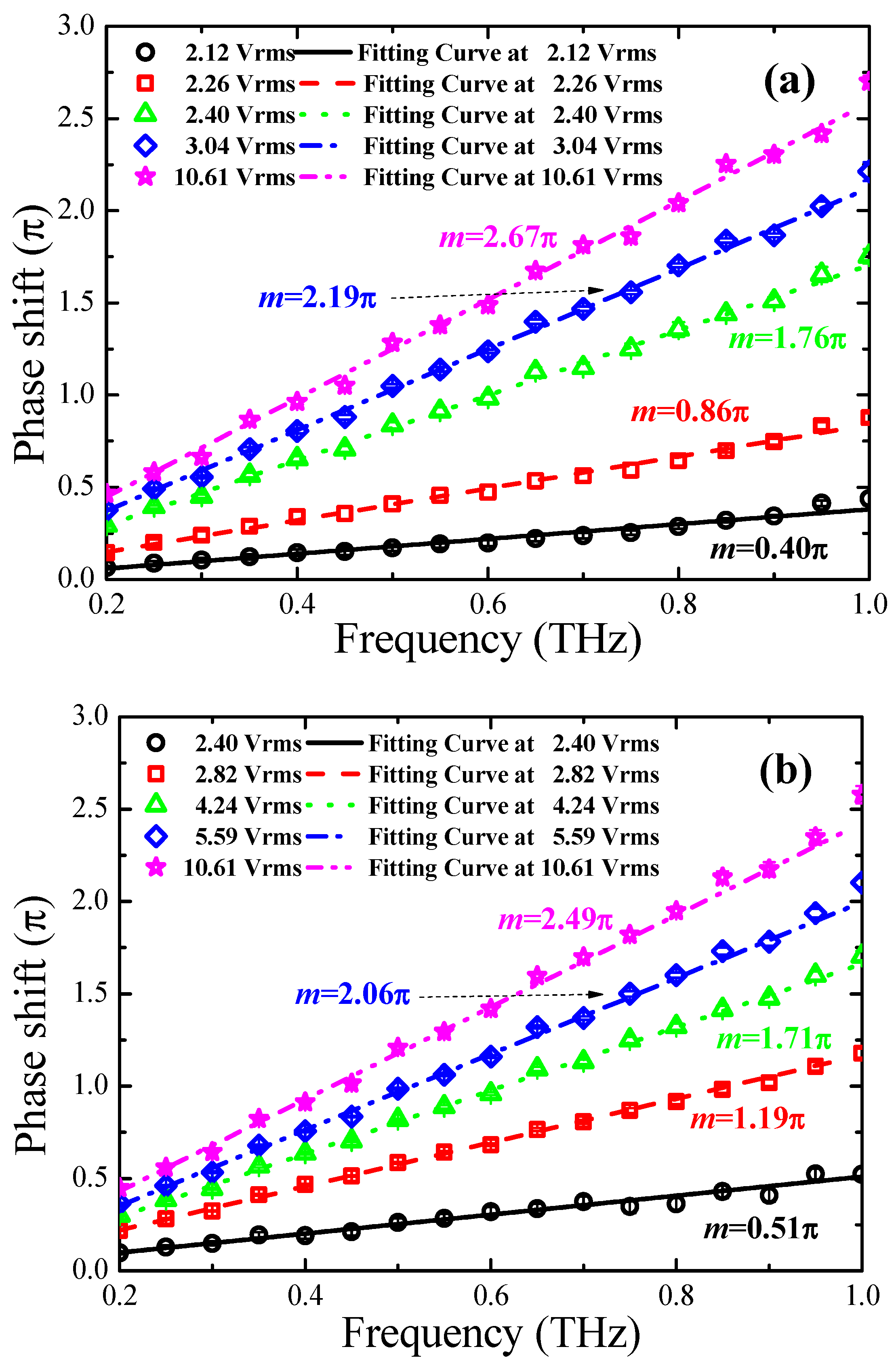
| ∆ϕE at 1 THz | 2.750π | 2.832π | 2.690π |
| ∆nE | 0.183 | 0.191 | 0.177 |
| θ0 | 19.07° | 15.98° | 21.42° |
| α | 1.064 | 1.081 | 1.187 |
| β | 0.915 | 0.955 | 0.885 |
| Bias voltage for 2π phase shift at 1.0 THz V (rms) | 2.6 | 5.3 | 10.3 |
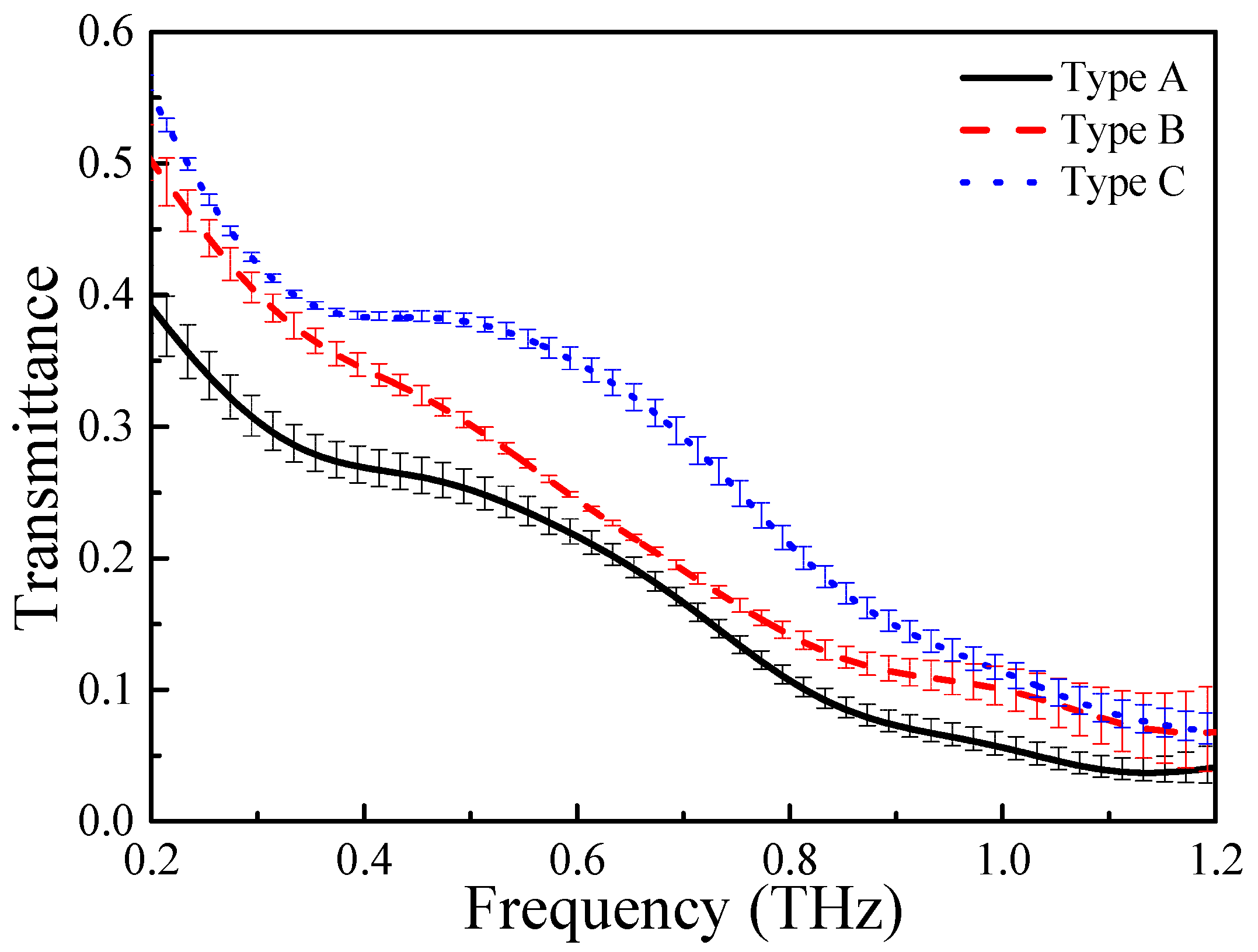
| Averaged transmittance | 20.0% | 25.4% | 31.3% |
© 2019 by the authors. Licensee MDPI, Basel, Switzerland. This article is an open access article distributed under the terms and conditions of the Creative Commons Attribution (CC BY) license (http://creativecommons.org/licenses/by/4.0/).
Share and Cite
Yang, C.-S.; Kuo, C.; Chen, P.-H.; Wu, W.-T.; Pan, R.-P.; Yu, P.; Pan, C.-L. High-Transmittance 2π Electrically Tunable Terahertz Phase Shifter with CMOS-Compatible Driving Voltage Enabled by Liquid Crystals. Appl. Sci. 2019, 9, 271. https://doi.org/10.3390/app9020271
Yang C-S, Kuo C, Chen P-H, Wu W-T, Pan R-P, Yu P, Pan C-L. High-Transmittance 2π Electrically Tunable Terahertz Phase Shifter with CMOS-Compatible Driving Voltage Enabled by Liquid Crystals. Applied Sciences. 2019; 9(2):271. https://doi.org/10.3390/app9020271
Chicago/Turabian StyleYang, Chan-Shan, Chun Kuo, Po-Han Chen, Wei-Ta Wu, Ru-Pin Pan, Peichen Yu, and Ci-Ling Pan. 2019. "High-Transmittance 2π Electrically Tunable Terahertz Phase Shifter with CMOS-Compatible Driving Voltage Enabled by Liquid Crystals" Applied Sciences 9, no. 2: 271. https://doi.org/10.3390/app9020271
APA StyleYang, C.-S., Kuo, C., Chen, P.-H., Wu, W.-T., Pan, R.-P., Yu, P., & Pan, C.-L. (2019). High-Transmittance 2π Electrically Tunable Terahertz Phase Shifter with CMOS-Compatible Driving Voltage Enabled by Liquid Crystals. Applied Sciences, 9(2), 271. https://doi.org/10.3390/app9020271