Article

Ultraprecision Diameter Measurement of Small Holes with Large Depth-To-Diameter Ratios Based on Spherical Scattering Electrical-Field Probing

Center of Ultra-Precision Optoelectronic Instrument, Harbin Institute of Technology, Harbin 150080, China
*
Author to whom correspondence should be addressed.
Appl. Sci. 2019, 9(2), 242; https://doi.org/10.3390/app9020242
Submission received: 6 December 2018 / Revised: 28 December 2018 / Accepted: 6 January 2019 / Published: 10 January 2019
(This article belongs to the Special Issue Precision Dimensional Measurements)

Abstract

:

Featured Application

This measurement method has been successfully applied in the aviation, aerospace, and automotive industries, especially for the ultraprecision manufacturing of key parts and small structures with large aspect ratios.

Abstract

In order to solve the difficulty of precision measurement of small hole diameters with large depth-to-diameter ratios, a new measurement method based on spherical scattering electrical-field probing (SSEP) was developed. A spherical scattering electrical field with identical sensing characteristics in arbitrary spatial directions was formed to convert the micro gap between the probing-ball and the part being measured into an electrical signal. 3D non-contact probing, nanometer resolution, and approximate point probing—which are key properties for high measurement precision and large measurable depth-to-diameter ratios—were achieved. A specially designed hole diameter measuring machine (HDMM) was developed, and key techniques, including laser interferometry for macro displacement measurement of the probe, multi-degree-of-freedom adjustment of hole attitude, and measurement process planning, are described. Experiments were carried out using the HDMM and a probing sensor with a ϕ3-mm probing ball and a 150-mm-long stylus to verify the performance of the probing sensor and the measuring machine. The experimental results indicate that the resolution of the probing sensor was as small as 1 nm, and the expanded uncertainty of measurement result was 0.2 μm (k = 2) when a ϕ20-mm ring gauge standard was measured.

Graphical Abstract

1. Introduction

Deep and small holes with diameters in the range of 1–10 mm and large depth-to-diameter ratios are more and more widely used in the aviation, aerospace, and automotive industries [1]. The depth-to-diameter ratio of these precisely manufactured small holes often reaches a value up to several tens, even several hundred [2,3]. These deep and small holes present great challenges to the measurable depth-to-diameter ratio and the precision of existing measurement methods.
A contact probe can go deep into small holes with a long stylus or extension rod. However, stylus bending and contact deformation of the probing head as well as the part being measured significantly limit the measurable depth and precision. Some research has aimed tried to reduce the probing force to several mN [4,5], but high measurable depth and high precision cannot be achieved at the same time. Noncontact probing methods are promising solutions to this challenge [6,7,8]. Of all the noncontact probing methods, optical methods are more promising to obtain higher resolution and precision [9,10,11,12]. Based on various “optical needle” principles, nanometer resolution can be easily achieved. However, applying optical probes in deep and small hole measurement is difficult because optical probes usually have only 1D nanometer resolution probing ability and are, thus, more suitable for 2D and 2 1 2 D structure measurement, such as for the shape measurement of a shallow optical surface. A variety of micro and nano probes with nanometer resolution and high stylus aspect ratio have been developed [13,14,15]. However, these probes are relatively small and more suitable for the measurement of micro/nano structures. Additionally, their stylus length and measurable depth is limited to several millimeters.
Aside from the demand for new probing methods, other difficulties need to be solved to realize ultraprecision measurement of deep and small holes, such as multi-degree-of-freedom adjustment of hole attitude and macro displacement measurement of the probe.
In this paper, a patented ultraprecision measurement method [16] based on spherical scattering electrical-field probing (SSEP) is proposed, and a hole diameter measuring machine (HDMM) is specially designed and developed. Key techniques such as multi-degree-of-freedom adjustment of hole attitude, laser interferometry for macro displacement measurement of the probe, and hole diameter measurement process planning are described. Finally, experiments are carried out with the HDMM and a probe that is specifically developed for method verification.

2. Spherical Scattering Electrical-Field Probing Method

The model of small hole diameter measurement with a non-contact probe can be expressed as:
D = l + d + δ 1 + δ 2
where D is the hole diameter to be measured; d is the probing ball diameter; l is the macro displacement of the probe when it is moved from the first probing point to the second along the measurement line of the diameter; and δ 1 and δ 2 are micro probing gaps between the probing ball and the hole sidewall at the two probing points.
In the proposed measurement method based on SSEP, d was calibrated beforehand, l was obtained using laser interferometry, and δ 1 and δ 2 were given by the SSEP probe. The quality of the diameter measurements depended on the ability to accurately determine δ 1 and δ 2 .
The principle of the SSEP method is shown in Figure 1. The probing ball and the small hole are electrically conductive. When the probing ball probes the internal sidewall of the hole, a dual conductor system is formed. By constructing certain boundary conditions—e.g., grounding the hole and keeping the potential of the probing ball constant—a spherical scattering electrical field is formed, and the electrical field between the probing ball and the hole sidewall, as well as the distribution of surface charge, is strongly affected by the micro probing gap. Based on this phenomenon, the micro gap between the probing ball and the hole sidewall is converted to a capacitive signal and detected with capacitive signal processing circuits [17].
The sensing characteristics of the spherical scattering electrical field is identical in arbitrary spatial directions. Therefore, the measurement performance is not influenced by the relative attitude between the probe and the hole to be measured, which is often a key limitation in existing non-contact high-precision probing methods of small holes with large depth-to-diameter ratios.
Considering the actual demand in industry, only holes of conductor material are discussed—although the analysis shows that non-conductor material can also be probed using the SSEP method with much worse resolution.
The bias electrical field was theoretically modeled using the seven-point finite difference method and non-uniform meshing in a spherical coordinate system [18]. The Laplace equation was solved for a model consisting of a ϕ3-mm conductor sphere as the probing ball and a conducting plane (yoz plane) as the surface to be measured. The potential of the sphere was 1V and the plane was grounded. The probing gap was set to 0.2 μm. The simulation software was programmed by the authors with MATLAB (MathWorks, Natick, Massachusetts, US). The surface charge density characteristics of the probing ball are shown in Figure 2. It is shown that most surface charge on the probing ball was concentrated in a very small area closest to the part being measured, and 43% of the surface charge was concentrated in an area comprising 1% of the whole surface area of the probing ball. The charge density of the waist line of the probing ball is shown in the top right corner of Figure 2, and the curve is characterized by a single peak. This phenomenon indicates that the SSEP probe has a point probing capability. Therefore, the SSEP probe is capable of isotropic sensing and point-probing, both of which are ideal for the measurement of small holes with large depth-to-diameter ratios.
Figure 3a shows the relationship between the surface area ratio, defined as the ratio of the charge concentrating area to the whole surface area of the probing ball, and the corresponding surface charge ratio when a ϕ3-mm probing ball probes holes of different diameters with a 0.2-μm probing gap. Figure 3b shows the relationship of the surface area ratio to surface charge ratio when a ϕ3-mm probing ball probes a ϕ12-mm hole with a probing gap from 0.2 μm to 1 μm. It can be observed that the surface charge concentration was similar when holes of different diameters were probed.
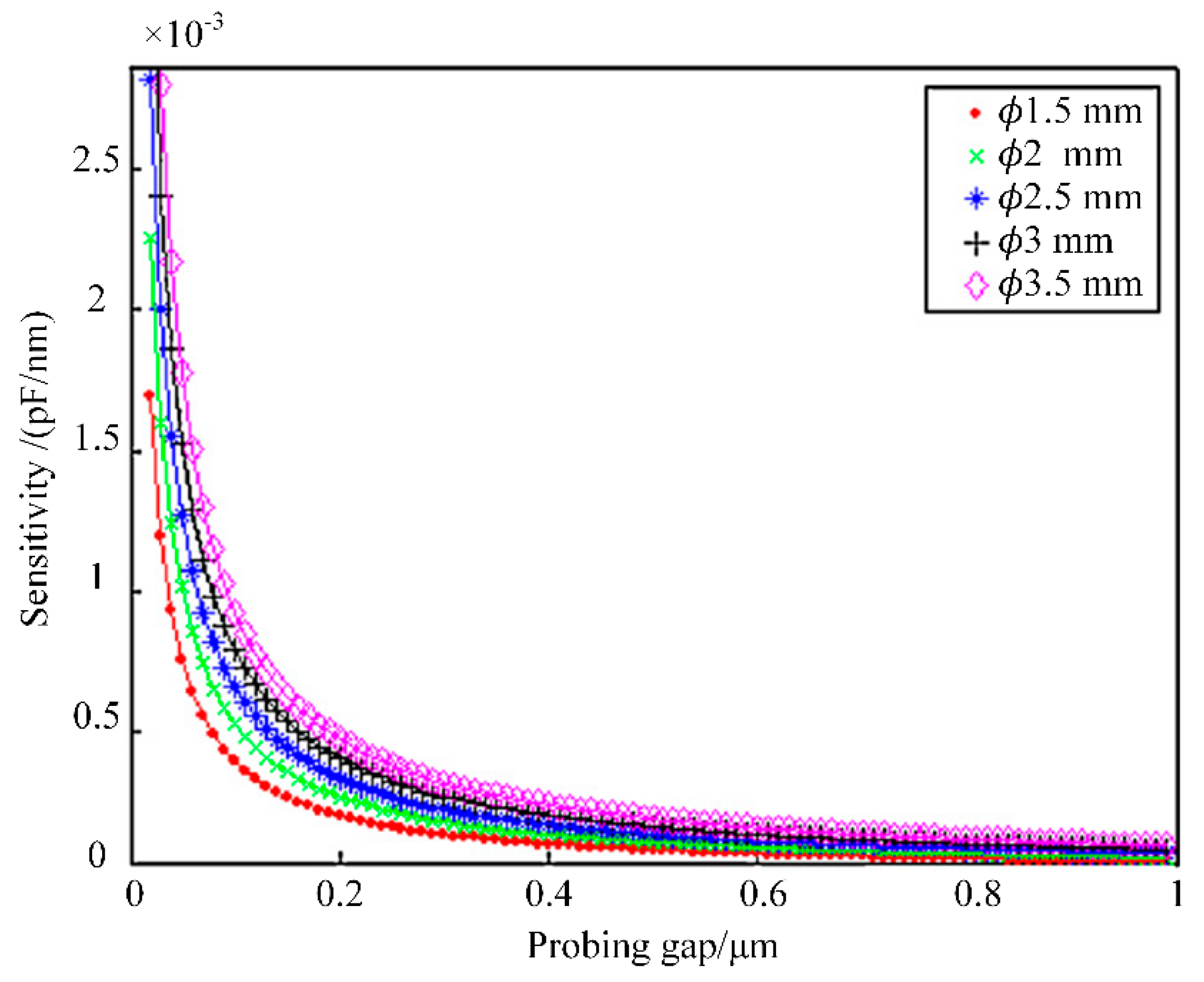
Figure 4 shows the sensitivity characteristics of probing balls of different diameters when a plane was probed using capacitive signal processing techniques. The sensitivity was defined as the quotient of the change of capacitance and the corresponding change of the probing gap. The sensitivity increased with a decreasing probing gap (δ). The sensitivity increased more dramatically when δ was below 0.2 μm. Nanometer resolution could be achieved as a result of these characteristics.

3. Development of the Hole Diameter Measuring Machine

An HDMM was specially developed for ultraprecision diameter measurement of small holes with large depth-to-diameter ratios. Key issues, including machine structural design, the development of the probing sensor, the multi-degree-of-freedom attitude-adjusting worktable, and laser interferometry for macro probe displacement measurement, were subsequently described. The measurement process was optimally planned.

3.1. Structural Design of the Measuring Machine

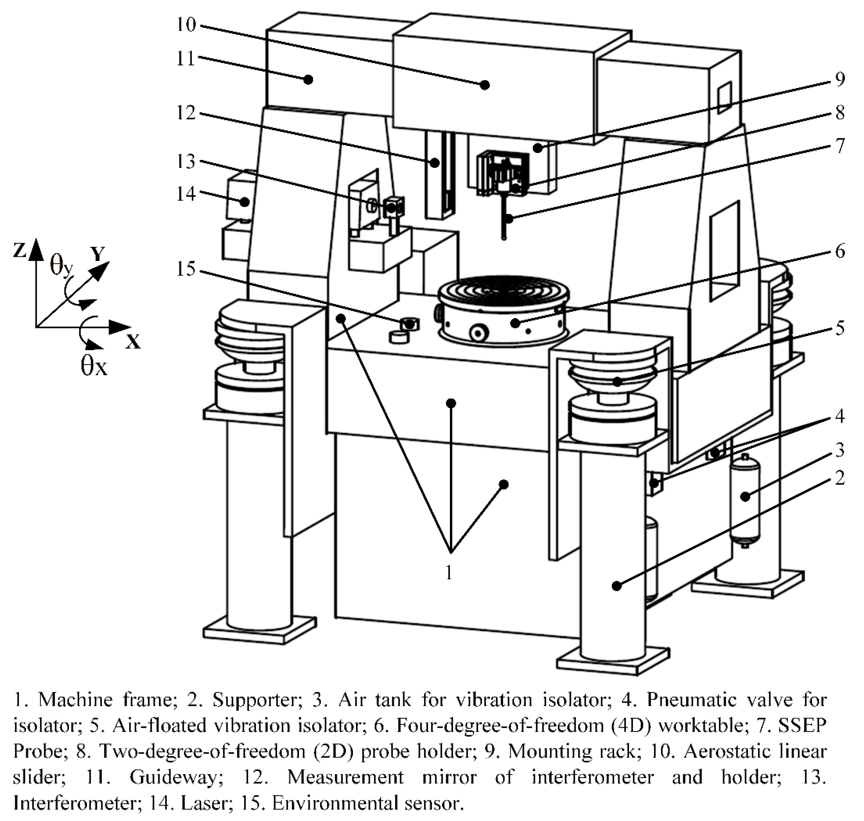
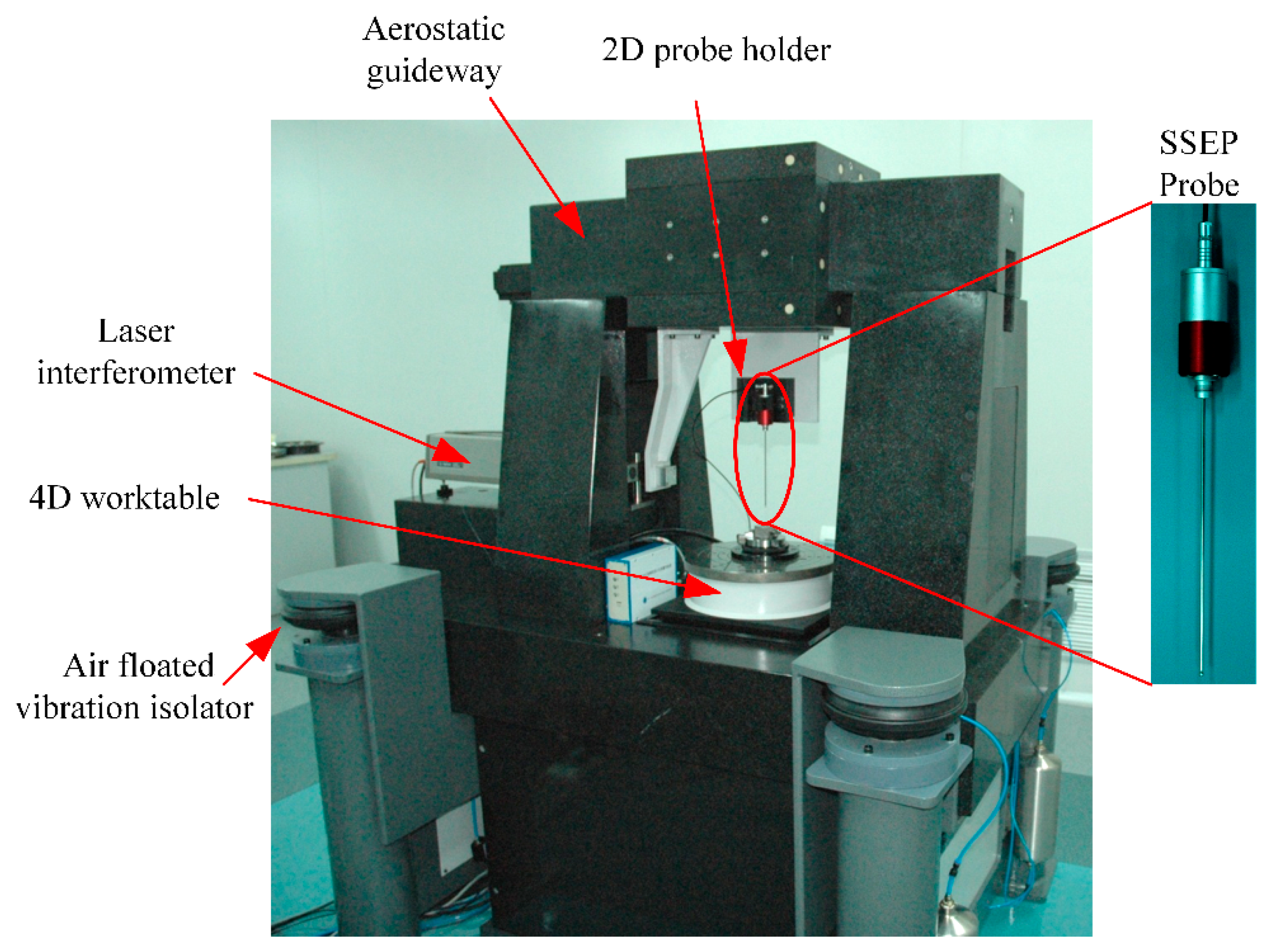
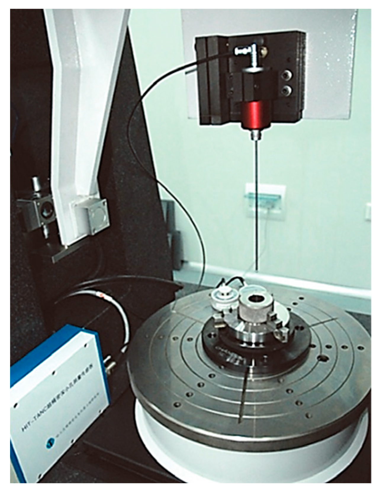
The structure of the HDMM is shown in Figure 5. A photo of the HDMM is shown in Figure 6. The machine had seven degrees of freedom of precision movement and positioning. The probe was mounted on a probe holder with two degrees of freedom (2D), which was mounted on an aerostatic linear slider. The 2D probe holder was used to precisely adjust the axis of the probe stylus to be parallel to the Z axis of the HDMM. The aerostatic linear slider could move horizontally in the X direction, which was also the direction of the measurement line of the hole diameter. The slider stroke in the X direction was 50 mm. A linear glass encoder with a resolution of 5 nm and an accuracy of ~1 μm after calibration was provided for the X slider. A laser interferometer was used to measure the macro displacement of the probe, i.e., l in Equation (1). The part to be measured was mounted on a four-degrees-of-freedom (4D) worktable. The worktable could be controlled to move in the Y and Z directions, as well as to rotate in θx (about the X axis) and θy (about the Y axis) directions. The position and attitude of the hole to be measured could therefore be precisely adjusted with the worktable, which is further described in Section 3.3. The slider in the Z direction had a stroke of 150 mm. A linear glass encoder with a resolution of 5 nm and an accuracy of ~1 μm after calibration was also provided for the Z slider. The tilting angle of the worktable was adjusted with fine thread and servo motors. The tilting angle was evaluated according to pulse counts of the rotary encoders of the motors, and one count corresponded to ~0.005″. The maximum error of the tilting angle adjustment of the worktable was ~0.2″, well meeting the measurement requirement.
The measuring machine was supported by four air-floated vibration isolators. Environmental sensors were used to monitor the worktable temperature, air temperature, and air humidity to allow for compensation of the thermal expansion of the material and change of the air refractive index.

3.2. Development of Probing Sensor

According to theoretical modeling results, when capacitive signal processing techniques are used after constructing certain boundary conditions for the spherical scattering electrical field, the capacitive signal of the probe is on the order of a few pF [17]. As a result, weak capacitive signal processing circuits were designed and a signal modulation and demodulation method was used.
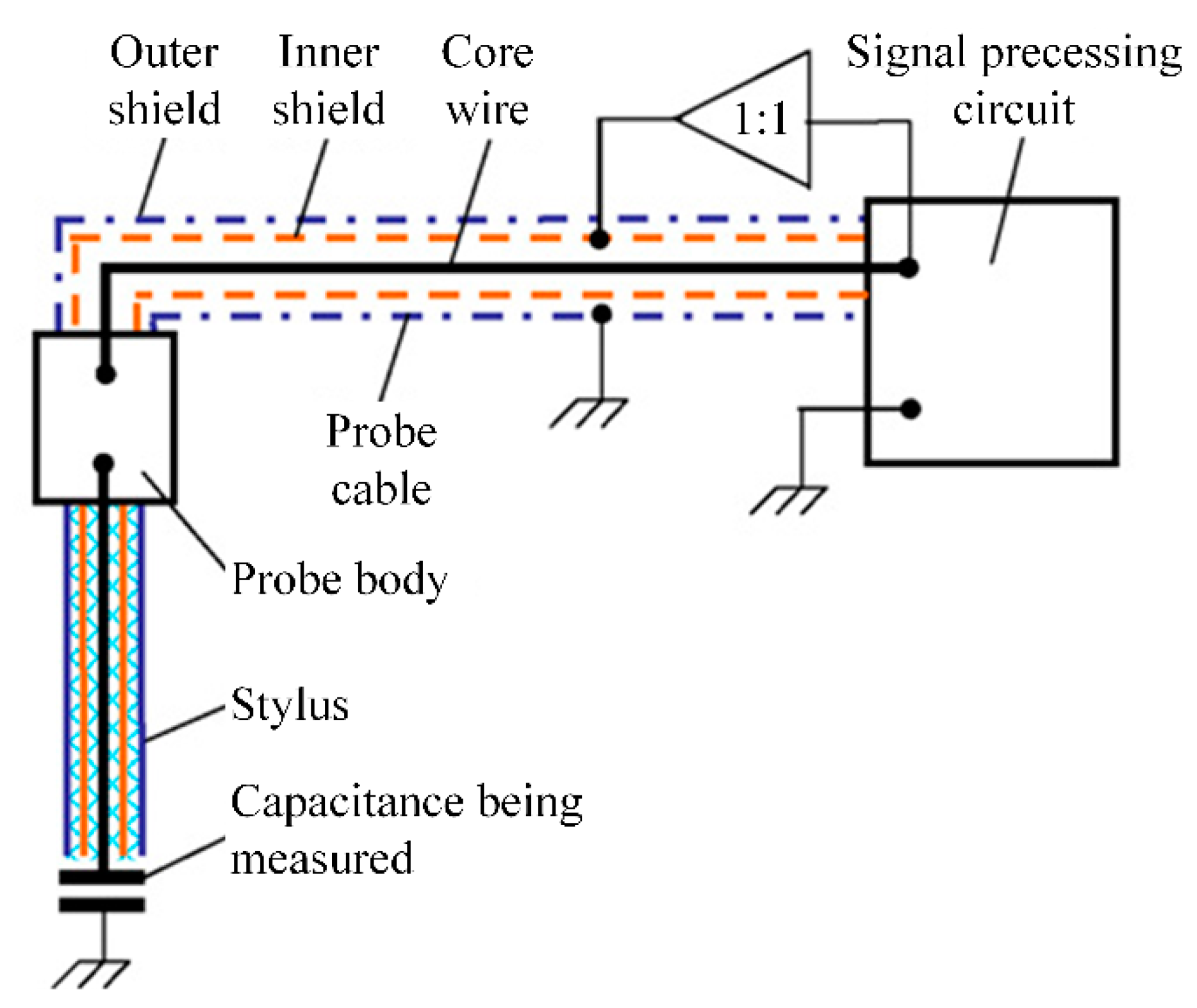
In order to avoid electromagnetic interference and ensure signal quality, a tri-coaxial active shielding structure was used in the SSEP sensor, which consisted of an SSEP probe and signal processing circuits, as shown in Figure 7. The inner shield, outer shield, and the signal conducting core wire of the stylus and probe cable comprised a tri-coaxial structure. The outer shield was grounded to shield off spatial electromagnetic interferences and eliminate the influence of parasitic capacitance. The inner shield was driven by a 1:1 amplifier and kept equipotential with the signal conducting wire to eliminate the influence of parasitic capacitance between them.
A series of SSEP probes, with diameters ranging from ϕ1.5 mm to ϕ3.5 mm and stylus aspect ratios from 20 to 50, were developed. Figure 8 shows an SSEP probe prototype with a ϕ3-mm probing ball and a 150-mm-long stylus. Figure 9 shows the signal processing circuits. Nonlinearity correction, communication, and triggering control during probing was also conducted by the signal processing circuits.

3.3. Four-Degree-of-Freedom Attitude-Adjusting Worktable

Precise and multi-degree-of-freedom adjustment of hole attitude also need to be thoroughly considered to realize ultraprecision measurement of deep and small hole diameters. The hole attitude must be precisely adjusted to make its axis parallel to the Z axis of the HDMM before diameter measurement. This was realized through a 4D attitude-adjusting worktable on which the part to be measured was mounted.
The inclination angles of the hole axis in the θx and θy directions with respect to the Z axis of the HDMM needed to be acquired to provide reference values for adjustment. The principle of determining an inclination angle from the 3D probing capability of the SSEP probe is shown in Figure 10. By successively probing the sidewalls of an upper section and a lower section, l 1 , l 2 , and h could be obtained, and then the inclination angle α could be calculated according to Equation (2).
After acquiring inclination angles α and α′ in two directions, the 4D worktable was rotated by − α and −α′ in respective directions. The process of acquiring inclination angles and adjusting the worktable could be repeated until the inclination angles were smaller than a specified threshold. The experimental results show that two to three adjustments of the worktable are typically sufficient to reduce the inclination angle of the hole axis to a negligible value, thereby satisfying the measurement requirement.
It should be noted that the hole is assumed to be cylindrical here because the holes to be measured in the aviation, aerospace, and automotive industries are mostly cylindrical. Holes with a non-cylindrical shape are rarely seen. Also, because the precision of precisely manufactured holes in the aviation, aerospace, and automotive industries is usually in the micron order, misalignment resulting from differences at two different heights and the corresponding introduced measurement error is very small and can be ignored. Even for a truncated cone-shaped hole, the nominal value of its flank angle relative to its axis can be used to realize precision alignment.
tan α = | l 1 l 2 | h

3.4. Macro Probe Displacement Measurement with Laser Interferometry

According to Equation (1), it is important to accurately obtain the macro displacement of the probe between the two probing points. A laser interferometer with a resolution of 1 nm was designed and integrated into the HDMM. According to calibration results, the relative length measurement error of the interferometer was approximately ±(1.5 × 10⁻⁶). As shown in Figure 5 and Figure 6, the reflecting mirror was fixed on a holder mounted on the aerostatic guideway slider. To reduce the Abbe error, the laser interferometry was designed in such a way that the laser beam was incident on the center of the probing ball, and its direction was carefully adjusted to superpose the moving direction of the slider. In this way, the macro displacement of the probe could be accurately measured using laser interferometry.

3.5. Measurement Process Planning

The measurement process was planned to achieve fully automated hole attitude adjustment and diameter measurement of any cross-sections. The influence of personnel operations could be significantly reduced through automatic adjustment and measurement.
As shown in Figure 11, there were six major steps in the measuring process. First, the upper end face of the hole to be measured was determined with the SSEP probing sensor, and used as the depth reference of the cross-section hole diameter to be measured in the subsequent steps. Then, the hole attitude was finely adjusted using the principles described in Section 3.3. The part was moved vertically in the Z direction until the probing ball center was in the desired cross-section. The probe was then moved in the Y direction to find the inflection point, thus moving the probing ball center to the measurement line of the hole diameter to be measured.
After the adjustment process above, automatic diameter measurement was carried out to obtain l, δ 1 , and δ 2 . Measurements were repeated ten times, and ten measurement results were averaged.

4. Experiments and Measurement Uncertainty Analysis

4.1. Standards and Parts to Be Measured

To verify the performance of the SEPP method and the HDMM, a variety of standards and parts shown in Figure 12 were measured. The two deep and small hole standards were specially designed and used to verify the hole attitude adjustment method, planned measurement process, measurable depth, and depth-to-diameter ratio. The ring gauge standard was calibrated by NIM of China and Physikalisch Technische Bundesanstalt (PTB) of Germany. A tube part from a rocket engine was also measured. To this point, the smallest hole diameter measured with the HDMM was ϕ3 mm, and the maximum hole depth measured was 150 mm.

4.2. Probe Resolution Experiment

Probe resolution experiments were carried out to verify the performance of an SSEP probing sensor. The experiments were conducted in a clean room with a temperature of 20 ± 0.5 °C and humidity of 45 ± 5% RH.
The probe with a ϕ3-mm probing ball shown in Figure 8 was used, and a metal plane part with surface roughness lower than 5 nm was measured. The probe was kept still, while the part was driven close to and away from the probing ball repeatedly with steps of 1 nm, 2 nm, and 3 nm by a piezoelectric stage (PI P-517.3CD). The smallest step that caused a perceptible change in the indication of the probe was defined as the resolution. The piezoelectric stage had a travel of 100 μm, a closed-loop resolution of 1 nm, a repeatability of ±5 nm, and a maximum nonlinearity of 7 nm in the full range. The experimental results are shown in Figure 13. The results indicate that the displacement resolution of the SSEP probe was as small as 1 nm.

4.3. Deep and Small Hole Diameter Measurement Experiment

The experiments were carried out using the specifically designed deep and small hole standards to verify the capability of measurable depth and depth-to-diameter ratio. Experimental results using the #2 standard and the ϕ3-mm probe in Figure 8 are shown in Figure 14. Diameters of six cross-sections at different depths were measured. The interval between adjacent cross-sections was 20 mm, and the maximum depth measured was 120 mm. Figure 14 indicates that the hole in #2 standard was generally conical with a slight trumpet shape at two ends.

4.4. Measurement Accuracy Experiment

Diameter measurement experiments were conducted in the clean room. The ϕ3-mm probe shown in Figure 8 was mounted on the HDMM. To validate the measuring method and the developed HDMM, a calibrated ϕ20-mm ring gauge standard with a depth of 35 mm from Edmunds Gages was used. The standard was mounted on the 4D worktable through a clamper, as shown in Figure 15. The measurement results are shown in Table 1. The average of ten diameter measurement results was 19.99998 mm. The diameter calibration results from NIM (National Institute of Metrology) of China, PTB of Germany, and the results obtained by the authors (HIT-UOI, Harbin Institute of Technology, center of Ultra-precision Optoelectronic Instrument) are compared in Table 2. The uncertainty intervals of all calibrations overlapped, indicating agreement.

4.5. Measurement Uncertainty Analysis

The measurement model for small hole diameters is shown in Equation (1). For simplicity, the measurement model can be expressed as the sum of the macro displacement of the probe l , the probing ball diameter d , and two equal probing gaps δ ( δ 1 and δ 2 are assumed equal) as shown in Equation (3).
D = l + d + 2 δ
The uncertainty model of the diameter measurement is shown in Equation (4):
u D 2 = u l 2 + u d 2 + 4 u δ 2
The sources and estimation of the standard uncertainty components are listed in Table 3. The uncertainty is evaluated according to the Guide to the Estimation of Uncertainty in Calibration of Geometrical Measuring Equipment (JJF 1130-2005). The expanded uncertainty of the diameter measurement result of the ϕ20-mm ring gauge standard is U = 0.2 μm (k = 2).

5. Conclusions

An SSEP method was proposed for ultraprecision diameter measurement of small holes with large depth-to-diameter ratios and a specially designed measuring machine was developed. Experiments were carried out to verify the efficacy of the proposed method and the measurement performance of the machine. The resolution experiment results indicate that a resolution of 1 nm was achieved with a SEEP probe with a ϕ3-mm probing ball and a 150-mm stylus. The hole diameter measurement experiment results indicate that an expanded uncertainty of 0.2 μm (k = 2) was achieved when a standard with a ϕ20-mm nominal diameter was measured. It can be concluded that the proposed SSEP method is an effective solution for ultraprecision diameter measurement of small holes with large depth-to-diameter ratios. Future work will be focused on the application of the HDMM for micro holes with large aspect ratios and other inner structures.

Author Contributions

Conceptualization, J.C.; Methodology, J.C.; Software, Y.L.; Supervision, J.T.; Validation, X.B.; Writing—original draft, X.B.; Writing—review and editing, X.B.

Funding

This research was funded by [National Natural Science Foundation of China] grant number [51675139] and [Fundamental Research Funds for the Central Universities].

Acknowledgments

This research work is supported by the National Natural Science Foundation of China (Grant No. 51675139) and the Fundamental Research Funds for the Central Universities. The authors would like to thank the other members of the research team for their contributions to this study.

Conflicts of Interest

The authors declare no conflict of interest.

References

  1. Bos, E.J.C. Aspects of tactile probing on the micro scale. Precis. Eng.-J. Int. Soc. Precis. Eng. Nanotechnol. 2011, 35, 228–240. [Google Scholar] [CrossRef]
  2. Bauza, M.B.; Woody, S.C.; Woody, B.A.; Smith, S.T. Surface profilometry of high aspect ratio features. Wear 2011, 271, 519–522. [Google Scholar] [CrossRef]
  3. Hansen, H.N.; Carneiro, K.; Haitjema, H.; De Chiffre, L. Dimensional micro and nano metrology. CIRP Ann. Manuf. Technol. 2006, 55, 721–743. [Google Scholar] [CrossRef]
  4. Küng, A.; Meli, F.; Thalmann, R. Ultraprecision micro-cmm using a low force 3d touch probe. Meas. Sci. Technol. 2007, 18, 319. [Google Scholar] [CrossRef]
  5. Takamasu, K.; Chih-Che, K.; Suzuki, A.; Hiraki, M.; Furutani, R.; Ozono, S. Development of pneumatic ball probe for measuring small hole. In Proceedings of the International Conference on Precision Engineering, Taipei, Taiwan, 20–22 November 1997. [Google Scholar]
  6. Tian, G.Y.; Zhao, Z.X.; Baines, R.W.; Corcoran, P. A miniaturised sensor for deep hole diameter measurement. Precis. Eng. 1999, 23, 236–242. [Google Scholar] [CrossRef]
  7. Sun, C.-K.; Wang, X.-B.; Liu, B.; Zheng, Y.-Z. Capacitance sensor measurement method for micro-aperture. Nanotechnol. Precis. Eng. 2006, 2, 103–107. [Google Scholar]
  8. Grandy, D.; Koshy, P.; Klocke, F. Pneumatic non-contact roughness assessment of moving surfaces. CIRP Ann. 2009, 58, 515–518. [Google Scholar] [CrossRef] [Green Version]
  9. Schmitt, R.; Pfeifer, T.; Depiereux, F.; König, N. Novel fiber-optical interferometer with miniaturized probe for in-hole measurements. Optoelectron. Lett. 2008, 4, 140–142. [Google Scholar] [CrossRef]
  10. Zhao, W.; Tan, J.; Qiu, L.; Zou, L. A new laser heterodyne confocal probe for ultraprecision measurement of discontinuous contours. Meas. Sci. Technol. 2005, 16, 497. [Google Scholar] [CrossRef]
  11. Heredia-Ortiz, M.; Patterson, E.A. On the industrial applications of moiré and fringe projection techniques. Strai 2003, 39, 95–100. [Google Scholar] [CrossRef]
  12. Casavola, C.; Pappalettera, G.; Pappalettere, C. Design of a fiber optics fringe projector for 3d reconstruction of dental elements. In Proceedings of the 2014 Third Mediterranean Photonics Conference, Trani, Italy, 7–9 May 2014; pp. 1–3. [Google Scholar]
  13. Muralikrishnan, B.; Stone, J.A.; Stoup, J.R. Fiber deflection probe for small hole metrology. Precis. Eng. 2006, 30, 154–164. [Google Scholar] [CrossRef]
  14. Beomjoon, K.; Takahisa, M.; Tarik, B. The vibroscanning method for the measurement of micro-hole profiles. Meas. Sci. Technol. 1999, 10, 697. [Google Scholar]
  15. Weckenmann, A.; Peggs, G.; Hoffmann, J. Probing systems for dimensional micro- and nano-metrology. Meas. Sci. Technol. 2006, 17, 504. [Google Scholar] [CrossRef]
  16. Tan, J.; Cui, J.; Cui, J. Ultraprecision Non-Contact Three-Dimensional Probing System Based on Spherical Capacitive Plate. U.S. Patent 8,816,702, 26 August 2014. [Google Scholar]
  17. Tan, J.; Cui, J. Ultraprecision 3d probing system based on spherical capacitive plate. Sens. Actuators A Phys. 2010, 159, 1–6. [Google Scholar] [CrossRef]
  18. Bian, X.; Cui, J.; Lu, Y.; Tan, J. Bias electric field distribution analysis based on finite difference method with non-uniform grids for a non-contact tunneling current probe. In 10th International Symposium on Precision Engineering Measurement and Instrumentation; SPIE: Kunming, China, 2018; in press. [Google Scholar]
Figure 1. Schematic diagram of the spherical scattering electrical-field probing (SSEP) method.
Applsci 09 00242 g001
Figure 2. Surface charge density characteristics of a ϕ3-mm probing ball when a conductor plane (yoz plane) is probed.
Applsci 09 00242 g002
Figure 3. Relationship of the surface charge ratio to surface area ratio. (a) Simulation results with different holes (probing gap = 0.2 μm); (b) simulation results with different probing gaps (hole diameter = ϕ12 mm).
Applsci 09 00242 g003
Figure 4. Sensitivity characteristics of probing balls of different diameters.
Applsci 09 00242 g004
Figure 5. Structural design of the hole diameter measuring machine (HDMM). SSEP: spherical scattering electrical-field probing.
Applsci 09 00242 g005
Figure 6. Photo of the HDMM developed. SSEP: spherical scattering electrical-field probing.
Applsci 09 00242 g006
Figure 7. Tri-coaxial active shielding structure of the SSEP probing sensor.
Applsci 09 00242 g007
Figure 8. A SSEP probe prototype.
Applsci 09 00242 g008
Figure 9. Signal processing circuits and box.
Applsci 09 00242 g009
Figure 10. Principle of determining the inclination angle.
Applsci 09 00242 g010
Figure 11. Diameter measurement process.
Applsci 09 00242 g011
Figure 12. Standards and parts.
Applsci 09 00242 g012
Figure 13. Resolution experiment results.
Applsci 09 00242 g013
Figure 14. Diameter measurement results as a function of measured depth.
Applsci 09 00242 g014
Figure 15. Measurement of ϕ20-mm ring gauge standard with the HDMM.
Applsci 09 00242 g015
Table 1. Diameter measurement results of ϕ20-mm ring gauge standard.
Measurement Number12345
Measurement Result/mm19.9999320.0000020.0000120.0000120.00001
Measurement Number678910
Measurement Result/mm19.9999819.9999319.9999519.9999720.00001
Table 2. Comparison of diameter calibration results. PTB: Physikalisch Technische Bundesanstalt; NIM: National Institute of Metrology; HIT-UOI: Harbin Institute of Technology, center of Ultra-precision Optoelectronic Instrument.
LabDiameter Value D (mm)Expand Uncertainty U (μm, k = 2)
PTB20.000000.1
NIM20.000300.5
HIT-UOI19.999980.2
Table 3. Sources and estimation of uncertainty components.
SymbolError Source and TypeEstimation/μm
u l uncertainty introduced by macro displacement measurement with interferometermeasurement repeatability (A 1)0.040
interferometry measurement (B 2)0.002
linearity of aerostatic guideway (B)0.026
u l = 0.048
u d uncertainty introduced by calibration of the probe ball diameterstandard (B)0.031
interferometry measurement (B)0.040
probing error (B)0.036
u d = 0.088
u δ uncertainty introduced by probingprobing repeatability (A)0.040
probing resolution (B)0.003
nonlinearity of probing sensor (B)0.006
indication stability (B)0.003
u δ = 0.041
expanded uncertaintyU = 0.2 μm (k = 2)
1 Type A evaluation of uncertainty; 2 Type B evaluation of uncertainty.

