Article

Continuous-Variable Quantum Key Distribution Robust Against Polarization-Dependent Loss

School of Computer Science and Engineering, Central South University, Changsha 410083, China
*
Author to whom correspondence should be addressed.
Appl. Sci. 2019, 9(18), 3937; https://doi.org/10.3390/app9183937
Submission received: 3 September 2019 / Revised: 17 September 2019 / Accepted: 18 September 2019 / Published: 19 September 2019
(This article belongs to the Special Issue Quantum Communications and Quantum Networks)

Abstract

:
Polarization is one of the physical characteristics of optical waves, and the polarization-division-multiplexing (PDM) scheme has gained much attraction thanks to its capability of achieving high transmission rate. In the PDM-based quantum key distribution (QKD), the key information could be encoded independently by the optical fields E x and E y , where the 2-dimensional modulation and orthogonal polarization multiplexing usually result in two-fold channel capacity. Unfortunately, the non-negligible polarization-dependent loss (PDL) caused by the crystal dichroism in optical devices may result in the signal distortion, leading to an imbalanced optical signal-to-noise ratio. Here, we present a polarization-pairwise coding (PPC) scheme for the PDM-based continuous-variable (CV) QKD systems to overcome the PDL problem. Numerical simulation results indicate that the PDL-induced performance degradation can be mitigated. In addition, the PPC scheme, tailored to be robust against a high level of PDL, offers a suitable solution to improve the performance of the PDM-based CVQKD in terms of the secret key rate and maximal transmission distance.

1. Introduction

Quantum key distribution (QKD) is an important application of quantum technology [1,2]. Continuous-variable (CV) QKD has been explored as an efficient approach to achieve quantum communication [3,4]. It offers a prospect of higher detection efficiency and secret key rate compared with its discrete-variable (DV) counterpart, giving birth to extensive application perspectives [5,6,7,8,9]. Since the representative coherent protocol was proposed it has attracted attention and, hence, become one of the mainstream protocols [10,11,12,13]. This protocol can be linked with the current optical fiber communication system, without the need of additional infrastructure construction and equipment configuration [14,15,16,17].
For the past years, CVQKD has developed towards long-haul and large-capacity transmission, and the channel multiplexing technology is an important approach for establishing practical quantum communication network [18]. In order to improve channel modulation capacity, the elegant technologies—e.g., the positive quadrature phase shift modulation (QPSK) and polarization-division-multiplexing (PDM)—are brought into focus [19]. The latter can double the transmission capacity by using two orthogonal polarizations of a wavelength channel without additional bandwidth resources. For a PDM-coherent optical system, it is important to ensure the orthogonality of two related channels as much as possible. Unfortunately, due to the influence of polarization-dependent loss (PDL) such as multiplexers, splitters, silicon photonics modulators, etc., it will be one of the challenging problems for the PDM-based CVQKD system [20]. The PDL is caused by the crystal dichroism in optical devices. It describes the maximum transmission difference of polarization states, which gives birth to orthogonal polarizations being attenuated in varying degrees. What is more, it will cause an imbalanced signal-to-noise ratio (SNR) between polarizations. However, it still remains an unresolved problem due to its nonunitary nature [21,22,23,24]. An accumulated PDL can be observed after transmission [25]. It would cause increased signal distortion, and consequently obtain a higher error rate, worse secret key rate and transmission distance in the system.
In order to mitigate the effect of PDL on the PDM-based system, a polarization-pairwise coding (PPC) scheme is proposed to enhance the practical performance. The PPC scheme shows the enhanced performance, which is compared with the Walsh–Hadamard transform that maximizes the coordinate diversity, and its decoder is much simpler than that of the Golden or Silver code [26,27,28]. Based on the PPC scheme, we can similarly achieve the PDL mitigation in the CVQKD system, where the CV-polarization is used for quantum communication.
This paper is organized as follows. In Section 2, we suggest the four-state PDM-based CVQKD protocol with the discrete modulation. In Section 3, we show the influence of PDL on the system and demonstrate the need of mitigating it. In Section 4, we propose the PPC scheme for the system, and present details of coding procedure. In Section 5, we perform a specific proof-of-principle simulation of the proposed scheme in the system with security results. Finally the conclusions are drawn in Section 6.

2. The PDM-Based CVQKD Scheme

We consider a discretely modulated CVQKD protocol since it is suitable for long-distance transmission [29]. In order to increase the transmission capacity, the PDM scheme can be applied in modulation. In Figure 1a, we show the schematic diagram in the PDM-based CVQKD system. At Alice’s side, the light beam from laser is encoded and modulated, resulting in PDM signals. We will elaborate on this specific process after we put forward the coding scheme. A polarization beam splitter is used for splitting the signals into two polarizations, and the two polarizations are recombined by using a polarization beam combiner after modulation. At destination, Bob demultiplexes the incoming signals and measures one of them with homodyne detector. The transmission of two polarizations with PDL is shown in Figure 1b. There is a component projection on the corresponding channel, leading to the crosstalk between channels.
The transmission of signals in optical fiber through a single beam is involved in the PDM-based CVQKD system, which can be described as follows:
Step 1: Alice randomly picks up a random variable x k { 1 , 2 , 3 , 4 } and encodes a coherent state | α k { | α 1 = | r + r i , | α 2 = | r + r i , | α 3 = | r r i , | α 4 = | r r i } , where r is a positive real number depending on Bob’s signal-to-noise ratio (SNR) and k denotes the index of time slot—and sends it through a quantum channel with loss and noise interference. After perfect PDM, there will be two mutually delayed polarization signal lights from the same beam of light.
Step 2: Alice sends the prepared coherent states through a quantum channel to Bob. Bob receives quantum states from two polarizations separated by a PBS. Bob’s detection process of quantum states on two channels is similar. Then, Bob randomly selects the measurement basis through the decoding system and measures the components. Through the classical authentication channel, the selected measurement basis is published. Alice and Bob will discard the wrong measurement basis.
Step 3: Bob identifies and extracts effective coherent state signals and derives the phase of the coherent state including serial information. He performs the demodulating and decoding operations, and finally establishes a shared key with Alice after the error correction and privacy amplification processing.

3. The PDL-Involved CVQKD System

The noise of CVQKD system can be divided into two kinds. One is the scattered noise caused by channel loss, which is incompressible. The other is the excess noise introduced by optical devices, electrical noise of circuits, etc., which can be compressed by improved designs as much as possible. In the PDM-based CVQKD system, several optical characteristics such as chromatic dispersion, polarization mode dispersion, and even nonlinear distortions would cause excess noise, but can be compensated for achieving high-tolerance [30,31]. However, it is difficult to realize the perfect compensation for PDL due to its nonunitary nature. We will analyze the source of PDL and the effect of PDL on the secret key rate in the PDM-based CVQKD system, and find a way to solve it.

3.1. Polarization-Dependent Loss in Communication

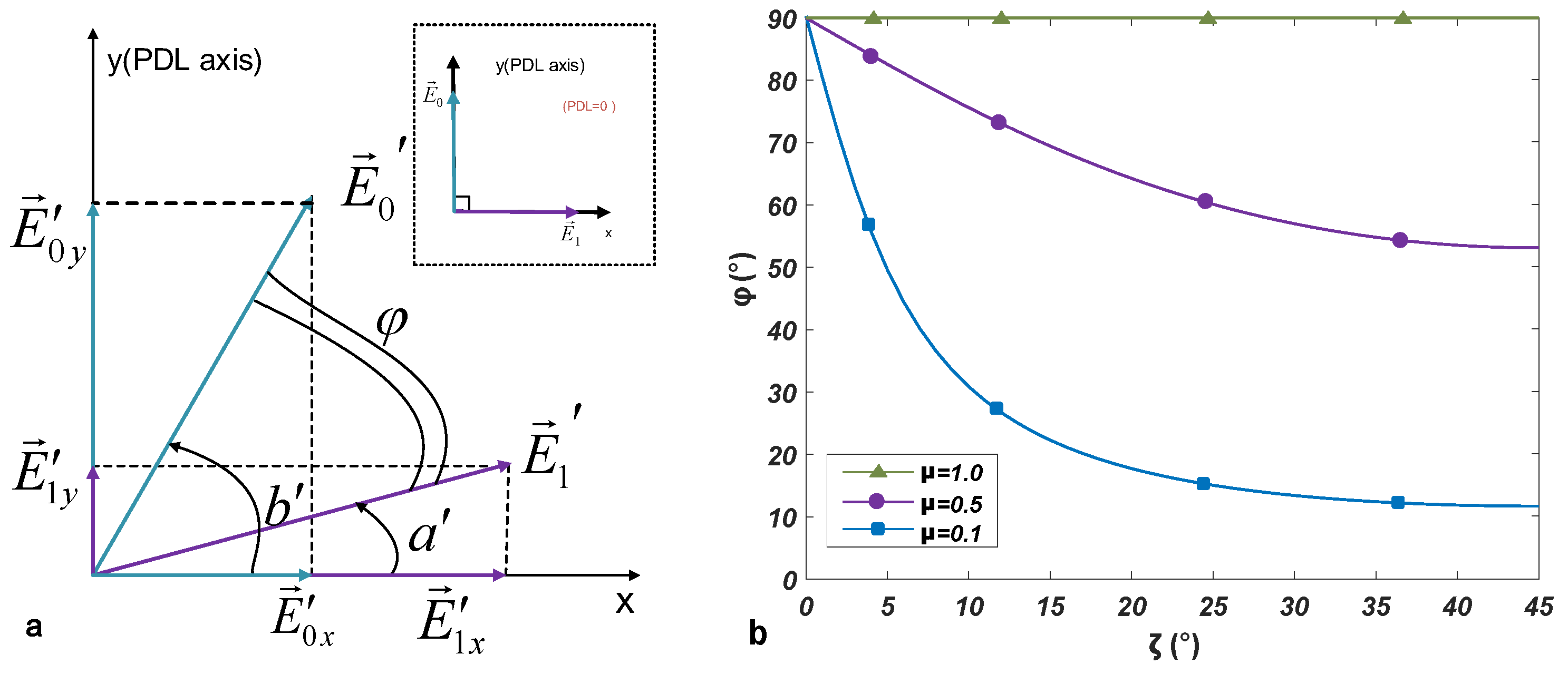
In most of birefringent crystals inside, the polarized light absorptions of two orthogonal polarizations are the same. Nevertheless, some of the crystals will have different absorbing ability due to their dichroism. Dichroism is a phenomenon associated with polarization states of input light, which is generated within a crystal. And then it produces the PDL that interfere with the system’s performance. For the single-mode optical fiber containing SiO 2 , the effect of PDL is very weak. But in optical devices, such as multiplexers, splitters, etc., it should not be ignored since it may make optical signals undergo different losses in different polarization directions. PDL describes the maximum and minimum value of the transmission of light through a device or communication system, in the presence of polarization. It can be expressed as the ratio of power, i.e., 10 log ( γ m a x / γ m i n ( d B ) , in consequence, where γ is the optical power taken over by the entire polarization state. The output light power will vary between the maximum and minimum values due to the influence of different polarization states. Thus, PDL could be viewed as polarization selective fading. The impact on system performance is the increased signal distortion [21,32]. Figure 2a shows that PDL causes the destruction of orthogonality of the PDM-based system, where two polarizations lose their orthogonality after transmission with the different loss in their polarization direction.
As the signal polarization is not limited to the optical fiber network, the insertion loss of the device varies with the polarization state. This effect increases uncontrollably along the transmission link and has an impact on transmission quality. PDL of individual devices can cause large power fluctuations in the system, thus raising the error rate and causing network failure. PDL may be the main source of pulse distortion and diffusion. The PDL-distributed model is shown in Figure 2b. There are some PDL emulators (PDLE), and the amplified spontaneous emission (ASE) noise depolarized by PDL is loaded, both of which are distributed along a link [33]. Usually, several polarization controllers are inserted before the PDLE to obtain the PDL penalty at a special polarization.

3.2. The Effect of PDL on Orthogonal Components

Due to the effect of PDL, an angle between two channels decreases with the increasing loss. Therefore, there is a component projection on the corresponding channel, eventually leading to the crosstalk between channels. Figure 3a reveals the effect on components of the electric field. The right panel shows the state of the electric field vectors before entering the component with PDL, while the left panel shows these vectors after propagating through the component with PDL.
When two polarizations enter the optical devices, a and b are the angles of the electric field with the corresponding outputs a and b . For τ { a , b } and τ { a , b } , we have [25]
τ = tan 1 ( tan ( τ ) × 10 | PDL | 20 ) ,
where 0 a 90 and 0 b 90 . The relative angle of two nonorthogonal polarizations is given by φ = | a b | , which experiences a periodic variation dependent on a and b.
Let μ be the relative PDL factor between two polarizations and ζ is the incident angle, which is the angle between one of these channels and the X-axis, then, we have
φ = arccos 1 μ 2 μ 4 + μ 2 ( tan 2 ζ + cot 2 ζ ) + 1 .
With the variable relative loss factor μ , the orthogonality between two originally orthogonal channels may be lost, where μ { 0.1 , 0.5 , 1.0 } . As shown in Figure 3b, for the decreased μ , the orthogonality becomes worse.

3.3. The PDL-Involved CVQKD System

The quantum state received at Bob’s side can be denoted by the quadratures (X,P) which satisfy
X = η T ( X A + δ X c ) + δ X A , P = η T ( P A + δ P c ) + δ P A ,
where X A and P A are the modulated values with variance X A 2 = P A 2 = V A , and δ X A ( δ P A ) and δ X c ( δ P c ) are originated from the shot noise and channel excess noise, which satisfy δ X A 2 = δ P A 2 = 1 and δ X c 2 = δ P c 2 = ε c in shot noise units, respectively.
Here, we show the derivation of the excess noise due to the effect of PDL. Under the perfect detection, we denote the quadratures of the output mode of quantum channel as ( X t , P t ) . The quadratures without phase compensation can be expressed as
X B = X t + X p d l , P B = P t + P d p l ,
where X d p l , P p d l are the added quadratures arising from the phase error ϕ due to lack of orthogonality, which satisfy X p d l = | α | s i n ϕ and P p d l = | α | c o s ϕ , and α is the parameter of coherent states. It can be regarded as a phase shift operation U ( δ ϕ ) = e x p ( i δ ϕ a a ) on Bob’s measurement results, and δ ϕ follows a probability of p ( δ ϕ ) .

4. Polarization-Pairwise Coding Scheme

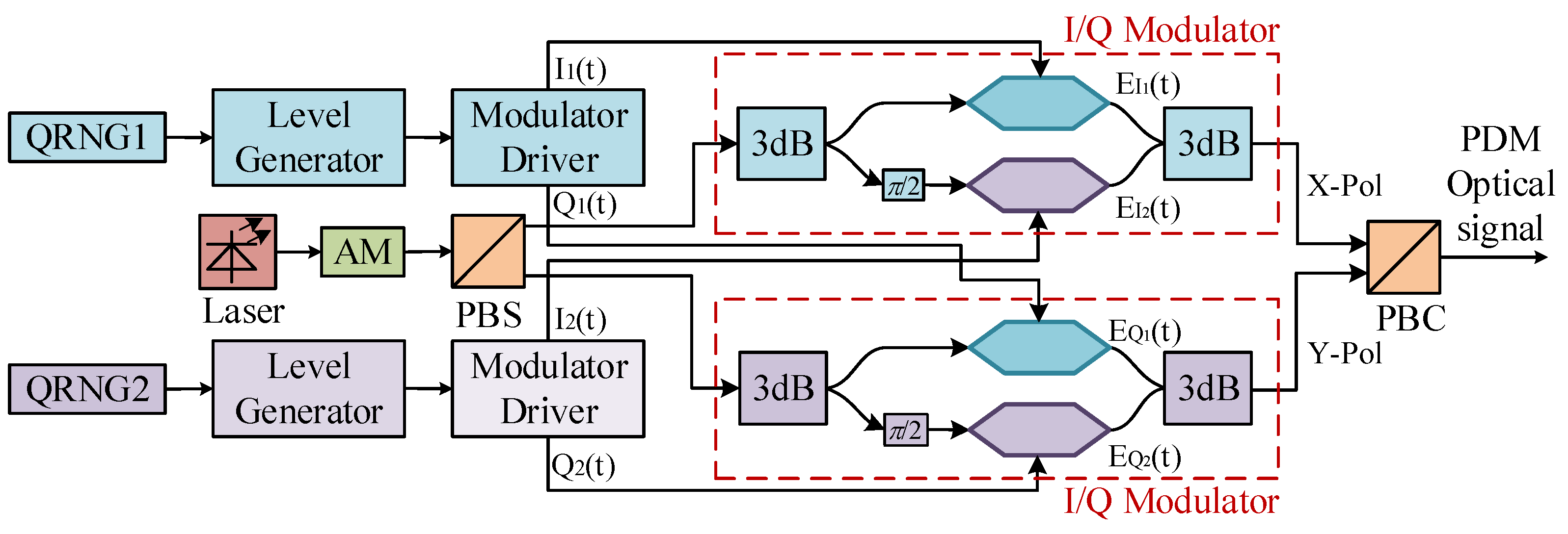
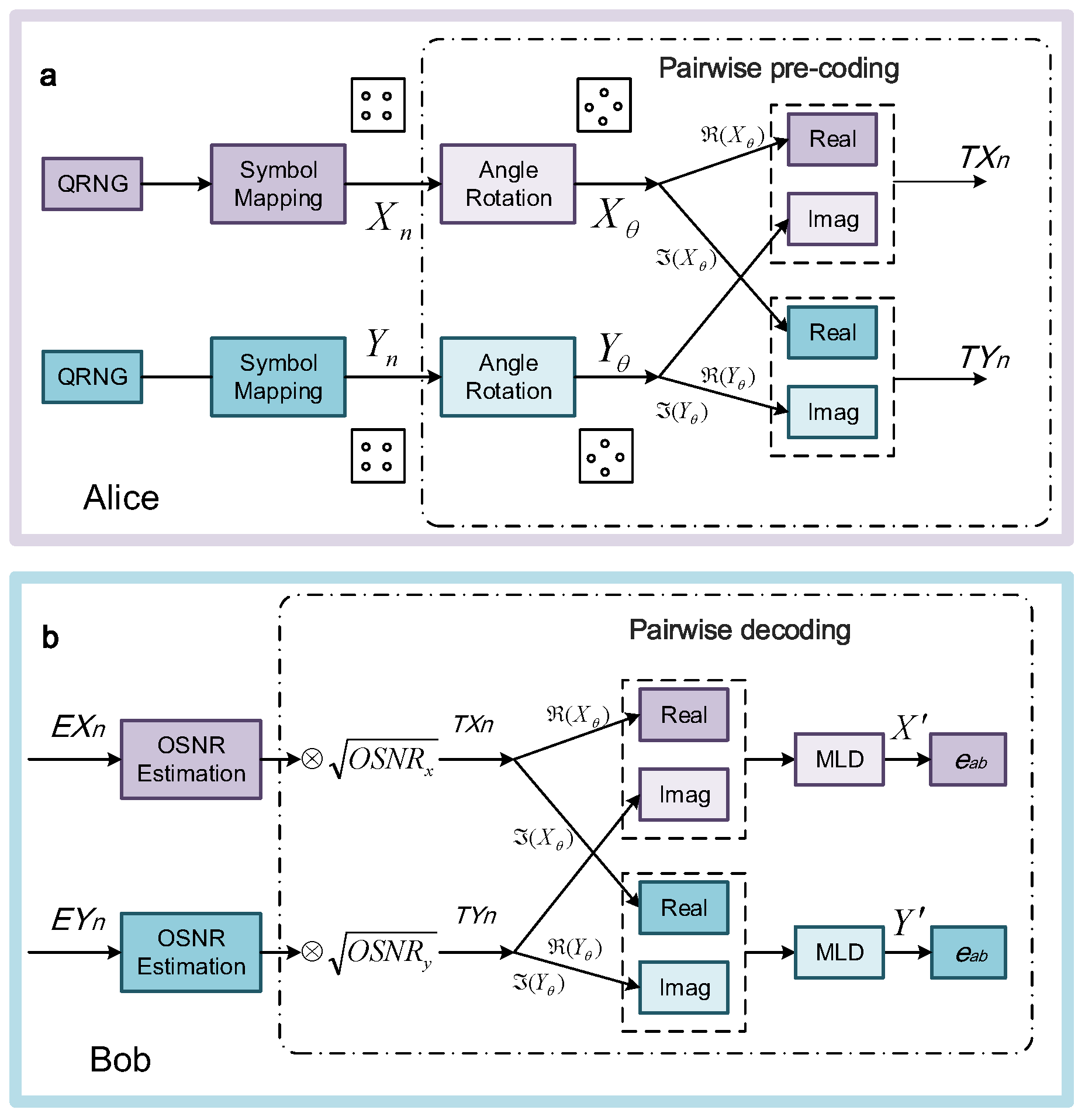
On account of the polarization states whose relative orientations are random and time dependent, the overall instantaneous PDL varies randomly, both in frequency and in time. As a result, it is a corresponding randomization of the received optical signal noise ratio (OSNR). In what follows, we propose a PPC scheme to mitigate the involved PDL, leading to the increased secret key rate of the PDM-based CVQKD system. As shown in Figure 4, The continuous light emitted by the light source is divided into two groups of light carriers with mutually orthogonal polarization through the polarization splitter. Then, the random code of quantum random number generator (QRNG) is modulated into the corresponding driving signal through the level generator and modulator driver. Two Stokes parameter encoders are the key to the realization of phase modulators in each polarization direction. Finally, the optical signals of these two groups of orthogonal polarization are synthesized into one group using PBC, so as to obtain the optical signals. As shown in Figure 5a, when interleaving the real (I) and imaginary (Q) components of both polarizations, only the I or Q of each polarization suffers the worse SNR. Whereas the other signal component has a better SNR, resulting in the improved performance of both polarizations. The PPC scheme is used for improving the CVQKD system without encoding processing in a wide range of worst cases of PDL.
The polarization-pairwise pre-coding scheme is shown in Figure 5. Two polarizations are mapped to quadrature amplitude modulation (QAM) symbols X n = X 0 + P 0 j and Y n = X 1 + P 1 j , respectively. After a constant phase shift, θ , is applied to the related symbols, we obtain X θ , n and Y θ , n , respectively. The optimal rotation angle, θ opt , can be derived analytically for QPSK [26]:
θ o p t = π / 4 , λ 3 tan 1 [ ( λ 1 ) ( λ 1 ) 2 λ ] , λ > 3 ,
where λ = SNR defines the OSNR difference induced by PDL between two polarizations by SNR = OSNR good / OSNR bad , and this rotation angle is used for minimizing the error rate e a b for a given SNR between two polarizations. After the angular rotation, I/Q component interleaving is used for generating signals for two polarizations. The processing can also be described as
T X n = ( X θ ) + ( Y θ ) = X C 0 cos θ P C 0 sin θ + ( X C 1 cos θ P C 1 sin θ ) j , T Y n = ( X θ ) + ( Y θ ) = X C 0 sin θ P C 0 cos θ + ( X C 1 sin θ P C 1 cos θ ) j ,
where ℜ and ℑ denote the I and Q parts of signals, respectively.
Figure 4a indicates the PPC-based CVQKD system with PDM-QPSK for the rotation angle θ o p t = 45 . The I/Q interleaving and angular rotation can be rewritten as
( T X n ) ( T X n ) ( T Y n ) ( T Y n ) = cos θ sin θ sin θ cos θ X C 0 X C 1 P C 0 P C 1 .
We note that the above-derived transform matrix is orthogonal, and, hence, such a coding scheme will not involve extra sensitivity penalty in comparison to conventional QAM modulation without PDL. When the PDL is present, intuitively, after receiver I/Q deinterleaving, the SNR between two polarizations is converted into the SNR imbalance between the I and Q components of two polarizations. Then, the angular rotation can maximize the system performance and the optimal angle is 45 , which is derived on the basis of the minimum-error-rate search. The trade-off for practical implementations has been considered in pertinent literature [26].
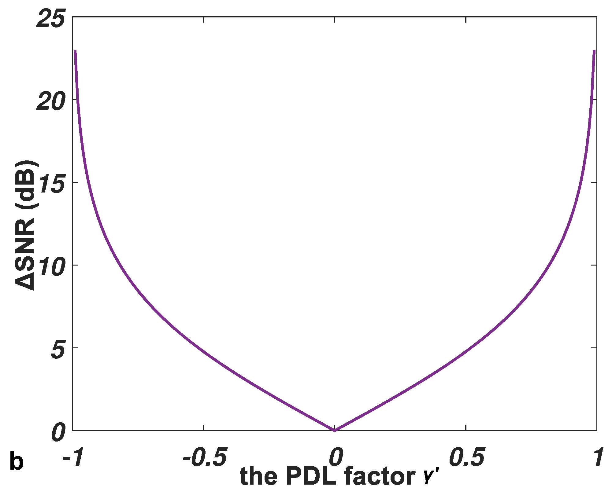
In this scheme, the total SNR is given by Appendix B and the average symbol power of QPSK modulation is 2. Then, the SNR between two polarizations is derived as SNR d B = | 10 log 10 ( 1 + γ 1 γ ) | , where γ is the power factor with γ ( 1 , 1 ) , as shown in Figure 6. Practically, SNR has a random distribution [34]. With the total PDL value L, the lowest and highest possible SNRs are 0 and L, corresponding to the best and worst PDLs, respectively. In the following, we focus on the effect of SNR on system performance. The performance improvement with SNR > 0 can be regarded as an increased tolerance of PDL.
At the receiver, we implement the signal processing, which includes correction, clock recovery, channel compensation, and carrier recovery. The equalized pairwise symbols E q x / E q y are decoded, as shown in Figure 4b. More details are described in Appendix A.

5. Performance Analysis

The four-state protocol has higher data reconciliation efficiency, and thus can be used for lengthening the transmission distance of the CVQKD system [35,36]. Alice sends a random coherent state | α k = | α exp [ i ( 2 k + 1 ) / 4 ] , k { 0 , 1 , 2 , 3 } , to Bob, where α is a real number that can be optimized to maximize the security code rate. In what follows, we show the secure communication code rate of the four-state protocol.
In order to facilitate the security analysis, it is often used to consider the equivalent preparation-measurement scheme. Due to the nonideal modulation in the preparation-measurement scheme and the noise of the light source, the two-mode entangled state produced by Alice is not a pure coherent state, but a mixed state with mixed noise. Due to the symmetry, it is assumed that the mixed state has the same noise as the input of the X component and the P component. The noise will not be used by Eve and can be introduced as a neutral Charlie. Considering the existence of the neutral Charlie, the equivalent entanglement scheme of the case becomes the tripartite subsystems, involving Alice, Bob, and Charlie, which constitutes a pure entangled state.
Assuming the attacker is strong enough, we can replace the actual channel between Alice and Bob with a perfect channel and pure the state ρ A B C . So, the total system | ψ A B E C is a pure state. If Eve can use the state in Charlie s hand, she can get more information. Therefore, the lowest minimum of the security key rate can be obtained.
K = β I ( a : b ) χ ( b : E C ) ,
where β is the key extraction efficiency and I ( a : b ) is the mutual information between Alice and Bob. For the binary symmetric system, I ( a : b ) can be completely decided by the SNR of Bob [37] (more details in Appendix B):
I a : b = 1 h ( e a b ) ,
where h ( p ) = p log 2 ( p ) ( 1 p ) log 2 ( 1 p ) is the binary entropy function and
e a b = 1 1 2 π SNR e x 2 2 d x .
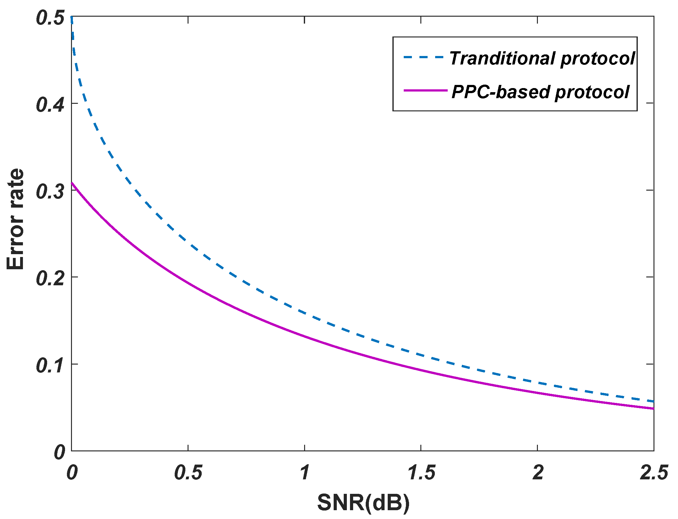
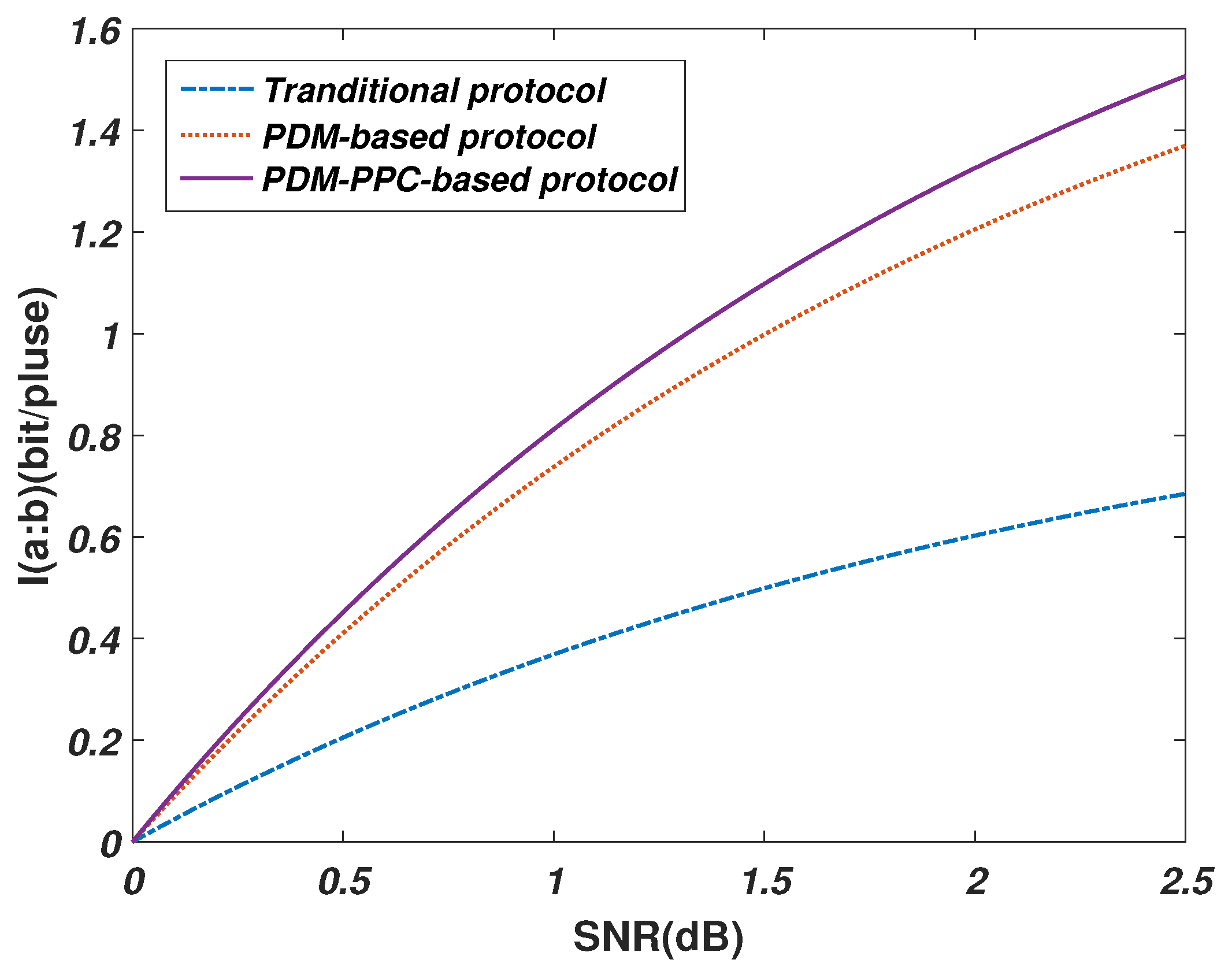
Combining with the above-mentioned PPC scheme, we can obtain the decreased error rate, as shown in Figure 7, where the dashed line shows the transitional four-state protocol and the solid line indicates the PPC-based protocol. The error rate changes with SNR for S N R = 3 d B . It can be observed that the pairwise coded signals achieve a lower error rate to the same SNR extent. In Figure 8, we show the relationship between SNR and I ( a : b ) for four different four-state protocols. The blue line represents the traditional protocol, where we use the most basic four-state protocol. The orange line shows the PDM-based protocol, the amount of I ( a : b ) has nearly doubled. The purple line represents the PDM-PPC-based protocol, where we use PPC scheme on the basis of PDM-based protocol. Under the same SNR, the PDM-PPC-based protocol can obtain the maximum I ( a : b ) . Subsequently, the Holevo boundary χ b : E C is defined as
χ b : E C = S ( ρ E C ) p ( b ) S ρ E C b d b .
Before Bob’s measurement, the state | ψ A B E C is a pure state, resulting in S ( ρ E C ) = S ( ρ A B ) . After Bob s measurement, the state ρ A E C collapses into the form of the | ψ A E C b , which is still a pure state. Therefore, we have S ( ρ E C b ) = S ( ρ A b ) . In addition, because the value of S ( ρ A b ) is independent of b, we can achieve
p ( b ) S ρ E C b d b = p ( b ) S ρ A b d b = S ( ρ A b ) .
Consequently, the lowest minimum of the secret key rate can be calculated as
K = β I ( a : b ) S ( ρ A B ) + S ( ρ A b ) .
Assume that the channel transmittance between Alice and Bob is T 0 and the excess noise is ε 0 . When Alice sends ρ B 0 to Bob, it evolves to be ρ B , and the covariance matrix γ A B of the ρ A B is derived as
γ A B = ( V M + 1 ) I T 0 Z σ z T 0 Z σ z [ T 0 ( V M + ε 0 + δ ε ) + 1 ] I ,
where V M = 2 α 2 is the modulation variance of Alice, I is the identity matrix, Z is the correlation function, source noise is δ ε , and σ z = d i a g ( 1 , 1 ) . The covariance matrix of the output of the state ρ A B after the phase shift operation U ( δ ϕ ) is then derived as
γ δ ϕ = ( V M + 1 ) I Υ Υ [ T 0 ( V M + ε 0 + δ ε ) + 1 ] I ,
where
Υ = T 0 Z c o s δ ϕ T 0 Z s i n δ ϕ T 0 Z s i n δ ϕ T 0 Z c o s δ ϕ .
Then, the state affected by the phase noise is a classical mixture of states with random phase shifts [7]
ρ A B = ( I A U B ( δ ϕ ) ) ρ A B ( I A U B ( δ ϕ ) ) p ( δ ϕ ) d δ ϕ ,
which corresponds to the covariance matrix
γ A B = ( V M + 1 ) I k T 0 Z σ z k T 0 Z σ z [ T 0 ( V M + ε 0 + δ ε ) + 1 ] I ,
where we assumed that the distribution δ ϕ is symmetric. More specifically, δ ϕ satisfies p ( δ ϕ ) s i n δ ϕ d δ ϕ = 0 and k = ( p ( δ ϕ ) c o s δ ϕ d δ ϕ ) 2 = ( E [ c o s δ ϕ ] ) 2 , where E [ X ] denotes the expectation of the random variable X. Therefore, the equivalent transmittance T 0 k and the excess noise ε 0 k of quantum channel after PPC scheme can be expressed as
T 0 k = k T 0 , ε 0 k = [ ε 0 + ( 1 k ) V M ] / k .
Subsequently, the excess noise ε p d l due to lack of orthogonality is given by
ε p d l = ε 0 k ε 0 = ( 1 k ) ( ε 0 + V M ) / k .
According to the optimality of Gaussian attacks, when the covariance matrix is equal, ρ A B is the Gaussian state, leading to the minimum K. For the Gaussian modulation protocol, when the channel transmittance is T and the excess noise is ε , the mixed state covariance matrix of Alice and Bob is given by
γ A B G = ( V M + 1 ) I k T 0 Z E P R σ z k T 0 Z E P R σ z [ T 0 ( V M + ε ) + 1 ] I .
To make γ A B G = γ A B , we obtain
T = k T 0 Z 2 Z E P R 2 , ε = Z E P R 2 Z 2 ( V M + ε 0 + δ ε ) V M .
Therefore, for the discrete modulation scheme with a modulation variance V M , source noise δ ε , channel transmittance T 0 , and excess noise ε 0 , the lowest minimum of the secret key rate can be obtained by the secret key rate of the Gaussian modulation scheme. The transmittance T and excess noise ε of the equivalent Gaussian modulation scheme are derived by (15). Combining with (6), the secret key rate can be obtained. And the main parameters of the CVQKD protocol in the security analysis are shown in Table 1.
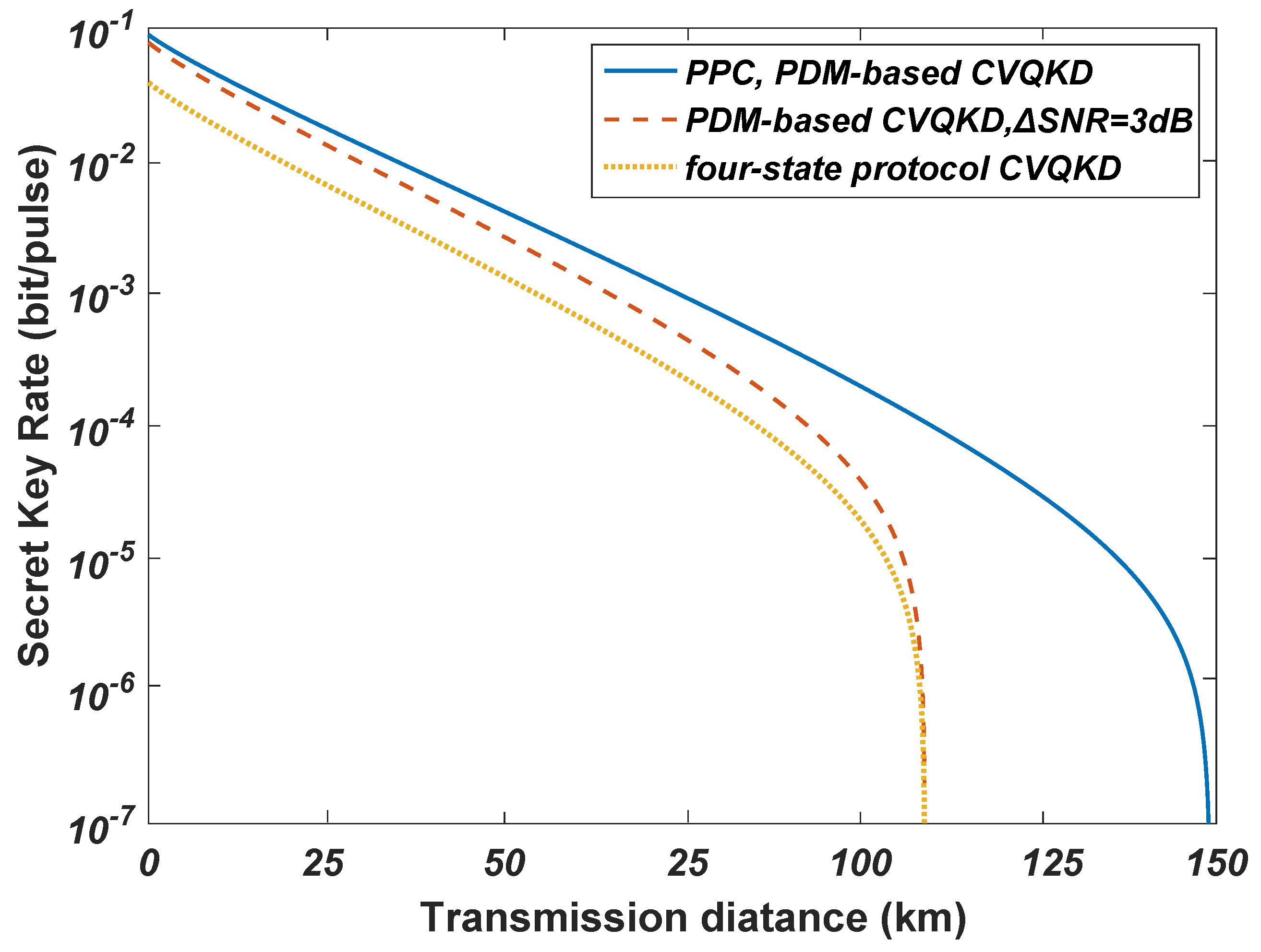
In Figure 9, we demonstrate the secret key rate as a function of modulation variance V M or excess noise ε with transmission distance d = 100 k m , ε { 0.003 , 0.005 , 0.008 , 0.01 } . We can achieve the maximum secret key rate for V M = 0 . 35 in condition of the variational excess noise. In Figure 10, we show the secret key rate as a function of transmission distance, where the dotted line represents the original four-state protocol, the dashed line denotes the PDM-based scheme with discrete modulation, and the solid line is the PDM-based scheme of the four-state protocol with PPC. We find that the secret key rate of the multiplexing scheme is two times higher than that of the conventional four-state protocol. Using the PPC scheme, we can improve the performance of the PDM-based CVQKD system compared with the other schemes.

6. Conclusions

We have proposed a PDM-based CVQKD system over the optical fiber channel, where the key information could be encoded independently by the optical fields E x and E y . By applying the PDM scheme in the system, the 2-dimensional modulation and polarization multiplexing achieve two-fold channel capacity without the need of additional bandwidth resources. Nevertheless, the crosstalk induced by the PDL of each polarization causes the signal distortion, leading to an imbalanced optical signal-to-noise ratio for two polarizations. In order to mitigate the performance decrease, we adopt an improved PPC scheme to overcome the PDL problem. The theoretical analysis shows the performance of the scheme and demonstrates its availability in the system. By selecting the original information symbols and interleaving the X and P components between two polarizations of a given channel, the decoded signals of two polarizations can achieve a lower error rate. In addition, the numerical simulation results indicate that the required SNR is lower than that of the uncoded method when the same error level is reached in the PPC scheme. Besides, the proposed method enhances the overall system performance and is robust against a wide range of PDL without any coding overhead. It reduces the PDL-induced error rate, and thereby increases the secret key rate of the PDM-based CVQKD system.

Author Contributions

Conceptualization, Y.G. and M.C.; writing—original draft, Y.G. and M.C.; writing—review and editing, D.H.

Funding

This work was supported by the National Natural Science Foundation of China (Grant Nos. 61572529, 61871407, 61801522).

Conflicts of Interest

The authors declare no conflict of interest.

Appendix A. The Calculation of BER

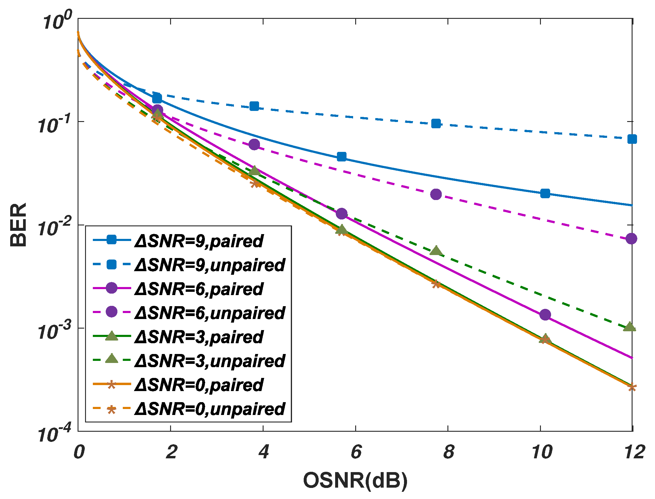
First of all, the SNR estimation is applied to each polarization by using the statistical moments method [38]. In order to calculate, the total SNR is supposed to be 1 / σ 2 and the average symbol power of QPSK modulation is 2. Subsequently, we rescale the equalized signals differently according to the SNR of two polarizations. Particularly, the SNR varies due to the statistical PDL, and therefore the SNR estimation and rescaling should be updated periodically. The I/Q components are then deinterleaved, and the yielded I/Q parts suffer different noise levels. Subsequently, we apply the maximum likelihood detection (MLD) method to symbol decision:
X = arg min c k { | X θ D k | 2 } , Y = arg min c k { | Y θ D k | 2 } , D k = ( C k · e i θ ) · SNR x + j ( C k · e i θ ) · SNR y ,
where C k is the constellation alphabet, i.e., [ 1 + j 1 j 1 + 1 j 1 1 j ] for QPSK modulation, and D k are the rotated and rescaled constellation points. The decisions are finally used for BER calculation. Then, the BER of optical pairwise-coded signals can be written as
BER paired = 0.5 ( 1 + erf ( 1 2 σ ) ) + 0.125 ( 1 + erf ( 1 + η σ ) ) + 0.125 ( 1 + erf ( 1 η σ ) ) .
Compared with the unpaired coding scheme, the average BER can be approximated to
BER unpaired = 0.25 ( 1 erf ( 1 η 2 σ 2 ) ) + 0.25 ( 1 erf ( 1 + η 2 σ 2 ) ) .
In Figure A1, we demonstrate the single-channel OSNR versus. SNR for the rotation angle 45 , where interleaving and deinterleaving the I/Q components are performed at the transmitter and receiver, respectively. With the increased SNR between two polarizations, the PPC scheme increases the performance of the system in terms of BER compared with the unpaired signals. For SNR = 0 , there is no penalty, and the performance is the same as that of unpaired signals. Whereas for SNR = 3/6/9 dB, we find the pairwise coded signals require the lower SNR to achieve BER to the same extent.
Figure A1. The resulting BER of single-channel for △SNR { 0 , 3 , 6 , 9 } dB.
Applsci 09 03937 g0a1

Appendix B. The Calculation of SNR

In order to obtain e a b , we have to calculate the practical SNR of Bob, and the final result is combined with Appendix A. When the quantum channel is introduced with some excess thermal noise, Bob’s noise is actually made up of three different parts. The first part is the vacuum noise V S , whose variance is always 1 4 . The second part is the electronic noise, whose variance is V e l . The third part is the thermal noise. The variance of the thermal noise depends on τ , which is the squeezing factor of Eve’s EPR source, and η , which is the quantum efficiency of the channel. The signal-to-noise ratio then reads [37]
S N R = u i 2 V B ,
where u i = { η η m α i } is Bob’s average value of S quadrature when Alice sent α i . η m is the detection efficiency of the homodyne detector. When we get the analytical expression for the secret key rate between Alice and Bob for the case where there is no excess noise, we have
S N R = { η η m α i } V S + V e l .
Now, we consider the excess noise. Let the average thermal photon number be n t h . We have
n t h = ( 1 τ 2 ) n = 0 n τ 2 n = τ 2 1 τ 2 .
Then, Bob’s noise variance reads
V B = V S + 1 2 ( 1 η ) η m n t h + V e l .
Combing Equation (A7) with Equation (A4), we can get the expression for signal-to-noise ratio for the case with excess noise, which is
S N R = { η η m α i } V S + 1 2 ( 1 η ) η m τ 2 1 τ 2 + V e l .

References

  1. Lo, H.K.; Curty, M.; Tamaki, K. Secure quantum key distribution. Nat. Photon. 2015, 8, 595–604. [Google Scholar] [CrossRef]
  2. Weedbrook, C.; Pirandola, S.; García-Patrón, R.; Cerf, N.J.; Ralph, T.C.; Shapiro, J.H.; Lloyd, S. Gaussian quantum information. Rev. Mod. Phys. 2012, 84, 621–669. [Google Scholar] [CrossRef]
  3. Ralph, T.C. Security of Continuous Variable Quantum Cryptography. Phys. Rev. A 2000, 62, 103031–103034. [Google Scholar] [CrossRef]
  4. Samuel, L.B.; Peter, V.L. Quantum information with continuous variables. Rev. Mod. Phys. 2004, 77, 513. [Google Scholar]
  5. Grosshans, F.; Grangier, P. Continuous variable quantum cryptography using coherent states. Phys. Rev. Lett. 2002, 88, 057902. [Google Scholar] [CrossRef]
  6. Grosshans, F.; Assche, G.V.; Wenger, J.; Brouri, R.; Cerf, N.J.; Grangier, P. Quantum key distribution using Gaussian-modulated coherent states. Nature 2003, 421, 238–241. [Google Scholar] [CrossRef] [PubMed]
  7. Huang, D.; Huang, P.; Huang, P.; Zeng, G.H. Long-distance continuous-variable quantum key distribution by controlling excess noise. Sci. Rep. 2016, 6, 19201. [Google Scholar] [CrossRef]
  8. Huang, D.; Huang, P.; Lin, D.; Wang, C.; Zeng, G.H. High-speed continuous-variable quantum key distribution without sending a local oscillator. Opt. Lett. 2015, 40, 695–3698. [Google Scholar] [CrossRef]
  9. Xu, B.; Zeng, B. Improving the maximum transmission distance of four-state continuous-variable quantum key distribution by using a noiseless linear amplifier. Phys. Rev. A 2013, 87, 062311. [Google Scholar] [CrossRef] [Green Version]
  10. Qu, Z.; Djordjevic, I.B.; Neifeld, M.A. RF-subcarrier-assisted four-state continuous-variable QKD based on coherent detection. Opt. Lett. 2016, 41, 5507. [Google Scholar] [CrossRef]
  11. Guo, Y.; Liao, Q.; Wang, Y.; Huang, D.; Huang, P.; Zeng, G.H. Performance improvement of continuous-variable quantum key distribution with an entangled source in the middle via photon subtraction. Phys. Rev. A 2017, 95, 032304. [Google Scholar] [CrossRef] [Green Version]
  12. Guo, Y.; Li, R.J.; Liao, Q.; Zhou, J.; Huang, D. Performance improvement of eight-state continuous-variable quantum key distribution with an optical amplifier. Phys. Lett. A 2018, 382, 372–381. [Google Scholar] [CrossRef]
  13. Huang, P.; Huang, J.Z.; Zhang, Z.S.; Zeng, G.H. Quantum key distribution using basis encoding of gaussian-modulated coherent states. Phys. Rev. A 2018, 97, 042311. [Google Scholar] [CrossRef]
  14. Huang, D.; Lin, D.; Wang, C.; Liu, W.; Fang, S.; Peng, J.; Huang, P.; Zeng, G.H. Continuous-variable quantum key distribution with 1 Mbps secure key rate. Opt. Express 2015, 23, 17511–17519. [Google Scholar] [CrossRef] [PubMed]
  15. Huang, D.; Huang, P.; Li, H.; Wang, T.; Zhou, Y.; Zeng, G.H. Field demonstration of a continuous-variable quantum key distribution network. Opt. Lett. 2016, 41, 3511–3514. [Google Scholar] [CrossRef]
  16. Lodewyck, J.; Bloch, M.; García-Patrón, R.; Fossier, S.; Karpov, E.; Diamanti, E.; Debuisschert, T.; Cerf, N.J.; Tualle-Brouri, R.; McLaughlin, S.W.; et al. Quantum key distribution over 25 km with an all-fiber continuous-variable system. Phys. Rev. A 2007, 76, 538. [Google Scholar] [CrossRef]
  17. Chi, Y.M.; Qi, B.; Zhu, W.; Qian, L.; Lo, H.K.; Youn, S.H.; Lvovsky, A.I.; Tian, L. A balanced homodyne detector for high-rate Gaussian-modulated coherent-state quantum key distribution. New J. Phys. 2011, 13, 87–92. [Google Scholar] [CrossRef]
  18. Qu, Z.; Djordjevic, I.B. High-speed free-space optical continuous-variable quantum key distribution enabled by three-dimensional multiplexing. Opt. Express 2017, 25, 7919. [Google Scholar] [CrossRef]
  19. Winzer, P.J. High-Spectral-Efficiency Optical Modulation Formats. J. Lightwave Technol. 2012, 30, 3824–3835. [Google Scholar] [CrossRef]
  20. Lichtman, E. Limitations imposed by polarization-dependent gain and loss on all-optical ultralong communication systems. J. Lightwave Technol. 1995, 13, 906–913. [Google Scholar] [CrossRef]
  21. Almari, A.E.; Gisin, N.; Perny, B.; Zbinden, H.; Zimmer, C. Statistical prediction and experimental verification of concatenations of fiber optic components with polarization dependent loss. J. Lightwave Technol. 1998, 16, 332–339. [Google Scholar] [CrossRef]
  22. Brown, R.H.; Twiss, R.Q. Correlation between Photons in two Coherent Beams of Light. Nature 1956, 177, 27–29. [Google Scholar] [CrossRef]
  23. Kim, N.Y.; Lee, D.; Yoon, H.; Park, J.; Park, N. Limitation of PMD compensation due to polarization-dependent loss in high-speed optical transmission links. IEEE Photon. Technol. Lett. 2002, 14, 104–106. [Google Scholar]
  24. Shtaif, M. Performance degradation in coherent polarization multiplexed systems as a result of polarization dependent loss. Opt. Express 2008, 16, 13918–13932. [Google Scholar] [CrossRef] [PubMed]
  25. Fernandez, V.; Collins, R.J.; Gordon, K.J.; Townsend, P.D.; Buller, G.S. Passive Optical Network Approach to Gigahertz-Clocked Multiuser Quantum Key Distribution. IEEE J. Quantum Elect. 2006, 43, 130–138. [Google Scholar] [CrossRef]
  26. Zhu, C.; Song, B.; Corcoran, B.; Zhuang, L.; Lowery, A.J. Improved polarization dependent loss tolerance for polarization multiplexed coherent optical systems by polarization pairwise coding. Opt. Express 2015, 23, 27434–27447. [Google Scholar] [CrossRef] [PubMed] [Green Version]
  27. Awwad, E.; Jaouën, Y.; Othman, G.R. Polarization-time coding for PDL mitigation in long-haul PolMux OFDM systems. Opt. Express 2012, 21, 22773–22790. [Google Scholar] [CrossRef]
  28. Meron, E.; Andrusier, A.; Feder, M.; Shtaif, M. Use of space-time coding in coherent polarization-multiplexed systems suffering from polarization-dependent loss. Opt. Lett. 2010, 35, 3547–3549. [Google Scholar] [CrossRef]
  29. Liao, Q.; Guo, Y.; Huang, D.; Huang, P.; Zeng, G.H. Long-distance continuous-variable quantum key distribution using non-Gaussian state-discrimination detection. New J. Phys. 2017, 20, 023015. [Google Scholar] [CrossRef]
  30. Renaudier, J.; Charlet, G.; Salsi, M.; Pardo, O.B.; Mardoyan, H.; Tran, P.; Bigo, S. Linear Fiber Impairments Mitigation of 40-Gbit/s Polarization-Multiplexed QPSK by Digital Processing in a Coherent Receiver. J. Lightwave Technol. 2008, 26, 36–42. [Google Scholar] [CrossRef]
  31. Sun, H.; Wu, K.T.; Roberts, K. Real-time measurements of a 40 Gb/s coherent system. Opt. Express 2008, 16, 873–879. [Google Scholar] [CrossRef] [PubMed]
  32. Heffner, B.L. Deterministic, analytically complete measurement of polarization-dependent transmission through optical devices. IEEE Photon. Technol. Lett. 1992, 4, 451–454. [Google Scholar] [CrossRef]
  33. Xie, C. Polarization-dependent loss induced penalties in PDM-QPSK coherent optical communication systems. Opt. Fiber Commun. IEEE 2010, 206, 1–3. [Google Scholar]
  34. Nelson, L.E.; Antonelli, C.; Mecozzi, A.; Birk, M.; Magill, P.; Schex, A.; Rapp, L. Statistics of polarization dependent loss in an installed long-haul WDM system. Opt. Express 2011, 19, 6790–6796. [Google Scholar] [CrossRef] [PubMed]
  35. Leverrier, A.; Grangier, P. Unconditional security proof of long-distance continuous-variable quantum key distribution with discrete modulation. Phys. Rev. Lett. 2009, 102, 180504. [Google Scholar] [CrossRef] [PubMed]
  36. Navascués, M.; Grosshans, F.; Acín, A. Optimality of gaussian attacks in continuous-variable quantum cryptography. Phys. Rev. Lett. 2006, 97, 190502. [Google Scholar] [CrossRef] [PubMed]
  37. Zhang, Z.; Voss, P.L. Security of a discretely signaled continuous variable quantum key distribution protocol for high rate systems. Opt. Express 2009, 17, 12090–12108. [Google Scholar] [CrossRef] [PubMed]
  38. Zhu, C.; Tran, A.V.; Chen, S.; Du, L.B.; Do, C.C.; Anderson, T. Statistical moments-based OSNR monitoring for coherent optical systems. Opt. Express 2012, 20, 17711. [Google Scholar] [CrossRef] [PubMed]
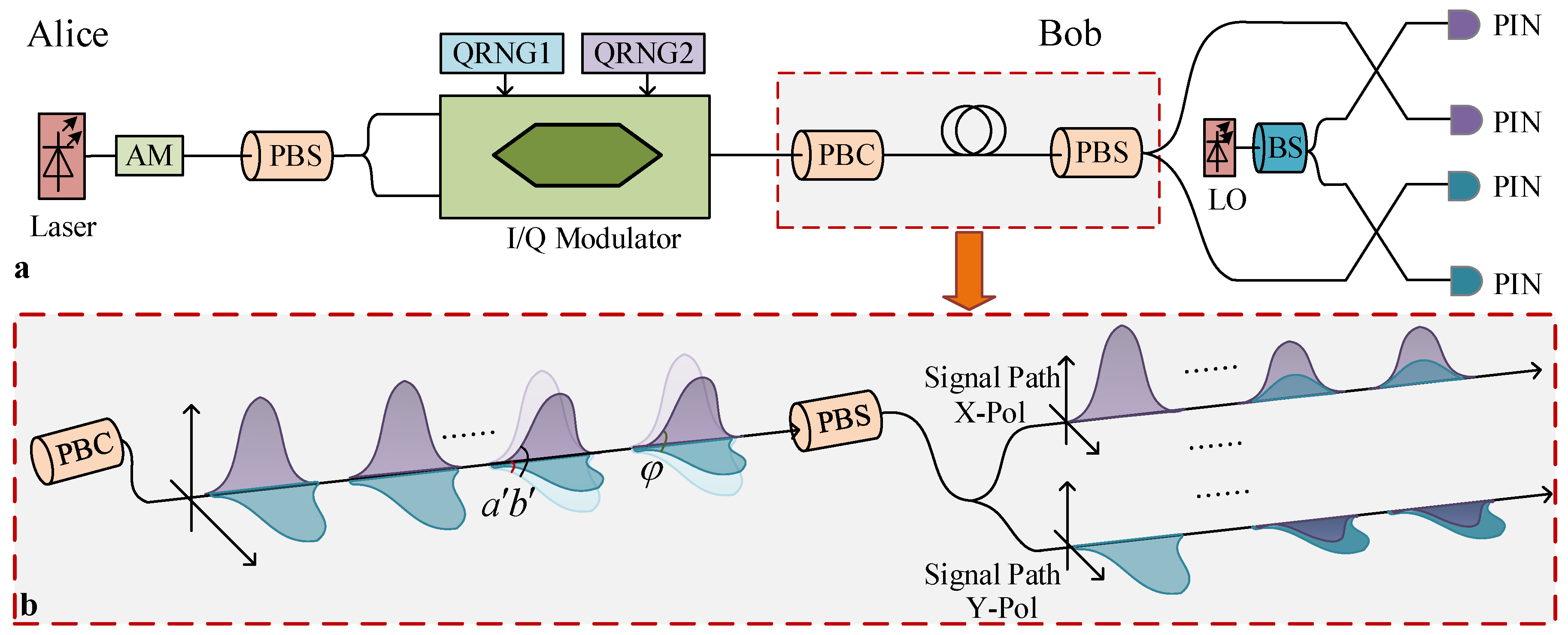
Figure 1. (Color online.) (a) The discretely modulated PDM-based continuous-variable quantum key distribution (CVQKD) system. PBS: polarization beam splitter. PBC: polarization beam combiner. LO: local oscillation. (b) The transmission of two polarizations. The orthogonality of two polarizations is destroyed due to the non-negligible polarization dependent loss (PDL).
Applsci 09 03937 g001
Figure 2. (Color online.) (a) Schematic PDL diagram. After transmission, two polarization states lose their orthogonality, with the different loss in their polarization directions. (b) PDL distributed model. PDLE: PDL emulator. ASE: amplified spontaneous emission.
Applsci 09 03937 g002
Figure 3. (a) The effect of PDL on the components of the electric. (b) Orthogonality of two polarizations with increase of μ .
Applsci 09 03937 g003
Figure 4. (Color online.) Polarization-division-multiplexing (PDM)-quadrature phase shift modulation (QPSK) optical transmitter.
Applsci 09 03937 g004
Figure 5. (Color online.) The polarization-pairwise coding (PPC)-based CVQKD system with PDM-QPSK. (a) Transmitter polarization-pairwise pre-coding. (b) Receiver polarization-pairwise decoding.
Applsci 09 03937 g005
Figure 6. Signal-to-noise ratio (SNR) difference between two polarizations due to PDL.
Applsci 09 03937 g006
Figure 7. The resulting error rate with SNR for S N R = 3 d B .
Applsci 09 03937 g007
Figure 8. The I ( a : b ) with SNR for S N R = 3 d B .
Applsci 09 03937 g008
Figure 9. Parameter relationships in the PDM-based system. (a) The secret key rate as a function of modulation variance V M in different excess noise with transmission distance d = 100 km. (b) The secret key rate as a function of excess noise in different modulation variance V M with transmission distance d = 100 km.
Applsci 09 03937 g009
Figure 10. The secret key rate as a function of transmission distance.
Applsci 09 03937 g010
Table 1. The main parameters of the CVQKD protocol in the security analysis.
SymbolMeaning
T 0 k the equivalent transmittance of quantum channel after PPC scheme
ε 0 k the equivalent excess noise of quantum channel after PPC scheme
ε p d l the excess noise due to lack of orthogonality
e a b the error rate between Alice and Bob after coherent detection