Abstract
The measurement of in-plane displacement in two orthogonal directions is of considerable significance for modern industries. This paper reports on a spatial carrier phase-shift digital speckle pattern interferometry (DSPI) for the simultaneous measurement of in-plane displacement in two orthogonal directions. The object is illuminated from a single direction and observed from four symmetrical directions simultaneously. One pair of the four observation directions is sensitive to in-plane displacement in one direction, and the other pair is sensitive to in-plane displacement in the perpendicular direction, resulting in the displacement in two directions being measured independently. The polarization property of light is used to avoid cross-interference between the two pairs of beams. Spatial carrier frequencies are generated by aperture misalignment, and the displacement in two directions is modulated onto the same interferogram. With a spatial carrier phase-shift technique, the displacement can be separated in the frequency domain and the phase can be evaluated from a single interferogram in real time. The capability of DSPI is described by theoretical discussions and experiments.
1. Introduction
Owing to the rapid development in the manufacturing industry, such as automobile and aerospace applications, measuring the surface displacement of complex mechanical structures and new materials is important. The surface displacement can be further translated into strain and stress, which is the key parameter for design, manufacturing, and quality control [1]. A dynamic full-field and highly sensitive measurement of displacement is the foundation of rapid and optimization design.
The measurement of a three dimensional displacement, along three mutually orthogonal directions, can be classified as out-of-plane and in-plane displacements. However, the in-plane displacement component is more important than the out-of-plane displacement component in many practical problems [2]. Information on in-plane displacement is helpful in determining Young’s modulus and Poisson’s ratio of materials [3,4]. In-plane rotations, which can be determined by in-plane displacement, is an essential component of the geometrical metrology [5,6,7]. Under similar testing conditions, residual stress, obtained from in-plane displacements, has higher precision than that obtained from out-of-plane displacement [8].
Optical measurement techniques have been widely used in displacement measurements because they are non-contact, full-field, and highly sensitive. Advanced optical methods include, digital image correlation (DIC) [9,10], Moiré interferometry [11], and digital speckle pattern interferometry (DSPI) [3,12]. The sensitivity of Moiré interferometry and DSPI is higher than that of DIC, and the set-up of DSPI is simpler than that of Moiré interferometry. Because of the high sensitivity and flexibility of DSPI, it has been well-accepted in experimental mechanics, displacement and displacement measurements, and strain measurements.
In DSPI, in-plane displacement is measured by evaluating the phase difference of two recorded speckle interferograms under load. The surface under the test is illuminated from two symmetrical directions with a single direction of observation [13], or is observed from two symmetrical directions with a single direction of illumination [14]. The measurement of a surface displacement in two orthogonal directions is often required for the complete characterization of displacement. In traditional DSPI, in-plane displacement is measured in the single direction, depending on the illumination or observation direction. For example, if the surface is illuminated from two symmetrical directions, the measured displacement is in the vector direction, which is the subtraction of the vector directions of the two illumination beams. To measure the displacement in the perpendicular direction, the illumination beams must be rotated 90 degrees around the viewing axis. To make a system sensitive to displacement in two orthogonal directions, two pairs of beams, with different directions, should sequentially illuminate the surface. Thus, two separate interferograms can be recorded and combined vectorially [1,3,8,15]. To avoid cross-interference between the two pairs of beams, they should not illuminate the surface at the same time. Sequential measurement takes more time than usual, making the simultaneous measurement of transient or non-repeatable events, that require displacement in two orthogonal directions, unsuitable. Therefore, an interferometer, capable of measuring two in-plane displacements at the same time, is needed.
By using two cameras and two orthogonal polarized dual-beam illumination sets, cross-interference between the two pairs of beams can be avoided, allowing the measurement of the two interferograms at the same time [2]. However, the effectiveness of this method depends on the surface not changing the polarization of the incident beams, which is not always the case [16].
The spatial coherence of the laser can also be used to avoid cross-interference [12]. If the optical lengths are equal for each pair of beams, and the optical length difference between two pairs is longer than the coherent length, the two pairs of beams can illuminate the surface at the same time without cross-interference [17]. However, the temporal phase-shift method is used in this research, making the real-time measurement impossible to conduct. The temporal phase-shift technique solves the phase distribution from multi-interferograms in a time series [1,18]. Given that the phase may vary dramatically while acquiring multi-interferograms, the temporal phase-shift technique is mainly suitable for displacement measurement with a static or quasi-static loading.
By employing the Fourier transformation method, the phase distribution can be calculated from a single interferogram [19,20]. By using three illuminating sources, three interference fringe patterns can be recorded in a single interferogram, and are spatially separated in the Fourier domain, allowing the simultaneous measurement of two in-plane displacement components from one image [21]. However, in this study, the spatial carrier is not introduced, making the measurement of complex displacement unsuitable. By following particular procedures to generate the spatial-carrier frequency, the phase map can be obtained from a single interferogram on the basis of the Fourier transformation procedure, which is named the spatial carrier phase-shift method [22,23,24].
Many researchers have recently proposed digital speckle pattern interferometry, which can measure three-dimensional (3D) displacements by using spatial carrier phase-shift method. Multi-directions of illumination [24,25] or observation [26,27] are used to generate three different sensitivity vectors. Then, the three orthogonal displacement components can be evaluated. The two in-plane displacements can be derived from three-dimensional displacement, which is measured in real time simultaneously. The post calculation of three-dimensional displacement enlarges the uncertainty of measurement. The two in-plane displacements are not independently measured, leading to the coupling of measurement errors, yielded from speckle noise and optical misalignment.
This paper reports a DSPI for the simultaneous and independent measurement of in-plane displacement in two orthogonal directions. Spatial carrier phase-shift technique is used to perform dynamic measurement: only one camera is used, image registration is not needed, and polarization property of light is used to solve the problem of cross interference. Theory derivation, spectrum analysis, and experiment results are shown in detail.
2. Materials and Methods
The optical configuration of the proposed DSPI system is illustrated in Figure 1. A coherent laser, with a wavelength of , is expanded to illuminate the object surface. The object is observed from four directions simultaneously and symmetrically around the z-axis. The four imaging beams are denoted as x1, x2, y1, and y2, and the corresponding wave vectors are , , , and . and are located in the XZ plane, whereas and are located in the YZ plane. The angle between each of observation directions and the z-axis is .
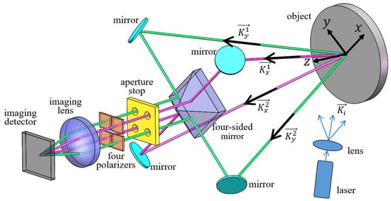
Figure 1.
Schematic diagram of digital speckle pattern interferometry (DSPI) to simultaneously measure two in-plane displacements.
After being reflected by the single mirror and the four-sided mirror, each image passes through the corresponding aperture stop and polarizer, and is imaged onto the image surface by the same lens. The four aperture stops are spatially offset from each other, and a polarizer is placed in front of each aperture stop. The polarization directions of each beam, passing through four polarizers, are illustrated in Figure 2. After passing through the polarizers, the polarizing directions of imaging beams x1 and x2 are the same, and the polarization directions of the imaging beams y1 and y2 are perpendicular to those of beams x1 and x2. Therefore, imaging beam x1 interferes with x2, and imaging beam y1 interferes with y2. No cross interference occurs between the two pairs of beams.
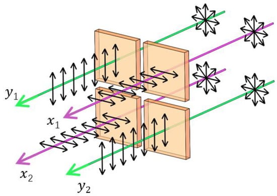
Figure 2.
Polarizing directions of the four imaging beams passing through polarizers.
As shown in Figure 3, are the center coordinates of the four apertures of imaging beams x1, x2, y1, and y2, respectively. The phases of the waves, which pass through the apertures, have a spherical part plus a speckled part [28]. The four beams that pass through each aperture and reach the image plane have amplitudes given by Equation (1) [29,30,31]:
where D is the distance from the image plane to exit pupil plane [32]. and are the spatial carrier frequencies introduced by aperture misalignment.
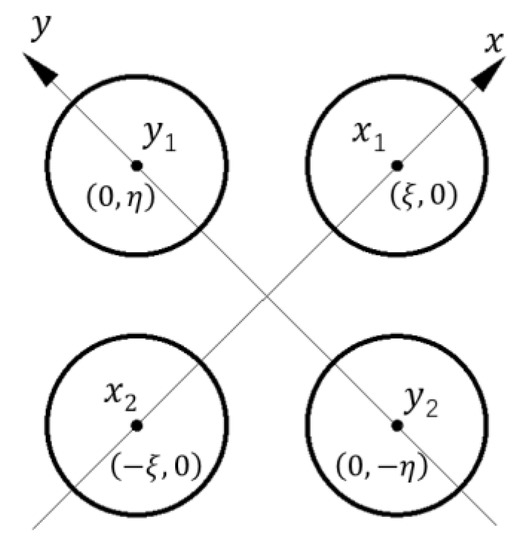
Figure 3.
Schematic diagram of the relative positions of the four apertures in the exit pupil plane.
The interferogram on the imaging plane can be expressed as follows:
By applying Fourier transformation to the interferogram, Equation (2) can be transformed into the Equation (3),
where is the convolution operation, , , and , .
The schematic diagram of the spectrum after Fourier transformation is illustrated in Figure 4. The term contains background information, which is located at the center of the spectrum. The terms and contain the information of in-plane displacement in the x-axis, and they are located at and , respectively. The terms and contain the information of in-plane displacement in the y-axis, and they are located at , and respectively.
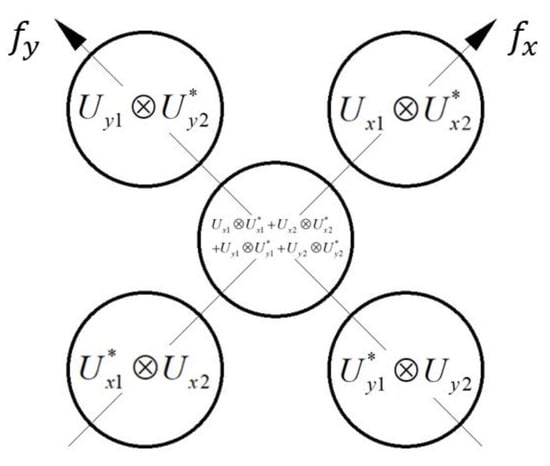
Figure 4.
Schematic diagram of the spectrum distribution of the speckle pattern in the frequency domain.
By properly selecting aperture diameter and distance, the five spectrums on the Fourier domain can be separated. By selecting the term. , located at and performing the inverse Fourier transformation, can be obtained. In the same way, can also be obtained. The phase term can be calculated by the following relation:
where Im and Re denote the imaginary and real parts, respectively. , and are the phase differences of the two pairs of mutually interfering beams.
After displacement, the phase difference can be calculated using Equation (5):
Through subtraction, the displacement can be evaluated from the relative phase difference. The relationship between the phase change and the displacement is given by [21],
where represents the displacement vector of the surface. u and v are the in-plane displacements in the x and y direction, respectively; and w is the out-of-plane displacement. , , and are the unit vectors along the positive x-, y-, and z-axis, respectively. and are the sensitivity vectors, defined as functions of the illumination and observation directions. For the DSPI proposed in this study, the sensitivity vectors can be expressed by Equation (7):
The phase difference that corresponds to the two observation vectors, with a common illumination vector, does not depend on the illumination directions because the observation vector is removed.
From Equations (6) and (7), in-plane displacement in two directions can be calculated by Equation (8):
3. Results
The experiments in this study have been designed to verify the DSPI. A 532 nm laser (Changchun New Industries Optoelectronics Technology Co., Ltd., continuous wave, 200 mW) is used as the laser source. A high-resolution camera (Basler ace, acA1600-20um, 4.4 µm × 4.4 µm pixel size, 1626 pixels × 1236 pixels) is used to record the speckle pattern images. The focal length of the imaging lens is 150 mm. The angle between each wave vector of observation direction and the z-axis is 4°. The diameter of each aperture stop is 4 mm, and the distance of two aperture stops, through which light interferes, is 8 mm. This setting of aperture diameter and distance makes the different terms, shown in Figure 4, separates from each other. If the aperture is too large, or if the distance is too close, the different terms will alias. If the aperture is too small, the amount of light passing through will also be small, and the speckle noise will be large. By choosing an aperture size and distance appropriately, the different terms are evenly distributed to achieve better results.
The object under test is a metal plate with a diameter of 130 mm, which can be precisely rotated in-plane by a micro-head, as illustrated in Figure 5. In-plane displacement is produced by the rigid-body rotation.
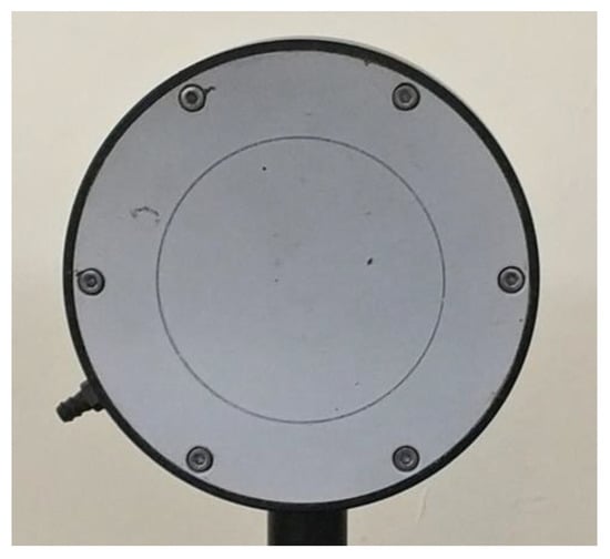
Figure 5.
Object capable of rotating in-plane by a micro-head.
A magnified portion of the recorded speckle pattern image is displayed in Figure 6, which reveals the two orthogonal spatial carrier fringes within the speckle.
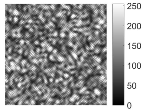
Figure 6.
Enlarged view of the speckle pattern obtained using DSPI.
Figure 7 shows the spectrum distribution of the speckle pattern image after Fourier transformation, which is similar to that obtained theoretically as illustrated in Figure 4. The spectrum shown in Figure 7 is the logarithm of the original spectral intensity to make the figure clearer. The different terms, schematically presented in Figure 4, can be clearly separated in Figure 7. The two terms marked by a red circle and labeled with A and B are corresponding to , and , respectively. According to Equation (3) and Figure 4, the lower terms should be the conjugate of the upper ones. The negative displacement would be determined form the lower terms.
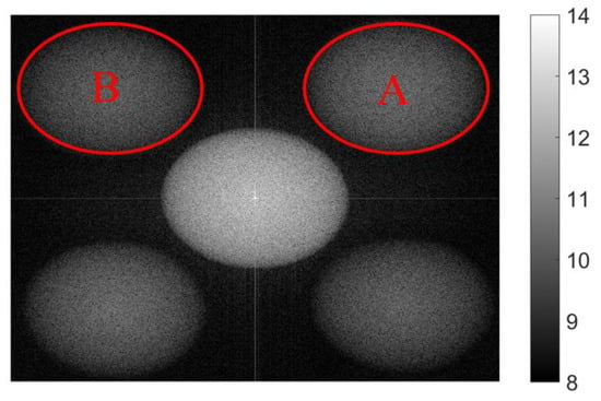
Figure 7.
Spectrum of the recorded interferogram obtained by Fourier transformation.
For both interferograms before and after rotation, by selecting the terms A and B, shown in Figure 7, and applying a windowed inverse Fourier transformation to each term, phase differences and , according to Equation (6), can be extracted. Only two interferograms are needed to evaluate the phase by using spatial carrier phase-shift technique. The phase map is smoothed by a low-pass filter algorithm as displayed in Figure 8(a1,a2). After phase unwrapping, the in-plane displacement in two directions, calculated using Equation (8), is displayed in Figure 8(b1,b2).
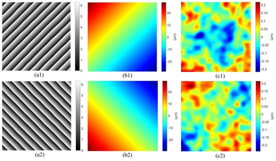
Figure 8.
The smoothed phase and in-plane displacement extracted by the DSPI: (a1) and (a2) are the phase differences , and , respectively; (b1) and (b2) are in-plane displacements in the x-axis direction and y-axis direction respectively; (c1) and (c2) are in-plane displacements errors in the x-axis direction, and y-axis direction, relative to the fitted value, respectively.
Generally speaking, the measurement accuracy and sensitivity of DSPI are mainly determined by the phase map quality and number of times the images are smoothed. Speckle interference is usually able to reach a measuring sensitivity of about 2π/20 to 2π/10 (2π corresponds one fringe) and a measuring accuracy of about 2π/5 to 2π/2. A detailed discussion regarding this topic can be found in reference [33]. In this research, the in-plane displacement is produced by the rigid-body rotation, which follows certain rules demonstrated by Sijin Wu [7]. The displacement reference value is obtained by fitting the measured in-plane displacements according to the rules. Then, the errors of the measured displacements, relative to the reference value are calculated, as shown in Figure 8(c1,c2). The root-mean-square (RMS) errors of in-plane displacements in the x-axis direction and y-axis direction are 0.071 μm, and 0.072 μm respectively, which exhibits high accuracy.
Because the displacement, shown in Figure 8, is produced by an in-plane rotation, the contours of the absolute in-plane displacement are essentially a set of concentric circles around the rotation center. The synthetic in-plane displacement vectors are illustrated in Figure 9, with the contours of the absolute in-plane displacement. The vectors are tangent to the corresponding displacement contours, satisfying the law of displacement introduced by rigid body rotation. The direction of rotation can be easily distinguished from the directions of the in-plane displacement vectors.
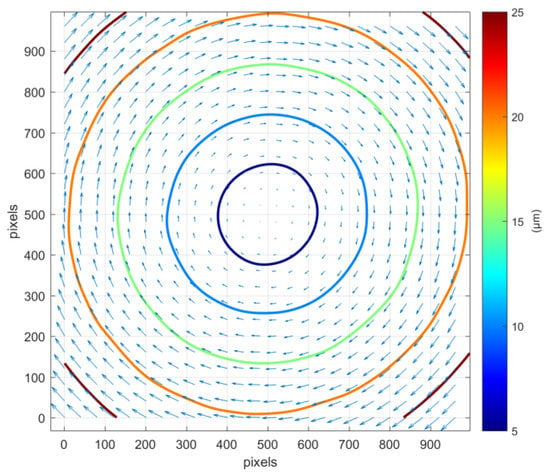
Figure 9.
Synthetic in-plane displacement vectors and contours of the absolute in-plane displacement.
Because only one interferogram is needed to measure the phase in this experiment, the interferogram can be continuously acquired during the displacement of the object. Thereby, the displacement at any acquisition time can be evaluated. Therefore, dynamic measurements can be made, and the measurement speed depends on the frame rate of the camera.
4. Discussion
This work presents a spatial carrier phase-shift DSPI for the simultaneous measurement of in-plane displacement, in two orthogonal directions, by using a single camera. The carrier frequency is generated by aperture misalignment. Two pairs of observation beams are used to make the DSPI sensitive to in-plane displacement in two directions. Considering that the beams, whose polarization directions are perpendicular, do not interfere with each other, cross-interference between the two pairs of beams is avoided. Using the Fourier transformation procedure, the phase can be evaluated from a single interferogram by the spatial carrier phase-shift technique. Only two interferograms are required to simultaneously measure the displacement in two directions: The first image is acquired before the load and the second image is acquired after the load. The displacements in two directions are measured independently, dynamically, and simultaneously, making the DSPI suitable for dynamic and high-accuracy testing.
Author Contributions
Conceptualization, P.Y.; data curation, S.Z.; funding acquisition, Y.W.; investigation, P.Y.; methodology, X.L.; software, F.S.; supervision, Y.W.; validation, X.L.; visualization, F.S. and Q.Z.; writing—original draft, P.Y.; writing—review and editing, P.Y.
Funding
This research was funded by National Natural Science Foundation of China (No. 51805137); Natural Science Foundation of Anhui Province (No. 1808085QE129); the Fundamental Research Funds for the Central Universities of China (JZ2019HGTB0076); the open project of Anhui Province Key Laboratory of Non-Destructive Evaluation, Hefei ZC Optoelectronic Technologies Ltd. (No. CGHBMWSJC04); and the open project of Key Laboratory of Micro Opto-electro Mechanical System Technology, Tianjin University, Ministry of Education (No. MOMST2015-6).
Acknowledgments
The authors would like to express their sincere thanks to Mingzhai Sun from University of Science and Technology of China, who made careful correction of the English for the manuscript.
Conflicts of Interest
The authors declare no conflict of interest.
References
- Yang, L.; Xie, X.; Zhu, L.; Wu, S.; Wang, Y. Review of electronic speckle pattern interferometry (ESPI) for three dimensional displacement measurement. Chin. J. Mech. Eng. 2014, 27, 1–13. [Google Scholar] [CrossRef]
- Moore, A.J.; Tyrer, J.R. Two-dimensional strain measurement with ESPI. Opt. Lasers Eng. 1996, 24, 381–402. [Google Scholar] [CrossRef]
- Francisco, J.B.P.; Michtchenko, A.; Perez, O.B.; Huerta, O.S. Measurement of Young’s modulus and Poisson’s ratio of metals by means of ESPI using a digital camera. Eur. J. Phys. 2016, 37, 11. [Google Scholar] [CrossRef]
- Michtchenko, A. Application of Electronic Speckle Pattern Interferometry Method for Simultaneous Measurement of Young’s Modulus and the Poisson’s Ratio of Metals. Proceedings 2018, 2, 521. [Google Scholar] [CrossRef]
- Lu, M.; Wang, S.J.; Aulbach, L.; Jakobi, M.; Koch, A.W. Non-phase unwrapping interferometric approach for a real-time in-plane rotation measurement. Opt. Lett. 2017, 42, 1986–1989. [Google Scholar] [CrossRef]
- Wang, S.; Lu, M.; Bilgeri, L.M.; Jakobi, M.; Bloise, F.S.; Koch, A.W. Temporal electronic speckle pattern interferometry for real-time in-plane rotation analysis. Opt. Express 2018, 26, 8744–8755. [Google Scholar] [CrossRef] [PubMed]
- Wu, S.; Yang, J.; Li, W.; Wu, F.; Dong, M. Precision roll angle measurement based on digital speckle pattern interferometry. Meas. Sci. Technol. 2019, 30, 045005. [Google Scholar] [CrossRef]
- Asundi, A.K.; Zhang, J. Industrial applications of residual stress determination using 2D in-plane sensitive fiber ESPI and hole drilling. In Proceedings of the Optical Engineering for Sensing and Nanotechnology (ICOSN ′99), Yokohama, Japan, 16–18 June 1999; p. 4. [Google Scholar]
- Shadmehri, F.; Hoa, S.V. Digital Image Correlation Applications in Composite Automated Manufacturing, Inspection, and Testing. Appl. Sci. 2019, 9, 18. [Google Scholar] [CrossRef]
- Blenkinsopp, R.; Roberts, J.; Harland, A.; Sherratt, P.; Smith, P.; Lucas, T. A Method for Calibrating a Digital Image Correlation System for Full-Field Strain Measurements during Large Deformations. Appl. Sci. 2019, 9, 2828. [Google Scholar] [CrossRef]
- Mohammadi, F.; Kofman, J. Multi-Wavelength Digital-Phase-Shifting Moiré Based on Moiré Wavelength. Appl. Sci. 2019, 9, 1917. [Google Scholar] [CrossRef]
- Gao, X.; Yang, L.; Wang, Y.; Zhang, B.; Dan, X.; Li, J.; Wu, S. Spatial phase-shift dual-beam speckle interferometry. Appl. Opt. 2018, 57, 414–419. [Google Scholar] [CrossRef]
- Leendertz, J.A. Interferometric displacement measurement on scattering surfaces utilizing speckle effect. J. Phys. E Sci. Instrum. 1970, 3, 214–218. [Google Scholar] [CrossRef]
- Duffy, D.E. Moiré Gauging of In-Plane Displacement Using Double Aperture Imaging. Appl. Opt. 1972, 11, 1778–1781. [Google Scholar] [CrossRef] [PubMed]
- Bowe, B.; Martin, S.; Toal, V.; Langhoff, A.; Whelan, M. Dual in-plane electronic speckle pattern interferometry system with electro-optical switching and phase shifting. Appl. Opt. 1999, 38, 666–673. [Google Scholar] [CrossRef]
- Viotti, M.R.; Albertazzi, A.; Kaufmann, G.H. Measurement of residual stresses using local heating and a radial in-plane speckle interferometer. OPTICE 2005, 44, 9. [Google Scholar] [CrossRef]
- Fan, H.; Wang, J.; Tan, Y. Simultaneous measurement of whole in-plane displacement using phase-shifting ESPI. Opt. Lasers Eng. 1997, 28, 249–257. [Google Scholar] [CrossRef]
- Qin, J.; Gao, Z.; Wang, X.; Yang, S. Three-Dimensional Continuous Displacement Measurement with Temporal Speckle Pattern Interferometry. Sensors 2016, 16, 2020. [Google Scholar] [CrossRef]
- Takeda, M.; Ina, H.; Kobayashi, S. Fourier-transform method of fringe-pattern analysis for computer-based topography and interferometry. J. Opt. Soc. Am. 1982, 72, 156–160. [Google Scholar] [CrossRef]
- Zhao, Q.; Dan, X.; Sun, F.; Wang, Y.; Wu, S.; Yang, L. Digital Shearography for NDT: Phase Measurement Technique and Recent Developments. Appl. Sci. 2018, 8, 2662. [Google Scholar] [CrossRef]
- Martínez, A.; Rayas, J.A.; Meneses-Fabián, C.; Anguiano-Morales, M. Simultaneous measurement with one-capture of the two in-plane components of displacement by electronic speckle pattern interferometry. Opt. Commun. 2008, 281, 4291–4296. [Google Scholar] [CrossRef]
- Pedrini, G.; Zou, Y.; Tiziani, H. Quantitative evaluation of digital shearing interferogram using the spatial carrier method. Pure Appl. Opt. J. Eur. Opt. Soc. Part A 1996, 5, 313. [Google Scholar] [CrossRef]
- Xin, X.; Xiaona, L.; Xu, C.; Lianxiang, Y. Review of recent developments of spatial phase-shift digital shearography. Proc. Spie 2015, 9302, 93020E. [Google Scholar] [CrossRef]
- Gao, X.Y.; Wang, Y.H.; Li, J.R.; Dan, X.Z.; Wu, S.J.; Yang, L.X. Spatial carrier color digital speckle pattern interferometry for absolute three-dimensional deformation measurement. OPTICE 2017, 56, 066107. [Google Scholar] [CrossRef]
- Fang, Y.; Wu, S.; Yang, L. Synchronous Measurement of Three-Dimensional Deformations Using Tri-Channel Spatial-Carrier Digital Speckle Pattern Interferometry. Appl. Mech. Mater. 2017, 868, 316–322. [Google Scholar] [CrossRef]
- Lu, M.; Wang, S.; Bilgeri, L.; Song, X.; Jakobi, M.; Koch, A.W. Online 3D Displacement Measurement Using Speckle Interferometer with a Single Illumination-Detection Path. Sensors 2018, 18, 1923. [Google Scholar] [CrossRef] [PubMed]
- Wang, Y.; Sun, J.; Li, J.; Gao, X.; Wu, S.; Yang, L. Synchronous measurement of three-dimensional deformations by multicamera digital speckle patterns interferometry. OPTICE 2016, 55, 091408. [Google Scholar] [CrossRef]
- Sirohi, R.S.; Burke, J.; Helmers, H.; Hinsch, K.D. Spatial phase shifting for pure in-plane displacement and displacement-derivative measurements in electronic speckle pattern interferometry (ESPI). Appl. Opt. 1997, 36, 5787–5791. [Google Scholar] [CrossRef][Green Version]
- Bhaduri, B.; Mohan, N.K.; Kothiyal, M.P. Simultaneous measurement of out-of-plane displacement and slope using a multiaperture DSPI system and fast Fourier transform. Appl. Opt. 2007, 46, 5680–5686. [Google Scholar] [CrossRef]
- Lu, M.; Wang, S.; Aulbach, L.; Koch, A.W. Simultaneous displacement and slope measurement in electronic speckle pattern interferometry using adjustable aperture multiplexing. Appl. Opt. 2016, 55, 5868–5875. [Google Scholar] [CrossRef]
- Barrera, E.S.; Fantin, A.V.; Willemann, D.P.; Benedet, M.E.; Goncalves, A.A. Multiple-aperture one-shot shearography for simultaneous measurements in three shearing directions. Opt. Lasers Eng. 2018, 111, 86–92. [Google Scholar] [CrossRef]
- Yan, P.; Sun, F.; Dan, X.; Zhao, Q.; Wang, Y.; Lu, Y. Spatial phase-shift digital shearography for simultaneous measurements in three shearing directions based on adjustable aperture multiplexing. OPTICE 2019, 58, 054105. [Google Scholar] [CrossRef]
- Steinchen, W.; Yang, L.X.; Kupfer, G.J.E.T. Digital shearography for nondestructive testing and vibration analysis. Exp. Tech. 1997, 21, 20–23. [Google Scholar] [CrossRef]
© 2019 by the authors. Licensee MDPI, Basel, Switzerland. This article is an open access article distributed under the terms and conditions of the Creative Commons Attribution (CC BY) license (http://creativecommons.org/licenses/by/4.0/).