Article

Non-Linear Vibration Isolators with Unknown Excitation and Unmodelled Dynamics: Sliding Mode Active Control

1
School of Mechanical Engineering, Wuhan Polytechnic University, Wuhan 430023, China
2
Hubei Provincial Engineering Technology Research Center of Fish Processing Equipment, Wuhan 430023, China
3
School of Engineering, University of Liverpool, The Quadrangle, Liverpool L693GH, UK
*
Author to whom correspondence should be addressed.
Appl. Sci. 2019, 9(17), 3567; https://doi.org/10.3390/app9173567
Submission received: 9 August 2019 / Accepted: 29 August 2019 / Published: 31 August 2019
(This article belongs to the Section Acoustics and Vibrations)

Abstract

:
For a class of single-degree-of-freedom non-linear passive vibration isolators with unknown excitation and unmodelled dynamics, two sliding mode control methods—a conventional one and the other using a super-twisting algorithm—were proposed to complement and improve the performances and the robustness of the passive isolators. The proposed control methods only require the estimation of the loading and measured velocities of the isolators. Numerical simulations for a non-linear isolator with quasi-zero stiffness demonstrated that both methods were effective and easy to implement, and the one using a super-twisting algorithm was more promising from the perspective of practical application.

1. Introduction

Non-linear passive vibration isolators have been proven to be advantageous to overcome the inherent drawback of linear isolators in different applications [1]. Thus, the effects of non-linear stiffness or/and damping on an isolator’s performance have drawn a lot of attention; see, for example, [2,3,4,5,6]. It is known that a non-linear isolator performs well over larger frequency ranges compared to a corresponding linear isolator. The soft non-linearity of its stiffness reduces the vibration transmissibility in the resonant frequency [7] and the influence of non-linearity on the characteristics of an isolator may also include shifts in resonance frequency, internal resonance, and chaotic response [1,7,8,9,10,11].
Recently, a type of non-linear passive vibration isolator with quasi-zero stiffness (QZS) at the equilibrium position has received increasing attention [10,11,12,13,14,15,16,17,18]. This isolator possesses high-static–low-dynamic stiffness so that it can maintain the load-bearing capacity with a small static displacement and achieve a lower natural frequency to enlarge frequency ranges of vibration isolation. But, it should be noted that isolators with QZS are very sensitive facilities and if something occurs to cause deviation of its characteristic parameters (e.g., mismatch of the load and negative stiffness parameters) and/or change in the non-linearity properties of its forces (e.g., destruction of the symmetry), then the isolation performance will change dramatically [19,20,21,22]. This situation is particularly true when the amplitude of excitation is not relatively small, and the isolator is exposed to a sustained excitation. Therefore, they need careful tuning and fine precision during manufacturing.
Besides, a non-linear passive isolator cannot perform well over all the frequencies that a system may be confronted with, because it is designed and fabricated with predetermined system parameters. A better scheme to overcome these shortcomings is to introduce semi-active or active devices which cooperate with the passive isolators. Such an isolator is referred to as a hybrid isolator. Due to the limitations of the scope of the discussion in this article, we only focused our attention on an active type of hybrid isolator with QZS.
A simple linear time-delayed displacement feedback control strategy was introduced to improve the robustness and transmissibility performance of an isolator with QZS under both force and base excitation in Reference [23]. This control strategy can be used to gain better isolation performance in a resonant region. It was also shown that undesirable bifurcation and chaotic behaviors can be avoided or greatly suppressed when the controlled stiffness and especially the introduced time delay are appropriately chosen. But the performance gets worse in the high-frequency band. In Reference [24], the cubic displacement feedback with time delay was proposed, which can effectively suppress the transmissibility in resonant region and reduce the resonant frequency with the performance in higher frequency range unaffected with appropriate feedback parameters. In Reference [25], the time-delayed cubic velocity feedback control strategy was investigated. It turned out that a better isolation performance in the high-frequency band where isolation is required can also be achieved, but the 1/3 subharmonic resonance can occur for a smaller excitation amplitude and increasing the feedback gain cannot eliminate the 1/3 subharmonic resonance. In these studies, a single-degree-of-freedom (SDOF) oscillator with cubic non-linearity was analyzed by using some approximate analytical methods, e.g., the multiple scales method and the harmonic balance method, and the amplitude–frequency responses were obtained.
These control analyses of hybrid isolators with QZS were conducted based upon good knowledge of mathematical representations of the systems. However, in many practical situations, their mathematical models undoubtedly involve errors in relation to practical systems and quite often are not exactly available. Therefore, advanced control techniques have been required to deal with these situations, such as robust control (including sliding mode control (SMC)), adaptive control, fuzzy logic control, neural-network control, learning control, etc.
This paper proposes two SMC-based active force controllers to complement a class of SDOF non-linear vibration isolators. The targeted isolators can usually be characterized as a class of non-linear systems that contain unknown, bounded uncertainties/disturbances, and unmodelled dynamics. These characteristics are the main reasons for choosing SMC to cope with this class of isolator [26,27,28,29,30,31]. The SMC methods also have other advantages: computational simplicity and easy implementation with respect to other robust control approaches. The main disadvantage of the conventional SMC is the chattering phenomena of the system output and control input, which can induce damages to control systems. Nowadays, the super-twisting SMC algorithm has become preferable over the conventional SMC, since it greatly alleviates the chattering phenomena [30,32,33].
The rest of this paper is organized as follows. The description of the non-linear vibration isolators and the proposed SMC methods are presented in Section 2. Section 3 gives a specific non-linear isolator with QZS and numerical simulations and result analyses of the proposed SMC methods for this isolator are provided. Finally, the concluding remarks are drawn in Section 4.

2. Force Controller Design

Consider an SDOF non-linear vibration isolator with the governing equation of motion represented by:
m x ¨ + ψ 1 ( x , x ˙ , f e ) = f c
where m is the isolated mass, x ¨ , x ˙ , and x are the acceleration, velocity, and displacement of the mass, respectively. ψ 1 ( · ) represents the total effect of the linear/non-linear stiffness restoring forces, damping forces, and the external disturbing forces f e that exert on the mass. f c is an active control force that is used to further suppress vibrations of the mass. In this article, it is assumed in Equation (1) that ψ 1 ( · ) is difficult to be modeled exactly or not easily identifiable and, thus, is deemed to be unknown. Situations where ψ 1 ( · ) cannot be exactly determined occurs in many practical applications, such as when models are not well developed and where there exist seldom-known system parameters or unpredictable parameter variations, etc. Additionally, the mass m in Equation (1) is considered to be uncertain or has its value in a certain interval. Let m ^ be an estimated or nominal value of the mass m , Equation (1) is rearranged as follows:
m ^ x ¨ + ( m m ^ ) x ¨ + ψ 1 ( x , x ˙ , f e ) = f c
Let ψ ( x , x ˙ ,   x ¨ ,   f e ) = ( m m ^ ) x ¨ ψ 1 ( x , x ˙ ,   f e ) , which includes all the system non-linearities and uncertainties and is supposed to be bounded. Then Equation (1) has:
m ^ x ¨ = ψ ( x , x ,   ˙ x ¨ ,   f e ) + f c
In this study, only measurements of the velocity x ˙ were required.
In order to make the non-linear vibration isolator more robust and improve its dynamics behavior, we proposed two SMCs to supplement the isolation performance. In what follows, the SMC methods were implemented, respectively, in this paper: a conventional SMC [29,31] and a SMC based on a super-twisting algorithm [30,32,33]. For the vibration suppression problems discussed here, the desired displacement, velocity, and acceleration trajectory of the isolated mass can be predefined as zeros. Subsequently, a sliding surface (s) for the conventional SMC design was adopted as:
s ( t ) = x ˙ ( t ) + λ x ( t )
where λ > 0 . Therefore, its first-time derivative is given, together with Equation (3), by:
s ˙ ( t ) = x ¨ ( t ) + λ x ˙ ( t ) = λ x ˙ ( t ) + m ^ 1 ψ + m ^ 1 f c ( t )
First, a conventional SMC is introduced to be directly as [34]:
f c ( t ) = m ^ ( λ x ˙ ( t ) + μ s ) D t a n h ( s ε )
where the constant design parameters are ε > 0 ,   μ > 0 , and D | ψ | . In Equation (6), the continuous tanh function is used to replace the discontinuous signum function in order to alleviate the chattering phenomenon of the SMC [29]. The value ε of t a n h ( · ) determines how the tanh can approximate the signum function. A smaller ε , a closer approximation to the signum function was obtained, as shown in Figure 1. The estimation of D can be determined by the estimation of | m ^ x ¨ | from Equation (3). If a large μ is selected, the isolation performances will get better, but the closed-loop stability will be lost when the value of μ is large enough. Additionally, for the stability analysis of the closed-loop control system, it has been proven with a Lyapunov function V = 1 2 s 2 that [31]:
lim t V ( t ) 0.2785 D ε 2 μ m ^
So, the trajectory of the system (3) is asymptotically convergent to a vicinity of zero under the control input (6), and the convergent precision is determined by D , μ , and ε .
Second, for the super-twisting control, a proportional-integral-derivative (PID)-type sliding surface is adopted as:
s ( t ) = x ˙ ( t ) + λ x ( t ) + b 0 t x ( τ ) d τ
where the feedback gains are λ > 0 and b > 0 . Its first-time derivative of sliding surface (s) (8) is given by:
s ˙ ( t ) = x ¨ ( t ) + λ x ˙ ( t ) + b x ( t )
The proposed control input ordinarily consists of two parts [27,32], i.e., the equivalent control f e q c ( t ) and the correction control f c o r r c ( t ) . The equivalent control f e q c ( t ) is obtained from Equation (9) with Equation (3) when s ˙ ( t ) = 0 , which is provided not to account for the presence of unknown disturbances and unmodeled dynamics (i.e., ψ = 0 in Equation (3)). So, one has:
f e q c ( t ) = m ^ ( λ x ˙ ( t ) + b x ( t ) )
Then, f c o r r c ( t ) , using a super-twisting control input, is given by:
f c o r r c ( t ) = D s i g n ( s ( t ) ) α | s ( t ) |   s i g n ( s ( t ) ) β s i g n ( s ( τ ) ) d τ
with α , β > 0 and D | ψ | . This super-twisting control is a variant of the original one [33] as an additional switching item, D s i g n ( s ( t ) ) is added to match the presence of unknown disturbances and unmodeled dynamics, ψ . To sum up, the active control force f c is given by:
f c ( t ) = m ^ ( λ x ˙ ( t ) + b x ( t ) ) ( D + α | s ( t ) | )   s i g n ( s ( t ) ) β s i g n ( s ( τ ) ) d τ
In the sequel, the stability analysis of the proposed controller is investigated with a candidate Lyapunov function V ( t ) = 1 2 s 2 ( t ) . One has from Equations (9) and (3):
V ˙ ( t ) = s s ˙ = s ( x ¨ + λ x ˙ + b x ) = s ( m ^ 1 ψ + m ^ 1 f c + λ x ˙ + b x )
Substituting Equation (12) into Equation (13), one has:
V ˙ ( t ) = s ( m ^ 1 ψ D s i g n ( s ) α | s |   s i g n ( s ) β s i g n ( s ( τ ) ) d τ )
= s ( m ^ 1 ψ m ^ 1 ( D s i g n ( s ) α | s |   s i g n ( s ) β s i g n ( s ) d τ ) )
= m ^ 1 ( ψ s D | s | ) α | s | | s |   β s s i g n ( s ) d τ   < 0   ( for   s 0 )
So, the reaching condition is guaranteed. Additionally, in practice, let α = 1.5 U and β = 1.1 U in Equation (12), where U is a positive constant that needs to be progressively tuned [33]. This single-parameter “trial and error” tuning is used to obtain desired performances of the closed-loop system in practical implementation.

3. Active Control of a Quasi-Zero-Stiffness Isolator

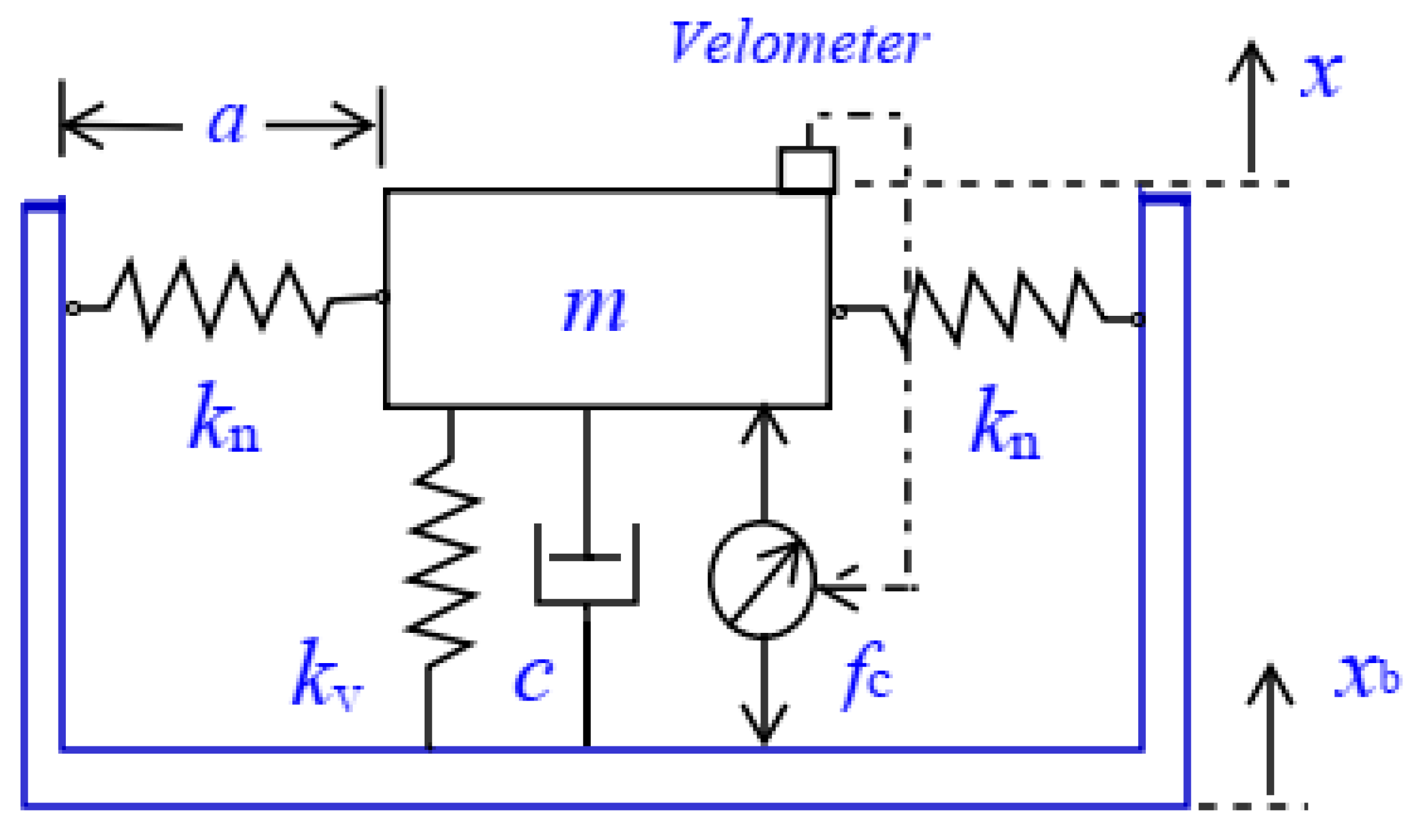
3.1. Description of a Quasi-Zero-Stiffness Isolator

The active force controller described above was applied to a non-linear stiffness vibration isolator with the quasi-zero-stiffness (QZS) mechanism. Such a simple hybrid isolator that combines the passive and active components consisted of some linear springs with one vertical spring connected with several inclined springs, and a linear viscous damper, as shown in Figure 2. This isolator was used to isolate the base excitation x b with the auxiliary control force f c . The isolated body with the mass m was supported above the base by the vertical spring with stiffness k v and its static equilibrium position was set-up while the oblique springs with stiffness k n were compressed in the horizontal position. The damper with linear damping coefficient c was placed in parallel with the vertical spring. The force–deflection relationship of the stiffness elements for the isolator is given by [12,13]:
f = k v ( x x b ) + n k n ( 1 a 0 ( x 2 + a 2 ) 1 / 2 ) ( x x b )
where a is the free length of the oblique springs and a0 is their length when they are in the horizontal position. The equation of motion of the hybrid isolator can be described by:
m x ¨ + c ( x ˙ x ˙ b ) + k v ( x x b ) + n k n ( 1 a 0 ( x 2 + a 2 ) 1 / 2 ) ( x x b ) = f c
where n is the number of oblique springs.
It is the usual case in general that the base excitation x b and x ˙ b are unable to be known accurately beforehand and there are some uncertainties for the physical parameters of the passive isolation components. Now let ψ 1 ( · ) in Equation (1) be:
ψ 1 = c ( x ˙ x ˙ b ) + k v ( x x b ) + n k n ( 1 a 0 ( x 2 + a 2 ) 1 / 2 ) ( x x b )
and ψ ( · ) = ( m m ^ ) x ¨ ψ 1 , then Equation (16) is rewritten as the same formulation as Equation (3), where ψ is also considered to be unknown here. The mass estimation m ^ is supposed to be known beforehand, and its velocity x ˙ is the measured variable required only for the design of the active control force f c . The displacement x can be obtained from the numerical integration of the velocity x ˙ .
For the purpose of numerical simulation, an example of the isolator was utilized to validate the control design proposed in the preceding section. The nominal values of physical parameters of the isolator were m = 300 kg, k v = 15000 N m−1, k n = k v /2.5, c = 85 N s m−1, a = 0.6 m, a0 = 1.0 m, and n = 4. The base excitation x b was a zero-mean Gaussian white noise of standard deviation 0.01 m, which was filtered using a low-pass filter with 15 Hz cut-off frequency. This setup was used to produce state variables of the mass. The simulation was conducted using the ode45 function of MATLAB with a time step of 0.01 s.

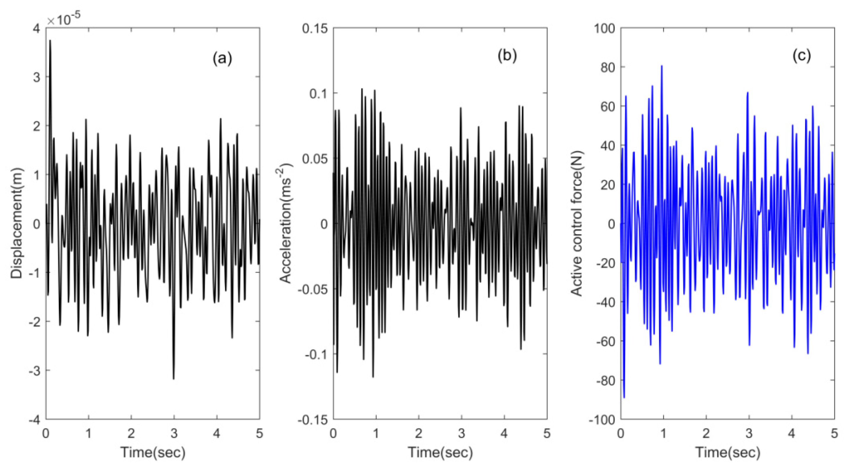
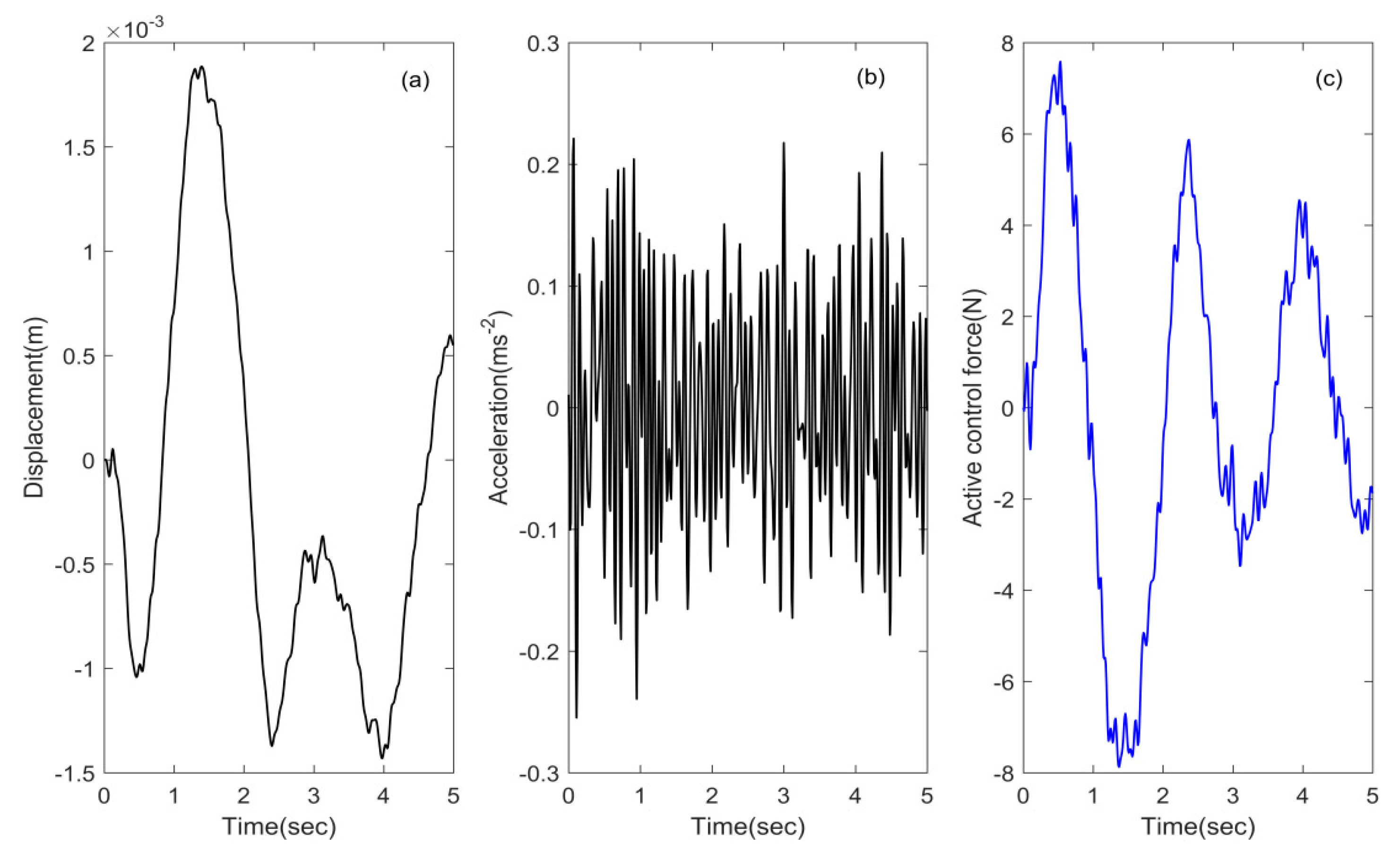
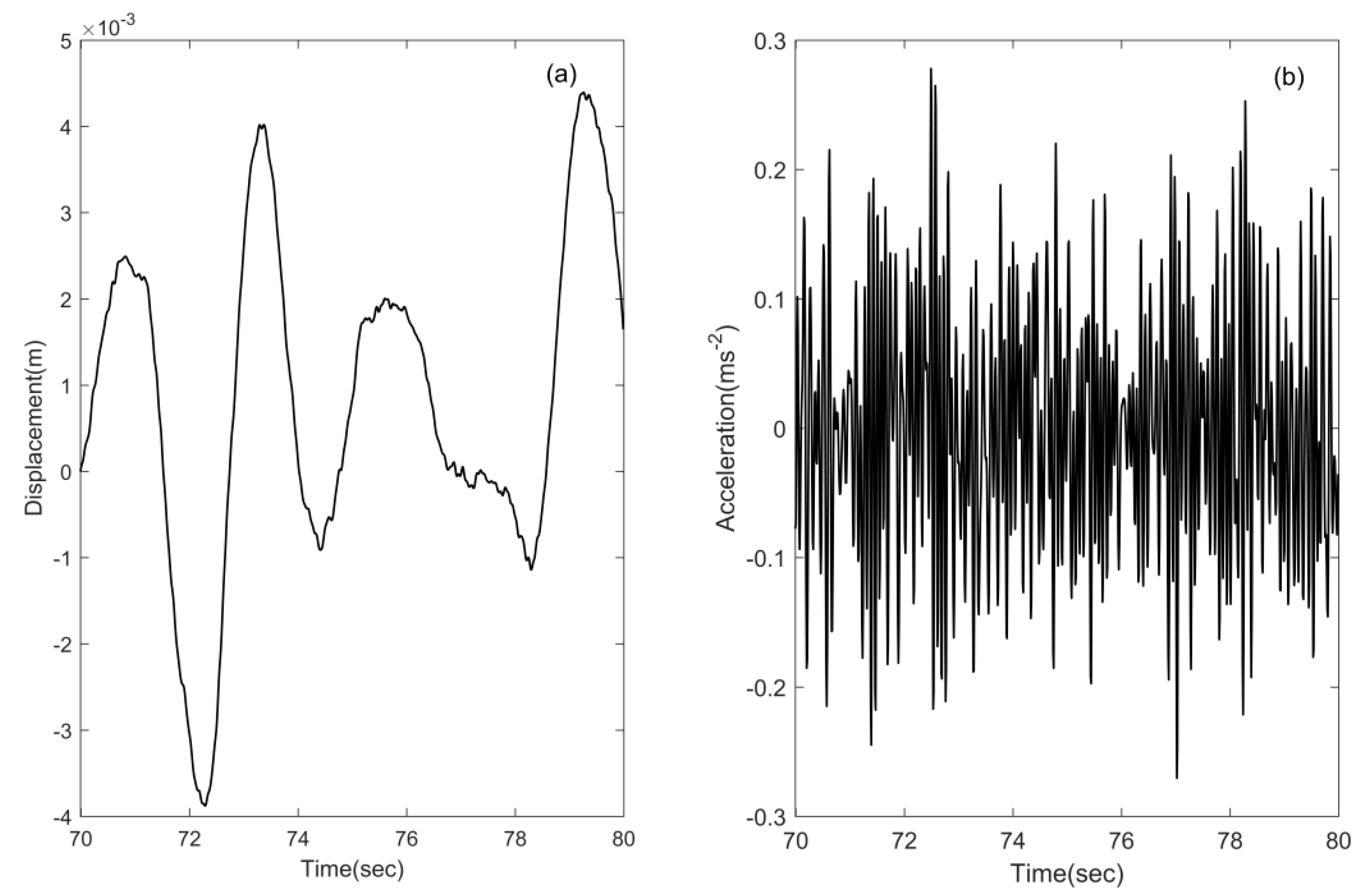
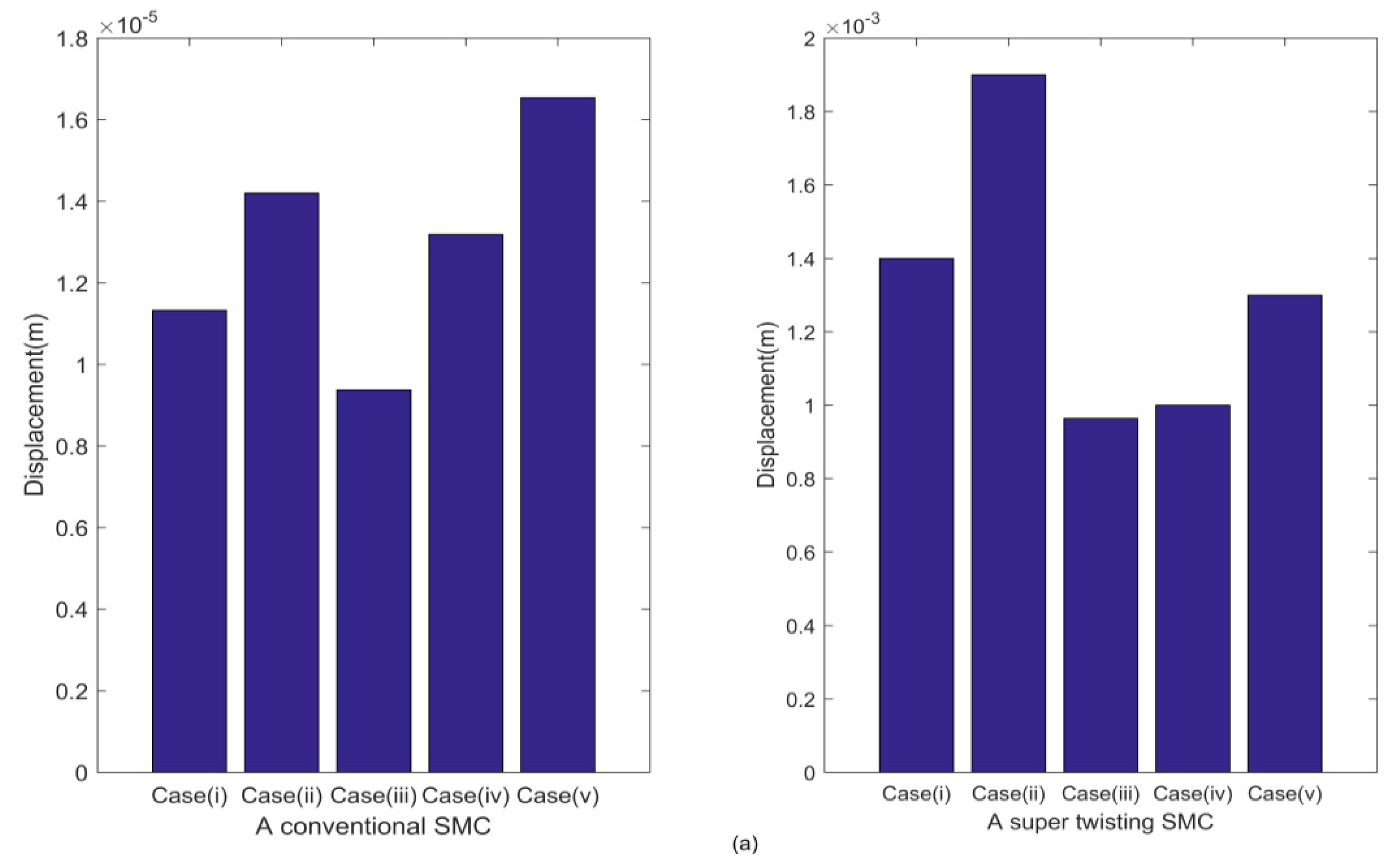
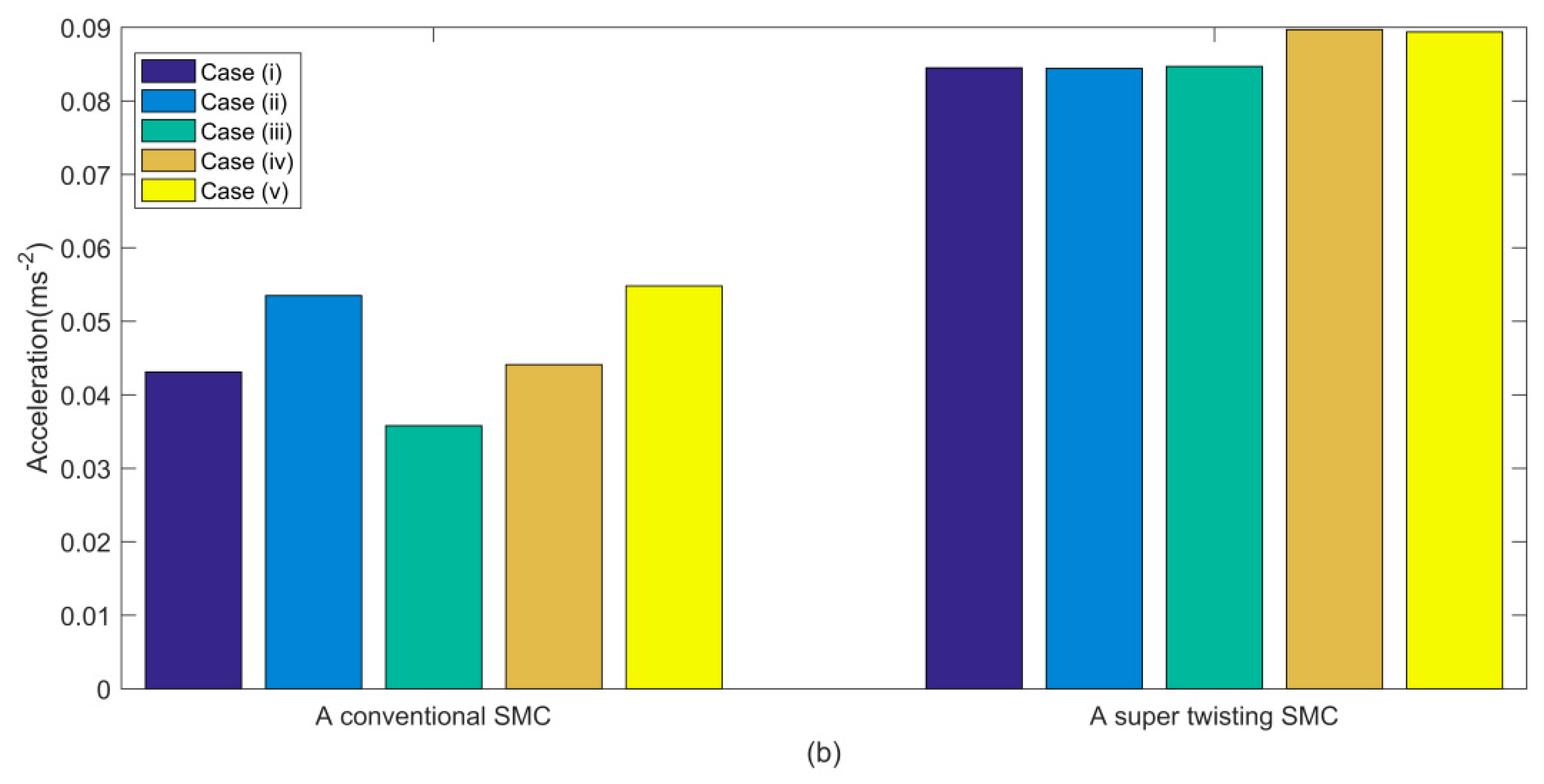
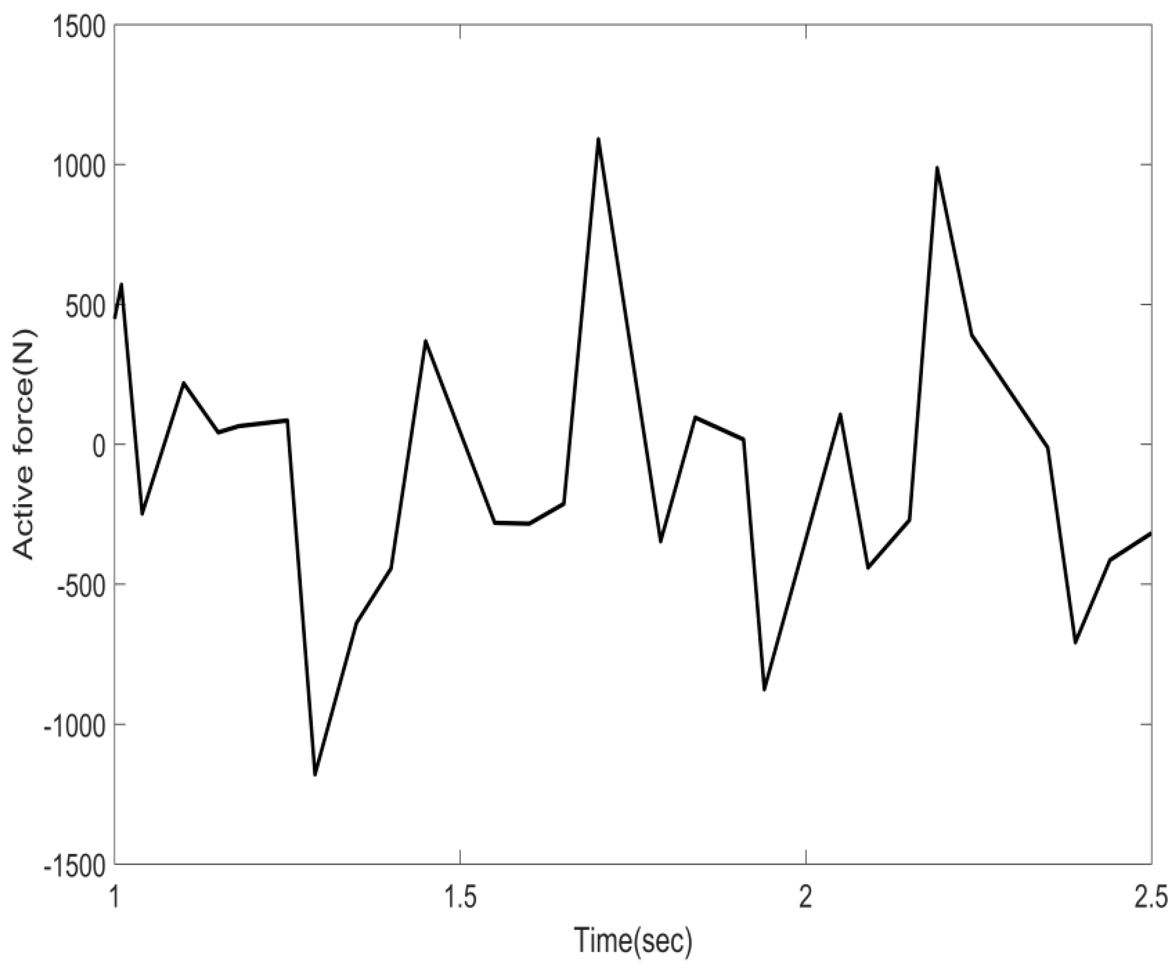
3.2. Simulation Results and Analyses

Two kinds of control forces f c ( t ) from Equations (6) and (12) were used for numerical verification of the control schemes on the isolator. They were applied to five cases involving the set-up of a controller’s parameter m ^ and an isolator’s parameter k n : (i) m ^ = 300 kg and k n was the nominal value ( k n = k v /2.5); (ii) m ^ = 360 kg and k n = k v /2.5; (iii) m ^ = 240 kg and k n = k v /2.5; (iv) m ^ = 300 kg and k n had an approximately 17% decrease, i.e., k n = k v / 3 ; (v) m ^ = 240 kg and k n = k v / 3 . Other parameters of the isolator retained their nominal values. The algorithm parameters of the control forces f c ( t ) were chosen to be μ = 160 , D = 5.0 , λ = 10 , and ε = 0.5 for Equation (6) and U = 4.0 , D = 5.0 , λ = 1.0 , and b = 16 for Equation (12) throughout all cases.
In case (i), Figure 3a–c and Figure 4a–c show responses of displacement and acceleration of the mass under the base excitation of the white noise and the active control forces applied, respectively, for the control algorithms (6) and (12). Figure 5a,b presents responses of displacement and acceleration of the passive isolator with nominal parameter values. Their root mean square (RMS) values of the responses are presented in Table 1 for comparison. Two statements could be presented from the numerical experiments: (I) The conventional SMC provided the best vibration isolation performance at the cost of moderate magnitudes of control forces. But it led to higher frequency oscillations of the responses for displacements on a microscale and the intense chattering for control inputs on a macroscale, which is unacceptable in practical implementation. (II) The super-twisting control gave the second-best results with small magnitudes of control forces. Although only achieving a displacement reduction by 46.15% in the RMS values and 8.65% in the acceleration reduction compared with the corresponding passive isolator with QZS, it produced moderate oscillating responses and fewer chattering occurrences, which is also important and preferable in practical applications, compared with those given by the conventional SMC.
For cases (ii) to (v), numerical experiments were conducted to investigate the robustness of the control schemes for the hybrid isolator. The RMS values of the responses are presented in Figure 6. Although the RMS values of the displacement responses with the super-twisting control showed some variations, as shown in Figure 6a, they were all smaller than that of the corresponding passive isolator with QZS. It was demonstrated that the hybrid isolator with the proposed control methods had robust vibration isolation performances with respect to the estimation error of m ^ and the system parametric variations, and could overcome the essential defect of the non-linear passive isolators with QZS, i.e., their performances were very sensitive to the deviations in system parameters.

3.3. Additional Comments

The hybrid isolator with QZS can have less control forces compared with those without QZS. In Reference [34], a sliding mode controller was developed by considering loading uncertainty to a suspension system. The semi-active control forces were provided by a magnetorheological fluid damper. In its simulation results for an isolator with the same mass and the vertical spring with stiffness k v as those of the isolator described in Section 3.1, the large control forces were presented under random base excitation with standard deviation 0.01 m and within the 0.5–10 Hz frequency range, as shown in Figure 7. Their RMS values for acceleration and displacement were 0.48 ms−2 and 6.70 × 10⁻³ m (see Table 3 in Reference [34]), respectively. Clearly, the control methods proposed in this paper for the hybrid isolator with QZS offers a number of advantages over those given in Reference [34].

4. Conclusions

This paper proposed two SMC methods for the non-linear vibration isolator with QZS. The control schemes weredesigned without the need forany knowledge onanalytic models of the isolator andwas only based on the estimation of the loading and measured velocities of the isolator. The hybrid isolator using the conventional SMC and the super-twisting SMC proposed in this paper can acquire better vibration isolation performances, and has specific advantages, i.e., robustness against parameter variations and unmodelled dynamics. The super-twisting SMC is a promising technique for non-linear hybrid isolators from the perspective of practical application. Future research will be focused on further improvement of isolation performances using, e.g., a second-order sliding mode control based on adaptive and time-varying gains.

Author Contributions

Conceptualization, J.-F.Z. and H.O.; Methodology, J.-F.Z.; Software, Z.-G.H.; Validation, K.-W.Z., Z.-G.H. and H.-M.L.; Data Curation, K.-W.Z. and H.-M.L.; Writing—Original Draft Preparation, K.-W.Z. and J.-F.Z.; Writing—Review & Editing, H.O.; Supervision, J.-F.Z.

Funding

This research received no external funding.

Conflicts of Interest

The authors declare no conflict of interest.

References

  1. Ibrahim, R.A. Recent advances in non-linear passive vibration isolators. J. Sound Vib. 2008, 314, 371–452. [Google Scholar] [CrossRef]
  2. Hundal, M.S. Response of shock isolators with linear and quadratic damping. J. Sound Vib. 1981, 76, 273–281. [Google Scholar] [CrossRef]
  3. Ravindra, B.; Mallik, A.K. Performance of non-linear vibration isolators under harmonic excitation. J. Sound Vib. 1994, 170, 325–337. [Google Scholar] [CrossRef]
  4. Amer, Y.A.; EL-Sayed, A.T. Vibration suppression of non-linear system via non-linear absorber. Commun. Non-linear Sci. Numer. Simul. 2008, 13, 1948–1963. [Google Scholar] [CrossRef]
  5. Peng, Z.; Lang, Z.; Jing, X.; Billings, S.; Tomlinson, G.; Guo, L. The transmissibility of vibration isolators with a non-linear antisymmetric damping characteristic. J. Vib. Acoust. 2010, 132, 014501. [Google Scholar] [CrossRef]
  6. Huang, X.; Sun, J.; Hua, H.; Zhang, Z. The isolation performance of vibration systems with general velocity-displacement-dependent non-linear damping under base excitation numerical and experimental study. Non-linear Dyn. 2016, 85, 777–796. [Google Scholar] [CrossRef]
  7. Kolovsky, M.Z. Non-linear Dynamics of Active and Passive Systems of Vibration Protection; Springer: Berlin, Germany, 1999. [Google Scholar]
  8. Dantas, M.; Balthazar, J. A comment on a nonideal centrifugal vibrator machine behavior with soft and hard springs. Int. J. Bifurc. Chaos 2006, 16, 1083–1088. [Google Scholar] [CrossRef]
  9. Tusset, A.; Balthazar, J. On the chaotic suppression of both ideal and non-ideal duffing based vibrating systems, using a magnetorheological damper. Differ. Eq. Dyn. Syst. 2013, 21, 105–121. [Google Scholar] [CrossRef]
  10. Kovacic, I.; Brennan, M.J.; Waters, T.P. A study of a non-linear vibration isolator with a quasi-zero stiffness characteristic. J. Sound Vib. 2008, 315, 700–711. [Google Scholar] [CrossRef]
  11. Ahn, H.J. Performance limit of a passive vertical isolator. J. Mec. Sci. Technol. 2008, 22, 2357–2364. [Google Scholar] [CrossRef]
  12. Carrella, A.; Brennan, M.J.; Waters, T.P. Static analysis of a passive vibration isolation with quasi zero-stiffness characteristic. J. Sound Vib. 2007, 301, 678–689. [Google Scholar] [CrossRef]
  13. Carrella, A.; Brennan, M.J.; Waters, T.P., Jr.; Lopes, V. Force and displacement transmissibility of a non-linear isolator with high-static-low-dynamicstiffness. Int. J. Mech. Sci. 2012, 55, 22–29. [Google Scholar] [CrossRef]
  14. Zhou, N.; Liu, K. A tunable high-static-low-dynamic stiffness vibration isolator. J. Sound Vib. 2010, 329, 1254–1273. [Google Scholar] [CrossRef]
  15. Robertson, W.S.; Kidner, M.R.F.; Cazzolato, B.S.; Zander, A.C. Theoretical design parameters for a quasi-zero stiffness magnetic spring for vibration isolation. J. Sound Vib. 2009, 326, 88–103. [Google Scholar] [CrossRef]
  16. Xu, D.L.; Yu, Q.P.; Zhou, J.X.; Bishop, S.R. Theoretical and experimental analyses of a non-linear magnetic vibration isolator with quasi-zero-stiffness characteristic. J. Sound Vib. 2013, 332, 3377–3389. [Google Scholar] [CrossRef]
  17. Liu, X.T.; Huang, X.C.; Hua, H.X. On the characteristics of a quasi-zero stiffness isolator using Euler buckled beam as negative stiffness corrector. J. Sound Vib. 2013, 332, 3359–3376. [Google Scholar] [CrossRef]
  18. Yang, J.; Xiong, Y.P.; Xing, J.T. Dynamics and power flow behaviour of a non-linear vibration isolation system with a negative stiffness mechanism. J. Sound Vib. 2013, 332, 167–183. [Google Scholar] [CrossRef]
  19. Huang, X.C.; Liu, X.T.; Sun, J.Y.; Zhang, Z.Y.; Hua, H.X. Effect of the system imperfections on the dynamic response of a high-static-low-dynamic stiffness vibration isolator. Non-linear Dyn. 2014, 76, 1157–1167. [Google Scholar] [CrossRef]
  20. Cheng, C.; Li, S.; Wang, Y.; Jiang, X. Resonance of a quasi-zero stiffness vibration system under base excitation with load mismatch. Int. J. Struct. Stab. Dyn. 2017, 17, 1850002. [Google Scholar] [CrossRef]
  21. Abolfathi, A.; Brennan, M.J.; Waters, T.P.; Tang, B. On the effects of mistuning a force-excited system containing a quasi-zero-stiffness vibration isolator. J. Vib. Acoust 2015, 137, 044502. [Google Scholar] [CrossRef]
  22. Valeev, A. Dynamics of a group of quasi-zero stiffness vibration isolators with slightly different parameters. J. Low Freq. Noise Vib. Active Control 2018, 37, 640–653. [Google Scholar] [CrossRef] [Green Version]
  23. Sun, X.T.; Xu, J.; Jing, X.J.; Cheng, L. Beneficial performance of a quasi-zero-stiffness vibration isolator with time-delayed active control. Int. J. Mech. Sci. 2014, 82, 32–40. [Google Scholar] [CrossRef]
  24. Cheng, C.; Li, S.; Wang, Y.; Jiang, X. On the analysis of a high-static-low-dynamic stiffness vibration isolator with time-delayed cubic displacement feedback. J. Sound Vib. 2016, 378, 76–91. [Google Scholar] [CrossRef]
  25. Wang, Y.; Li, S.; Cheng, C.; Jiang, X. Dynamic analysis of a high-static-low-dynamic-stiffness vibration isolator with time-delayed feedback control. Shock Vib. 2015, 712851. [Google Scholar] [CrossRef]
  26. Slotine, J.J.; Li, W. Applied Non-Linear Control; Prentice Hall Inc.: Englewood Cliffs, NJ, USA, 1991. [Google Scholar]
  27. Utkin, V.I.; Guldner, J.; Shi, J. Sliding Mode Control in Electromechanical Systems; Taylor & Francis: London, UK, 1999. [Google Scholar]
  28. Pai, M.-C. Robust tracking and model following of uncertain dynamic systems via discrete-time integral sliding mode control. Int. J. Control Autom. Syst. 2009, 7, 381–387. [Google Scholar] [CrossRef]
  29. Aghababa, M.P.; Akbari, M.E. A chattering-free robust adaptive sliding mode controller for synchronization of two different chaotic systems with unknown uncertainties and external disturbances. Appl. Math. Computat. 2012, 218, 5757–5768. [Google Scholar] [CrossRef]
  30. Bartolini, G.; Pisano, A.; Punta, E.; Usai, E. A survey of applications of second order sliding mode control to mechanical systems. Int. J. Control 2003, 76, 875–892. [Google Scholar] [CrossRef]
  31. Liu, J. Sliding Mode Control Using Matlab; Academic Press: Cambridge, MA, USA, 2017. [Google Scholar]
  32. Eker, İ. Second-order sliding mode control with experimental application. ISA Trans. 2010, 49, 394–405. [Google Scholar] [CrossRef] [PubMed]
  33. Levant, A. Principles of 2-sliding mode design. Automatica 2007, 43, 576–586. [Google Scholar] [CrossRef] [Green Version]
  34. Lai, C.Y.; Liao, W.H. Vibration Control of a Suspension System via a Magnetorheological Fluid Damper. J. Vib. Control 2002, 8, 527–547. [Google Scholar] [CrossRef]
Figure 1. the tanh function with several different ε .
Applsci 09 03567 g001
Figure 2. A non-linear stiffness vibration isolator with quasi-zerostiffness (QZS).
Applsci 09 03567 g002
Figure 3. The displacement and acceleration responses (a,b), and (c) control forces (6) of the hybrid isolator with quasi-zerostiffness (QZS) for case (i).
Applsci 09 03567 g003
Figure 4. The displacement and acceleration responses (a,b), and (c) control forces (12) of the hybrid isolator with QZS for case (i).
Applsci 09 03567 g004
Figure 5. The displacement and acceleration responses of the passive isolator with QZS for the nominal parameter values (a,b).
Applsci 09 03567 g005
Figure 6. RMS values of the responses with the conventional sliding mode control (SMC) and the super-twisting SMC for five cases ((a) displacements, (b) accelerations).
Applsci 09 03567 g006aApplsci 09 03567 g006b
Figure 7. Control forces for a non-linear semi-active hybrid isolator using a sliding mode control (SMC) [34].
Applsci 09 03567 g007
Table 1. RMS comparison of responses with the nominal parameters of the isolator.
Active Hybrid Isolator and Passive IsolatorResponse and Control Force (RMS)
Acceleration (ms−2) Displacement (m)Control Force (N)
With control force (6)0.04311.1326×10−530.02
With control force (12)0.08450.00144.03
Passive isolator0.09240.0026null

