Featured Application
Tissue and Organ Engineering, 3D Bioprinting.
Abstract
Melt electrospinning writing has been emerged as a promising technique in the field of tissue engineering, with the capability of fabricating controllable and highly ordered complex three-dimensional geometries from a wide range of polymers. This three-dimensional (3D) printing method can be used to fabricate scaffolds biomimicking extracellular matrix of replaced tissue with the required mechanical properties. However, controlled and homogeneous cell attachment on melt electrospun fibers is a challenge. The combination of melt electrospinning writing with other tissue engineering approaches, called hybrid biomanufacturing, has introduced new perspectives and increased its potential applications in tissue engineering. In this review, principles and key parameters, challenges, and opportunities of melt electrospinning writing, and particularly, recent approaches and materials in this field are introduced. Subsequently, hybrid biomanufacturing strategies are presented for improved biological and mechanical properties of the manufactured porous structures. An overview of the possible hybrid setups and applications, future perspective of hybrid processes, guidelines, and opportunities in different areas of tissue/organ engineering are also highlighted.
1. Background
Scaffolds are considered as one of the key elements in tissue engineering (TE), providing a porous three-dimensional (3D) support structure for cells [1,2,3,4]. The interconnected porosity assists cell migration and nutrients and oxygen flow within the structure [5,6]. The fabricated scaffold must meet the principle criteria of a non-toxic, biocompatible structure with controlled biodegradability while maintaining sufficient mechanical properties that are comparable to native tissue to hold the structure’s integrity [7,8,9]. In recent years, additive manufacturing (AM), also known as 3D-printing, has been widely used to fabricate well-defined structures with necessary environmental factors to enhance cell adhesion, proliferation, differentiation, and extracellular matrix (ECM) secretion [10,11,12]. This technique leads to the production of user-defined geometries with highly controlled porous complex macro-structures in a layer-by-layer approach that was based on the computer-aided design (CAD) model. AM techniques benefit from several technological advantages, among which reproducibility of the process, a broad range of choices in materials, and lower cost as compared to the other conventional methods are highlighted [13,14,15]. There are numerous approaches in AM, and the most common ones are extrusion-based printing or fused deposition modeling (FDM) [16,17], stereolithography (SLA) [18], ink-jet printing [19], and selective laser sintering (SLS) [20].
Electrospinning is a very popular technique, in which the material is deposited on a collector by the aid of a strong electric field through a fine nozzle. This technique shows great potential in the field of TE, owing to its simplicity, low cost of apparatus, and the ability to combine different polymers with improved properties [21]. Among the main approaches in electrospinning, solution electrospinning (SE) is a well-known method that has been used to fabricate 3D porous scaffolds for several decades in the field of TE [22,23,24,25,26,27,28]. SE setup has different parts as a syringe connected to a fine nozzle, a syringe pump that applies pressure, a high voltage supplier, and a collector. In principle, a continuous jet of polymer solution would be formed while using applied electrical field from the nozzle to the collector, while the solvent will be removed during or after deposition by self-evaporation. The polymer jet is narrowed due to a balance between the electrostatic repulsions of the ions and the surface tension that willing to minimize the surface charges. By a further increase of the applied voltage, the filament at the spinneret tip turns into a conical shape jet stream called Taylor cone [29,30,31]. Several challenges, such as toxicity of solvents, solubility, and miscibility of polymers, instability of mass flow, and evaporation rates of the solvents have been already addressed in the literature [29,32,33,34]. It should be noted that some attempts have been made to address the instability challenge of SE and, hence, to control the filament placement, including near-field electrospinning [35], focused electrical field [36], using rotating disc collector [37] and high speed cylindrical collector [38], patterning the collector’s conductivity [39], and direct-write electrospinning [40]. However, the issue of using toxic solvents is yet to be addressed. In addition, the fabrication of an aligned 3D structure with large dimensions is still a challenge due to the accumulation of residual electrical charges in the deposited filaments [41].
Melt electrospinning (ME) is a green, solvent-free method with a higher surface quality of the resultant filament as compared to solution electrospinning. By this means, no ventilation and further recovery and the removal of the toxic solvent is required, which reduces the cost of the process. Moreover, the toxicity concerns caused by toxic solvents would be eliminated. In addition, some polymers that cannot be dissolved in any solvent can be processed by ME. It also provides the opportunity of using multimaterials at once that either is not possible to find a common solvent, or it will cause difficulties for electrospinning [42]. Similar to SE, the polymer jet is subjected to pulling (electrostatic Columbic and gravitational) and resistive (surface tension and viscoelastic) forces at spinneret tip [43,44]. However, the polymer melt with much higher viscosity and lower conductivity lead to more stable jet during the deposition, which makes it easier to obtain a controlled-shape filament. This would often result in larger fiber diameters and porosities in ME as compared with SE, which can be positively considered in special cases, since small pore size of electrospun fibers from SE might be a challenge for cell adhesion and cell migration [45].
Based on the above, melt electrospinning could be a promising method for 3D scaffolds fabrication. The polymer melt extruding through a nozzle will solidify rapidly without whipping in the air until reaches the collector [46,47]. With an integration of computer-controlled head, the same as AM processes, it enables the deposition of highly ordered fibers of layer-by-layer assembly, so-called melt electrospinning writing (MEW) or melt electrospinning direct writing (MEDW) [48]. Figure 1 illustrates a schematic view of SE and MEW setups. Scaffolds that were fabricated with this method are appropriate candidates for TE and, owing to their high surface to volume ratio, they would assist in cell attachment and proliferation [41]. The scaffold’s structure, porosity, size, and shape for different tissues and applications could be adjusted, so they can provide a porous environment with desired porosity and pore sizes for cell infiltration, cell binding, blood flow, and vascularization [3,48,49].
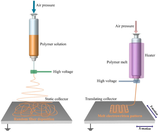
Figure 1.
Schematic representation of solution electrospinning (left), and melt electrospinning writing (right).
Next sections present a summary of the principles, challenges and recent updates of MEW in tissue engineering applications. In this context, the necessity of implementation of MEW as a part of a hybrid approach and its potential for scaffold fabrication is also discussed.
2. Principles and Challenges of MEW
The general MEW setup includes a high voltage supply, back pressure, material reservoir, and a collector. A heating system that is mostly grounded is integrated as an additional element as compared to SE setup. The syringe or nozzle is heated and connected to a high voltage generator [50,51]. Electrical force, applying pressure, and surface tension are the forces that are applied to the molten polymer jet. By increasing the voltage difference and reaching a threshold value, it will be continuously extruded to the collector with a much smaller diameter than the nozzle [52]. For example, this method could reduce the fiber diameter from tens of microns down to 820 nm [47]. The collector or the syringe head could be movable in different directions [50,53]. One of the complexities of MEW setup is exposing heating element to high voltage electric field and how to put an insulator shield between the heating system and the syringe that was connected to high voltage to prevent any electrical interference [53,54]. Another challenge of applying high voltage to polymer melt is to fabricate a well-ordered structure as the tip-to-collector distance increases. The charge accumulation on the deposited fibers would cause fiber repulsion, which results in structural distortion [55]. However, researchers have melt electrospun scaffolds with 100 layers of filaments [47], and Wunner and his coworkers [41] recently performed a numerical analysis to overcome the repulsion of depositing fiber issue that is caused by the accumulation of excess charge. They could achieve a high-volume structure of more than 7 mm. A further key factor in MEW is the heat and charge distribution in the syringe and nozzle, and between the collector and nozzle, respectively, which determines the viscosity of the polymer and the electric force behavior [43,44,56]. Many parameters as printer’s head/collector speed, electric field, back pressure, temperature, and tip-to-collector distance must be in harmony in order to get a highly ordered filament deposition as “writing”. It is noteworthy to mention that the MEW setup itself plays an important role and, since the process is in its infancy, many efforts have provided setup modifications for better control and feasibility of the process to reach perfect structures. Heating components other than electrical heating jackets can be classified into heating guns [57,58], lasers [59,60], and circulating fluids (water and oil) [61] that were used to circumvent the possible difficulties of electrical shortcuts between the heater and electrical fields [41]. In order to apply pressure, the majority of studies used a pneumatic system in their setup with higher control on the applying force [51], rather than that syringe pump [62], screw-extruding, and mechanical feeding [46,63]. The collectors are also divided into two general categories as static [53] and rotating [43]. The rotating cylindrical collectors enable various types of geometries, like tubular structures [3,64,65]. In addition, some pattern shaped collectors were defined to guide the filament deposition in a porous hollow assembly [66].
So far, other setups for ME have been proposed to overcome technical issues or improve the system. For instance, Fang et al. [67] prepared a needleless melt electrospinning setup to avoid the corona discharge issue with the ability to increase the voltage difference up to 90 kV. Morikawa and coworkers [68] established a new setup as wire melt electrospinning and a down-stream non-isothermal heating method as an extra heating source for melt electrospinning in order to reduce the fiber diameter [69]. Another method called bubble melt electrospinning was proposed by Li et al. [70] to eliminate the needle and reduce the fiber diameter. Besides, a research group prepared an umbellate spinneret for mass production reason, rather than applying multiple nozzles [71].
Based on previously mentioned information, the processing parameters, such as collector speed and air pressure, significantly affect final structure and fiber diameter, as represented in Figure 2 [72]. The scaffold’s architecture directly controls its mechanical and biological properties [53,73,74,75]. Therefore, a significant amount of research in the literature has been focused on adjusting, understanding, and predicting the influence of process parameters on fiber diameter, experimentally, and numerically [42,53,62,73,76,77,78,79].
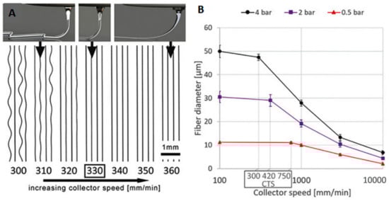
Figure 2.
The effect of collector speed (A) on final structure at constant pressure, and (B) on fiber diameter at different air pressures [72] Copyright 2018 by Wiley-VCH Verlag GmbH & Co. KGaA Weinheim. Reprinted by permission of John Wiley and Sons.
3. Opportunities for MEW in Tissue Engineering
MEW is a recent milestone in additive manufacturing techniques for scaffold fabrication. Applying different biocompatible and biodegradable materials enables great opportunities for a wide range of applications in tissue engineering [4,80] including scaffolds for soft tissues like skin [81], endosteum [82], nerve [83], and cardiac tissue engineering [84]. Tubular structures that showed promising results for different tissues from bone, neural, and vascular applications were also fabricated with the MEW method [64,65].
A wide range of polymers has been used in ME for tissue engineering applications. Polycaprolactone (PCL) [50,66], polylactic acid (PLA) [85], poly-l-lactic acid (PLLA) [86], poly (ethylene glycol) (PEG) [62], polyurethane (PU) [87], polymethyl methacrylate (PMMA) [88], polypropylene (PP) [89], and their blends are the most commonly reported materials. So far, some novel polymers were implemented in this field as well to address the disadvantages of mostly used polymers, like hydration and hydrophobicity. However, polymers in exposure to water-containing environments as culture medium would absorb a considerable amount of water, and consequently lose their mechanical properties. To address this issue, Chen et al. [90] synthesized poly (l-lactide-co-ε-caprolactone-co-acryloyl carbonate) (poly(LLA-ε-CL-AC)), a photo-crosslinkable terpolymer. Bertlein et al. coated PCL with a hydrophilic hydrogel that increased its hydrophilicity for a long-term duration in a pH-independent strategy [91]. Hochleitner and coworkers [92] manufactured melt electrospun scaffolds from a hydrophilic class of polymers, so-called poly(2-oxazoline)s (POx). They synthesized poly(2-ethyl-2-oxazoline (PEtOx) and then revealed its potential for scaffold fabrication by MEW. Melt electrospinning writing was implemented for another polymer with piezoelectric properties. Florczak et al. [93] applied Poly(vinylidene difluoride) (PVDF) for a melt electrospun fibrous mesh structure with the manipulation of process parameters to achieve a perfect highly-ordered structure.
To date, the number of studies working on MEW with new approaches is significantly increasing [34,94]. Wunner et al. demonstrated the scale-up ability of MEW by the integration of multi-print heads to their setup [95]. Eichholz and Hoey [96] studied the effect of scaffold’s architecture on human skeletal stem cell behavior after optimizing their MEW setup. Different scaffold structures were fabricated in random orientation and controlled fiber patterns. The patterned structures were formed by depositing the fibers with an angle of 90, 45, and 10 degrees of every second layers. The effect of scaffold morphology on mechanical strength and cellular behavior were monitored. The results indicated that structure with 90° showed better mechanical properties, as well as cell spreading and osteogenic differentiation.
Hrynevich et al. [71] regulated the pressure and collector speed in their MEW setup during printing and achieved multimodal and multiphasic gradient scaffolds. Cell spheroids seeded in the scaffolds porosities attached and formed aggregates due to the low fiber diameter of the gradient scaffold and proper interconnectivity. In another study by McMaster and colleagues [97], cell spheroids from adipose-derived stromal cells were seeded on a mesh-like structure. Some ultra-fine threading was printed at the bottom of the scaffold by manipulating the processing parameters in order to hold the cell spheroids. The melt electrowritten scaffold induced the adipogenic lineage differentiation, and it provided an environment to obtain a sheet-like structure. In another study, Hochleitner and colleagues [98] performed melt electrospinning writing to fabricate box-shaped scaffolds for tendon and ligament application. The parameters were adjusted to achieve sinusoidal filaments to resemble the crimped structure of collagen I present in tendons and ligaments. An increase in tensile strength, elastic modulus, and elasticity as compared to straight fibers were observed. Besides these applications, Zeng et al. [99] fabricated microfluidic channels via melt electrospinning writing method. A master mold of PCL as a sacrificial layer was melt electrospun, followed by casting polydimethylsiloxane (PDMS) on the patterned PCL structure and further curing. Afterward, the PDMS layer was removed and inlet and outlet holes were punched. Another PDMS microchannel was bonded to the first layer by applying a hot press. By means of this method, they achieved a microfluidic channel in a straightforward and cost-effective manner with the ability to adjust width and depth of the channels.
The current state of literature highlights the great potential of MEW in different areas of tissue engineering and scaffold fabrications, from hard to soft tissues with a wide range of materials according to the desired properties. Mechanical properties and biological response to the scaffolds could be simply tuned with adjusting the internal architecture. Moreover, since no toxic solvent is used, in situ fabrication of scaffolds for applications, such as wound dressings and bandages, could be realized [57]. The possibility of the incorporation of multi-nozzle setups could also be considered. Expansion of materials library, innovative hardware designs, and hence the ability to deliver more structural diversity make MEW a versatile approach to fabricate microstructures with controlled and desired properties.
The balance between processability, mechanical properties of the scaffolds, and their biocompatibility can be considered as one of the main challenges in the further development of MEW. In this respect, the utilization of other established fabrication technologies together with MEW as a hybrid approach could be a promising strategy to overcome the shortfalls of MEW and broadening its potential. By the aid of a hybrid method, one can fabricate hierarchical structures in order to satisfy cellular and mechanical demand and fulfill the requirements for tissue engineering constructs, while other application criteria, such as mechanical durability and/or processing challenges of specific materials, could be addressed. By this way, a handful of techniques that are based on surface modification and/or inclusion of hydrogels within stiff polymer structures fabricated by MEW would make new opportunities in the field of scaffold fabrication. Although the application of MEW as a part of a hybrid bio-manufacturing strategy is not widely explored at the moment, a critical review on the current state of research in this area can provide insight on the possibilities for development of sophisticated multifunctional structures.
4. Hybrid Melt Electrospinning Writing-Fiber Reinforcement of Hydrogel Constructs
MEW exhibits numerous advantages with the ability to fabricate flexible and highly-controlled geometries at sub-micron levels from several polymeric materials [37,81,100], yet, there are considerable issues to be addressed for their effective use in tissue engineering and regenerative medicine (RM). The main limitation is due to the hydrophobic nature of polymers causing the hindrance of controlled cell-scaffold interaction and organization. The examples of post-processing of scaffolds by plasma or sodium hydroxide (NaOH) treatments have been reported to improve hydrophilicity, but the non-specific adsorption of proteins on the construct still restricts the controlled and hierarchical alignment and thus cellular behavior [101,102,103].
Controlling and tuning the mechanical properties of fabricated scaffold via AM techniques that are comparable to native tissue is another pivotal challenge. For example, complex tissues, such as heart, muscle, cartilage, skin, etc., are soft and flexible structures, but they are tough enough to withstand high stresses without any destruction.
Utilizing MEW in a hybrid fashion has introduced new perspectives and enhanced its potential in terms of mechanical properties and biocompatibility. The hybrid constructs of the MEW scaffolds can be prepared with different approaches, as represented in Figure 3.
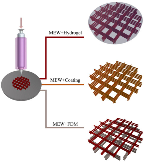
Figure 3.
Different hybrid manufacturing approaches by employing melt electrospinning writing (MEW).
4.1. Reinforcement Mechanism in Melt Electrowritten Fiber-Hydrogel Composites
Hydrogels are excellent candidates for scaffold fabrication with the potential for resembling the microenvironments of human body and encapsulation of different cells in their highly hydrated structures. Their tunable physicochemical properties, such as growth and differentiation factor ingredients, could strongly affect cellular behavior [104,105,106,107]. However, their structures are not as mechanically strong as the ECM of soft tissues, including fibrous proteins. Their lack of mechanical instability also limits the proper cellular functionality. The enhancement of mechanical strength can be achieved by increasing the concentration of polymer content or the crosslinking degree in the hydrogel, which may negatively affect cell viability, proliferation, migration, and differentiation [104,105,106,107,108]. The incorporation of a hydrogel within geometrically varied micro-fibers produced by MEW has fulfilled the required mechanical properties to mimic the function of fibrous ECM of soft tissues [84,109,110,111,112,113,114,115,116]. Mainly, the construction procedure of hybrid hydrogel-MEW composites has two steps, which are the fabrication of fibers via MEW and infiltration of hydrogel in manufactured fibers [84,109,110,111,112,113,114,115,116,117].
The mechanism behind reinforcement of hydrogel matrices by melt electrowritten fibers was investigated in different studies with several hypotheses. Visser et al. [109] elucidated the reinforcement mechanism while using gelatin methacrylate (GelMA) hydrogel infiltrated into highly arranged networks of PCL microfibers. The composite was manufactured for musculoskeletal tissue engineering application, and the reinforced structure showed a significant increase in stiffness compared to hydrogel structure. It was revealed that the reinforced structure’s mechanical strength was similar to that of native cartilage tissue. The hydrogel reinforced with fiber structure showed higher stiffness, rather than hydrogel scaffold and, interestingly, higher than the fiber scaffold without hydrogel. This result demonstrated the synergistic effect of reinforcing the composites. Mainly, lateral expansion of the hydrogel leads to the conversion of axial loads into lateral loads, which can be covered by fiber networks as tension in hybrid composites. Therefore, an increase in stiffness of the composite was correlated with horizontal expansion of the hydrogels while applying stress to the neighboring fibers under tension. Moreover, comparing the compressive loading responses also assessed the effect of fiber diameter on the stiffness of the composites. Low and high fiber diameter networks were manufactured via MEW and FDM, respectively. The composite structure with high fiber diameter showed similar stiffness with the structure without hydrogel. This means that the axial loads did not cause an elongation of the thick fibers. On the other hand, for the composites with thin fibers, the fibers that were elongated as a response to axial loading and hydrogel supported the structural integrity. In addition, the stiffness difference was observed between the groups of fiber networks with and without hydrogels. These observations indicated that a synergistic reinforcement effect was only observed only in the composites with small fiber diameters that were manufactured via MEW. The stiffness of the composite after compressive loading was further demonstrated through a mathematical model [109]. To calculate construct stiffness, fiber radius, the number of fibers and elastic modulus of the polymer were used as directly proportional variables, while the axial strain of fiber and composite and construct radius were used as reversely proportional ones. The mathematical model revealed that hydrogel expands with axial compressive loading and causes exposure of the MEW fibers to tensile loads. However, theoretical stiffness value was calculated larger than the experimental one. It demonstrates the complexity of theoretical modeling of polymer-hydrogel composites, which demands more in-depth studies.
Bas et al. stated a similar hypothesis for reinforcement mechanism of hydrogels by MEW fiber network [48]. As stiffness of the composite relies on the MEW fiber networks, a detailed study was performed by controlling fiber spacing of 400 µm and 800 µm, and grid patterns with 0–90° and 0–60–120° orientations. The constructed melt electrowritten PCL fiber networks were infiltrated with GelMA, and GelMA/hyaluronic acid-methacrylamide (HAMA) hydrogels and the stiffness of the structures were evaluated. It was proposed that the hydrogels had significant lateral to axial strain ratio due to high Poisson’s ratio values. However, the composites showed low Poisson’s ratio, since highly organized fiber networks suppressed lateral deformation of the hydrogels. This synergistic reinforcement mechanism was the same as that reported by Visser et al. [109].
In another study, the high order finite element method was used to simulate the mechanical characteristics and elastic modulus of composites [110]. Composites with varying fiber spacing were used for the analysis. Simulation analysis revealed that decreasing the fiber spacing increased the compressive moduli of the composite due to higher reinforcing filler ratio, which was a similar synergistic reinforcement mechanism with the aforementioned studies [48,109]. The simulation results presented higher stiffness value for fiber networks as compared to experimental data, although the experimental and theoretical data for hydrogel alone and fiber-reinforced hydrogel samples were similar.
Castilho et al. performed two different finite element (FE) analyses in order to investigate the mechanism behind the reinforcement of hydrogel through fiber networks [111], as summarized in Figure 4. In this regard, melt electrowritten PCL network with different fiber spacing and GelMA hydrogel were manufactured. Subsequently, a compression test was performed to obtain stress-strain data that were used as an input for FE analysis. Afterward, a melt electrowritten fiber network was manufactured, and GelMA hydrogel was infiltrated into its gaps, and the FE analysis results were validated with experimental data. In the first analysis, continuum FE model was examined by employing the idealized geometry of the composite, which is unidirectional lamina. Continuum FE model exhibited the expansion of hydrogel inside the composite. Besides, the diminishing effect of fiber network on hydrogel movement was observed. For individual hydrogel and fiber network structures, continuum the FE model results were similar to the experimental data in terms of compressive stress-strain behaviors. However, theoretical stiffness of the composite with higher fiber volume fraction was significantly lower than the experimental data in this model, although the stiffness values for composites with lower fiber volume fraction were similar.
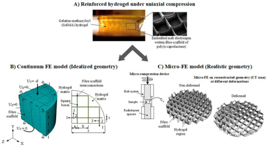
Figure 4.
General modeling overview for continuum and micro-finite element (FE) models. (A) Uniaxial compression test for the investigation of reinforcement mechanism of the composite. (B) Continuum FE model on a quarter of an idealized composite architecture (C) Schematic µ-CT representation of the micro-FE model for the real composite architecture at different deformation levels. (From reference [111], reprinted with permission from Springer Nature).
In second analysis, micro-FE model was performed by employing the micro-computed tomography (µ-CT) images of the composite’s geometry. The micro-FE model presented similar results with the experimental data in terms of deformation of fiber scaffold and composites. The results indicated that addition of hydrogel into fiber scaffold increased stiffness of the overall composite several folds due to the prevention of fiber network buckling through the resistance of hydrogels. Several inferences were made from those FE models. Continuum FE model stated that the reinforcement of the composites with low fiber fraction volume was governed by lateral expansion of the hydrogel, which put the fibers under tension. This hypothesis was similar to the previously mentioned studies. However, those studies did not consider different fiber spacing while explaining the mechanism. On the other hand, micro-FE model underlined the significance of load transfer through the interconnecting regions of the fibers. Reinforcement of the composites with high fiber volume fraction through buckling inhibition by the resistance of hydrogels was also highlighted. Thus, FE analysis would be effective in optimizing the structure’s architecture based on desired mechanical properties.
As an alternative to the heuristic approach, which relies on experimental trials, numerical modeling could be employed for design of the architecture and optimization of manufacturing parameters. In this regard, Bas et al. introduced the design of soft network composite with different mechanical and biological characteristics by modeling and manufacturing the composite, accordingly [112]. By provided compressive modulus and Poisson’s ratio value of the hydrogel as an input to numerical model, compressive modulus of the composite was calculated. Based on the numerical results, 0–90° grid patterns with varying pore size and fiber thickness were determined for the fiber network design. Theoretical compressive modulus value obtained from the numerical model was validated by comparing the experimental results with that of different zones of the articular cartilage tissue model having different mechanical features. For this aim, the PCL fiber network with different fiber thicknesses and pore size was manufactured via MEW, and GelMA hydrogel was filled within the scaffold gaps, as shown in Figure 5. The initial layers of scaffold were printed with the PCL fibers, including hydroxyapatite nanoparticles (nHA), in order to mimic calcified zone, which is present between the native articular cartilage tissue and subchondral bone. Reinforcement of the hydrogels by fiber network was determined through uniaxial compression test. Compressive modulus values obtained by numerical modeling were in agreement with the experimental mechanical testing results.
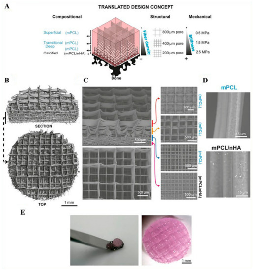
Figure 5.
(A) Schematic view of the designed composite for cartilage application tissue having a different composition, geometry, and mechanical properties. (B) Micro-CT images of PCL fiber networks. (C) Scanning electron microscopy (SEM) images showing different zones of the composite scaffold. (D) SEM images of polycaprolactone (PCL) fibers with and without hydroxyapatite nanoparticles (nHA). (E) General view of the composite structure. Reprinted from [112] Copyright (2018) with permission from Elsevier.
4.2. Biological and Mechanical Aspects of Reinforced Composites in Different Tissue Engineering Applications
Depending on mechanical requirements of the target tissue, such as stress-strain relations, anisotropy, viscoelasticity, and flexibility, different improvements have been made on the MEW fiber-hydrogel composite. Within this framework, fiber networks with varying polymer types, fiber thicknesses, fiber spacing, and geometries have been designed and combined with several hydrogels for different tissue engineering applications.
In a simple approach, MEW PCL scaffold’s porosity and crosslinking degree of GelMA was evaluated based on the composite stiffness and recovery for articular cartilage tissue [109]. Chondrocytes that were encapsulated within GelMA hydrogel were homogeneously distributed throughout the PCL construct. The cells kept their spherical morphology and showed enhanced viability within the reinforced GelMA hydrogels. According to quantitative reverse transcriptase-polymerase chain reaction (PCR) analysis, a physiological compressive loading of 20% strain and 1 Hz induced the up-regulation of expression of genes encoding the ECM proteins of chondrocyte.
In another study, to recapitulate viscoelastic and stress relaxation characteristics of the articular cartilage, high negatively charged star-shaped poly(ethylene glycol)/heparin (sPEG/Hep) was used as hydrogel and then reinforced with the PCL fiber network having a 0°–90° grid pattern with different pore sizes that emulated collagen fibers in terms of anisotropic and nonlinear features [110]. Treating the surface with NaOH treatment increases the wettability of the fiber network.
When compared to alone sPEG/Hep hydrogel and MEW fiber network, the compressive modulus was several folds higher in fiber-reinforced hydrogel composite. Since the compressive modulus of the composite was measured as being higher than the summation of compressive modulus of hydrogel and fiber network alone, which indicated the synergistic reinforcement effect. Moreover, composite structure exhibited similar viscoelastic nature of the articular cartilage. Similar to the results of compressive modulus, only the fiber-reinforced hydrogel composite exhibited similar stress-relaxation behavior with the human articular cartilage, and the enhancement of ECM protein expression under hydrostatic pressure was observed [110].
Another study that was related to articular cartilage tissue engineering was conducted by employing reinforcement of hydrogels through melt electrowritten bi-layered microfiber network [113]. Different zones of articular cartilage tissue were resembled by two layers designed with different fiber patterning strategy in order to obtain zonal mechanical characteristics of the native cartilage tissue. The GelMA hydrogel was cast into the PCL fiber network, which was made up of dense structure with 0–45–90–135° crossed diagonal pattern mimicking a superficial tangential zone (STZ) and uniform 0–90° box structure mimicking middle and deep zone (MDZ) of the articular cartilage. A significant mechanical strength difference was observed between the reinforced and non-reinforced hydrogel structures. The presence of a STZ layer enhanced the compressive modulus several folds as compared to the composite without STZ layer as the presence of STZ layer provided distribution of compressive load to the whole composite uniformly. Human chondrocytes encapsulated in GelMA hydrogel reinforced with bi-layered PCL fibers were tested under two different conditions: static conditions with chondrogenic differentiation factor and mechanical strength induced condition without addition of any differentiation factor. The results revealed that both conditions showed cartilage differentiation by the similar production of sulfated glycosaminoglycan (GAG) and collagen II, which indicated the activation of signaling factors under proposed mechanical condition.
The reinforcement of hydrogel by fiber networks was also used for a variety of other soft tissues. Fiber networks with different geometries have been constructed to meet the requirements of different mechanical properties of soft tissues. For instance, since soft tissues function under high tensile loads, a flexible soft tissue bearing high tensile loads were manufactured by embedding stretchable curvy PCL fiber networks into a hydrogel for tensile load-bearing, mechanical anisotropy, and flexibility [114]. A combination of poly (ethylene glycol) diacrylate (PEGDA), GelMA, and alginate were employed as hydrogel matrix. Since the transfer of the applied loads depends on the interaction between soft matrix and reinforcing fibers, the surface of the fibers was functionalized by photo-crosslinkable acryl groups, which provided covalent bonding between fiber network and PEGDA and GelMA hydrogels. The maximum tensile strain value that the composite could handle before irreversible deformation was recorded as being similar to the values of native soft tissues. After yielding point, manufactured fiber network elongated rather than being ruptured. Stiffness of the composite was several folds higher than the stiffness of hydrogel without reinforcement. Encapsulating human bone-marrow-derived mesenchymal precursor cells (hBMPCs) into the hydrogel assessed the biocompatibility of the soft network system. The encapsulated cells infiltrated into the curvy PCL MEW fibers were found to be viable after 72 h of incubation period.
Cardiac tissue is another complex soft tissue with a highly organized fibrillar structure and mechanical strength. MEW manufacturing method offers great potential to establish an environment with a highly organized structure for cardiac tissue engineering by providing sufficient mechanical strength. Based on this idea, Castilho et al. systematically investigated the effect of hydrophobicity and the morphology of melt electrowritten PCL fibers on collagen reinforcement and the response of cardiac progenitor cells (CPCs) for potential therapeutic applications [84]. Due to the drawbacks of PCL, such as hydrophobic nature and slow degradation, hydroxyl-functionalized polyester, (poly (hydroxymethylglycolide-co-ε-caprolactone) (pHMGCL) was employed. Fiber scaffolds with rectangle and square geometries were manufactured while using two different formulations of polymers, which are PCL and pHMGCL-PCL blend. The fibrous scaffolds were evaluated with and without hydrogel forms. In case of fibrous networks without hydrogel, the tensile modulus of the blended-PCL scaffold was lower than that of scaffolds manufactured from PCL, but both types of scaffolds were in the similar range with the tensile modulus of human myocardium. However, those scaffolds showed different tensile modulus values that were based on their shapes. The rectangular shape exhibited anisotropic behavior of the native cardiac tissue. Even though tensile modulus and anisotropy of the scaffold showed almost similar mechanical characteristics to the native cardiac tissue, long-term mechanical features need to be investigated by employing cyclic tensile loading and other mechanical tests. In the case of composite structures, both blended and bare-PCL scaffold allowed collagen matrix infiltration in a uniform distribution, while collagen hydrogel with no support of PCL fiber scaffold remodeled into a clumped form. The analysis of CPCs in collagen hydrogel within both of the fiber scaffolds that were made up of PCL with and without blending with pHMGCL showed that the cells were 99% viable, regardless of the geometry and hydrophobicity of the fibers. However, cellular alignment and morphology changed, depending on geometry of the scaffold. Cells were randomly arranged in squared geometry scaffolds while the alignment of the cells was more regular, particularly in a preferential direction on rectangular ones. The number of aligned cells on the blended-PCL scaffold was found more than PCL scaffold, as shown in Figure 6. The nucleus of CPC’s in the rectangular blended-PCL composites promoted less circular shape when compared to those in the square-shaped ones. In addition, it was observed that the interconnected porous structure also allowed the interaction of the cells between the compartments. This study revealed that hydrophobic nature of fibers and geometry of the scaffold strongly affect the interference between matrix and reinforcing fibers, which is reflected by cellular behavior. The authors also noted that pHMGCL might change the electrical stimulation on the fibers, which can also have a positive effect on CPC’s response.
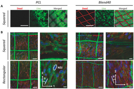
Figure 6.
(A) Viability and (B) morphology of cardiac progenitor cells (CPCs) in collagen hydrogel infiltrated in squared and rectangular bare-PCL and blended-PCL scaffolds [84] Copyright 2017 by Wiley-VCH Verlag GmbH & Co. KGaA Weinheim. Reprinted by permission of John Wiley and Sons.
A physiologically relevant 3D environment that was fabricated from melt electrowritten fibrous composite could be considered for treatment of myocardial regeneration. Generally, the treatment can be followed by replacement of the died cells during myocardial infarction with the healthy cells. Since induced-pluripotent stem cells (iPSCs) have the capability of generating large numbers of human cardiomyocytes, they are the target for direct transplantation, which showed promising results in non-human primates. However, they are not effective due to limited contractility and electrical instability.
Complex fibrillar architecture and mechanical characteristics of myocardial tissue were intended to be recapitulated for the production of heart patch in another study of Castilho et al. [118]. For this purpose, fiber networks with the hexagonal and rectangular structure were manufactured via MEW and then seeded with human induced pluripotent stem cell-derived cardiomyocytes (iPSC-CM), which was encapsulated within a collagen-based hydrogel matrix. Under in-plane tensile loading conditions, biaxial deformation characteristic of the hexagonal fiber scaffold was found to be superior to the rectangular-shaped scaffold. Although the results were better than the rectangular fiber scaffold, deformation, and fatigue behavior of the hexagonal fiber network was poor in the y-direction. The fatigue behavior of the hexagonal fiber scaffold after cyclic tensile loading was more promising than the one in the case of the rectangular fiber network. IPSCs encapsulated in a collagen-based hydrogel were used to monitor the effect of different geometrical composite structures on cellular behavior. The cells were aligned through the fibers and they showed synchronous contractions throughout the scaffold. The cells in the hexagonal fiber network showed faster contractions and maturation of contractile myocytes. In vivo studies followed by injection of the maturated cardiac patch onto a beating, the porcine heart did not reveal harmful effects on cell viability and on integrity of the engineered construct. It was proposed that fabrication of PCL fiber network with hexagonal microstructure improved the biaxial deformation and compliance.
Another different biomimetic design and fabrication strategy was proposed for heart valve tissue engineering (HVTE) in the study carried out by Saidy et al. [116]. The biomechanical characteristics of heart valve leaflets were aimed to be achieved by highly organized wavy-like PCL melt electrowritten fiber scaffold to mimic the collagen fibers that are present in the structure of the heart valve. Human vascular smooth muscle cells (HUVSMCs) were seeded to the scaffold either directly onto the scaffold or by encapsulating in fibrin hydrogel, followed by casting to the scaffold. The mechanical features of the manufactured construct showed similar results with native tissue in terms of J-shaped stress-strain curve behavior, anisotropy, and viscoelasticity. HUVSMC in the homogenously formed composite sustained the viability and exhibited the biochemical and mechanical properties of the main ECM component of native heart valve leaflet with the enhanced synthesis of collagen type I and type III. In the aforementioned studies on cardiac tissue engineering, uniaxial tensile tests were only performed on the fiber scaffolds without hydrogel matrix. Although it would be speculated that the main contributor to the mechanical properties of the composite is fiber network, investigation of the fiber network with hydrogel matrix due to the synergistic effect of the hybrid structure would reveal valuable understanding.
There are other reports that consist of melt electrowritten fibers and hydrogel composites. In those studies, although their potential to recapitulate tissue functions was reported, their mechanical properties were not explored. For example, Hutmacher et al. presented an approach for periosteum regeneration [118]. Periosteum, which is the reservoir for vascular components, and bone-forming cells has a critical role in the regeneration of complex multiphasic system. The periosteum is mechanosensitive tissue that is exposed to shear and traction loads during movement and based on the subjected force it regulates cell proliferation and differentiation. This multiphasic structure was mimicked as in a composite of melt electrowritten PCL tubular scaffold seeded with human bone marrow mesenchymal stem cells (BM-MSCs) and sPEG/Hep hydrogel system that was loaded with human umbilical vein endothelial cells (HUVECs) as a target for large bone defect repair. BM-MSCs were used as bone-forming cells, while the HUVECs cells were utilized for vessel formation. sPEG/Hep hydrogels were modified with RGD and loaded with VEGF. After the hydrogel infiltration in the tubular PCL scaffold, the cells were cultured in angiogenic conditions for seven days of in vitro culturing. Subsequently, the composites were implanted in femur side of mice. The explanted constructs after 30 days from implantation showed that HUVEC cells were not proliferated, but formed capillary-like structures and BM-MSC kept proliferation without differentiation. In addition, it was observed that the implanted human cells were gradually replaced by the host cells. This study demonstrated the efficiency of multiphasic hybrid design with a combination of different human cell types in the periosteum tissue engineering concept.
In another study, the effect of the composition of soft matrix component and photoinitiator type for crosslinking within PCL microfibers on the re-differentiation of chondrocyte was investigated [119]. GelMA type A or type B that were mixed with hyaluronic acid (HA) were photocrosslinked with either lithium acylphosphinate (LAP-visible light; 405 nm) or Irgacure 2929 (IC2929-at UV light; 365 nm). Interestingly, it was found that PCL fiber reinforcement increased the expression of ECM components of chondrocytes in hydrogel constructs. GelMA from type B photocrosslinked with IC2929 enhanced the formation of cartilage-like tissue as compared to others through promoting increased GAG production, which showed similar compressive strength as native articular cartilage.
The MEW-hydrogel hybrid manufacturing approach has also allowed for the development of 3D in vitro tissue models, such as neural and tumor cultures [117,120]. For example, Glycine receptor transfected (GTR; ligand-gated ion channel) Ltk-11 cells encapsulated in Matrigel reinforced with melt electrowritten PCL scaffold. This model provided information regarding the functioning of the ion channels with electrophysiological measurements from a physiologically similar 3D system [120]. In another study, patient-derived ovarian cancer cells were encapsulated in PEG hydrogel infiltrated into PCL fiber scaffold. It was used to mimic the tissue environment for the investigation of malignant behavior and tumor-promoting signals [117]. Designed models showed clinically similar gene expression of ovarian cancer with the samples that were obtained from a high-grade serous ovarian cancer patient. These models may be helpful for screening the possible medicines or a combination of therapies and design for other clinical trials.
It is clear that the MEW-hydrogel hybrid system is a promising technique for RM, TE, and disease models, yet two-step fabrication of the hybrid structures limits the control over-structure design and fiber writing. To overcome this limitation, Ruijter et al. assessed a single-step construction approach by MEW of PCL and extrusion bioprinting of eMSC-laden GelMA hydrogel [105]. This approach allowed for the precise deposition of cells in a mechanically stable composite with controlled porosity and pore shape. It was confirmed that the applied high voltage during construction did not affect either the cell viability and metabolic activity or the ability to differentiate toward multiple lineages of eMSC.
5. Other Hybrid Approaches with MEW
Melt electrowritten fibers post-processed with other materials could be classified as hybrid manufacturing. This approach relies on the initial production of MEW scaffold, which is tuned into relatively hydrophilic surface by plasma, NaOH treatment, or polymer coating. Subsequently, these microfibers are basically coated with cell attractive biomaterials, such as calcium phosphate (CaP), collagen, and fibronectin. For example, NaOH treatment to PCL scaffolds causes the formation of carboxyl and hydroxyl groups, which allows for the reproducible CaP coating. CaP coated fibers showed successful attachment of cells, and the results were found promising for bone tissue engineering [82,121]. Thibaudeau et al. proposed the utilization of the CaP coated PCL melt electrowritten fibers to develop a human bone environment in a murine host model to monitor the metastasis of human breast tumor to bone tissue [121]. The primary human osteoblast cells (hOB) successfully attached on the hybrid structure for seven days, which was then successfully implanted into immunodeficient mice. Afterwards, the formation of humanized bone ossicles in mice was confirmed. After the injection of human breast cancer cells into blood circulation of the mice, it was observed that the cancer cells metastasized and formed lesions on bone tissues. This proposed model system was suggested to be useful for investigating the mechanism of human breast cancer metastasis to human bone in a murine host. In another study, the formation of endosteal bone-like tissue, which has an important role in hematopoietic stem cell proliferation, migration, and differentiation found in the inner wall of long bones surrounding bone cavity on CaP coated MEW PCL scaffolds were demonstrated [82]. The expression of endosteal and osteogenic specific markers of both primary human osteoblasts and placenta-derived mesenchymal stem cells under non-osteogenic and osteogenic conditions demonstrated a realistic design of tissue engineering strategies with physiologically relevant 3D porous ECM microenvironment for the generation of tissue-specific niches.
Bertlein et al. [91,122] fabricated melt electrowritten PCL composites by further coating with proteins and monitored the enhancement of cell attachment and cell functioning. Besides, the relation between the pore size and formation of neovascular like structures was analyzed while using melt electrowritten structures with 100, 200, and 350 µm pore size coated with fibronectin [122]. Figure 7 shows HUVECs attachment on the coated fiber networks after one day incubation period. The formation of a neovascular structure was observed after one week incubation of HUVEC cells on 350 µm pore size scaffolds. In the other study, collagen-functionalized star-shaped polyethylene oxide based prepolymers (sP(EO-stat-PO)) coated PCL scaffolds showed decreased cell attachment, due to a decrease in the non-specific protein adsorption on the surface [91].
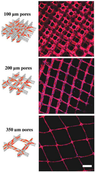
Figure 7.
Attachment of human umbilical vein endothelial cells (HUVECs) on the fibronectin coated PCL fiber networks with different pore size. Scale bar represents 200 µm [122] Copyright 2018 by Wiley-VCH Verlag GmbH & Co. KGaA Weinheim. Reprinted by permission of John Wiley and Sons.
MEW is used in combination with other scaffold generation methods to enhance their biological and mechanical properties. It was combined with FDM to generate a roughened surface that enhanced initial attachment, proliferation, and Ca2+ deposition of the osteoblast-like cells [123]. In another study, melt electrowritten structures with different geometries were designed for attachment of osteoblasts on one side, and keratinocytes and connective tissues on the other side. The fibrous structures were combined with a core PCL film that was prepared via casting to prevent possible infections for applications of oral and maxillofacial surgery [124]. In this study, the design of construct was found cytocompatible with improved cell proliferation and showed bacteria-tightness over two weeks.
Melt electrospun scaffolds could be functionalized by integrating with solution electrospinning [125,126]. In the study of Park et al., they combined MEW with solution electrospinning to acquire micro-nano fibers, mimicking the ECM structure for further application in tissue engineering [125]. PCL was utilized for MEW process to manufacture a mesh-like structure, and a PCL/collagen blend was used for SE, as shown in Figure 8. The hybrid MEW-SE scaffold was fabricated in a two-step manner. The patterned microlayers were melt electrospun, and PCL/collagen nanofibers were deposited between the layers by electrospinning. Three different combinations of MEW and SE were used with varying the number of PCL/collagen layers. Afterwards, bovine chondrocytes were seeded, and cell adhesion and proliferation were investigated for 10 days of incubation on different hybrid scaffold designs. The results demonstrated that the scaffolds containing more layers of PCL/collagen had 2.5 folds higher cell attachment and 2.7 times more cell number than the melt electrospun PCL scaffold. The amide groups of PCL/collagen nanofibers with improvement in its hydrophilicity with the help of its rough surface and higher surface area enhanced the cell attachment, and the ECM like architecture of the hybrid structure enhanced its cell proliferation.
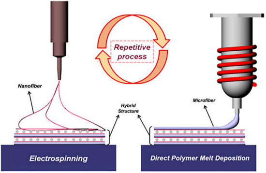
Figure 8.
Hybrid setup of melt electrospinning writing-solution electrospinning (MEW-SE) for manufacturing of composite PCL/collagen structure. Reprinted from [125] Copyright (2008) with permission from Elsevier.
Another study was performed by developing a hybrid MEW-SE setup for neural applications. Khadem Mohtaram et al., melt electrospun two different micro-patterns of PCL as loop mesh and biaxial aligned structures and functionalized them with retinoic acid (RA) encapsulated PCL while using SE. The scaffolds were then seeded with neural progenitors that were derived from human induced pluripotent stem cells (iPSCs). The promotion and differentiation of iPSCs were evaluated, and the effect of different geometries was explored as well. Cell viability, immunohistochemistry, neurite extension, and real-time quantitative PCR analysis were performed. Electrospinning of RA encapsulated PCL increased cell attachment due to expanding the available surface area for cells to adhere. The cells were able to adhere, align, and migrate along the fibers in the loop mesh scaffolds with lower fiber diameters. Biaxial aligned fibers showed more promising results in terms of cell viability, proliferation, elongation, and neurite outgrowth. In general, melt electrospun structures induced the expression of neural markers in the cells, and hybrid structures showed the highest expression of neural markers as compared to loop mesh and biaxial aligned scaffolds. Melt electrospinning could be favorable for neural tissue engineering, since the geometry of the fabricated structure strongly influences the cell alignments and cell response. Moreover, by integrating it with other techniques, it can serve as a promising strategy to fulfill the requirements of the designed scaffold. The modification of melt electrospun structures by solution electrospinning utilizing benign solvents or water with a variety of polymers encapsulated with drugs, nanoparticles, and biomolecules could enrich its application for different tissue engineering purposes.
6. Summary and Future Perspective
The ability to utilize a large number of polymers and their blends has led to an increasing number of studies that are related to MEW in recent years. Computer-controlled nature of the melt electrospinning writing process facilitates design and fabrication of the structures with great control over mechanical properties and, subsequently, cellular responses. Owing to the elimination of solvent in comparison with the solution electrospinning, this method reduces the cost of the process, with respect to the solvent removal and recycling, toxicity and miscibility, and ventilation system. The feasibility of inclusion of several types of nanoparticles and active biomaterials, such as bioactive glasses, carbon nanotubes, drugs, and antibiotics within the polymers has resulted in further expansion of the application of MEW in tissue engineering. Despite the highlighted advantages of MEW, progressive development in material libraries, and establishment of innovative hardware, some requirements are yet to be addressed. For instance, the fiber diameter could not be obtained as low as natural ECM diameter. In addition, most of the polymers that were processed by this method possess hydrophobic surfaces with low control over cell attachment and protein adsorption. Although mechanical properties can be tuned by controlling the structure’s architecture and porosity, high stiffness values, and low elasticities as compared to human tissues are major concerns in further applications. Moreover, the thermoplastic polymers which could be utilized at elevated temperatures are also limited. To address these challenges, the integration of MEW with other techniques as a hybrid process could indeed offer a promising strategy. This integration would, in turn, provide the possibility to include cell-laden hydrogels, heat-sensitive drugs, or bioactive molecules, and to functionalize the polymers with other AM techniques combined with MEW. The reinforcement of hydrogels by well-ordered melt electrospun structures is one of the most common hybrid approaches presented in the literature, which is mainly used for soft tissue regeneration applications. The implementation of rigid polymer meshes within less stiff hydrogels showed significant improvements in composite stiffness. This improvement is explained with the synergistic reinforcement effects with several hypotheses. In general, the residual tensile stress in the fibers due to the expansion of the hydrogel in the compressive loading, enhanced load transfer within the fiber network, and the role of hydrogels in the prevention of buckling have been emphasized. It should be noted that most of the mechanical tests were conducted under compressive loading conditions. However, no investigation on the reinforcement mechanism under other loading conditions (i.e., tensile and shear loading) has been conducted, although they significantly contribute to the mechanical behavior of native tissues. This approach holds high potential in the case of several areas of research, including cartilage, cardiac, neural, skin and bone tissue engineering, and wound healing applications, not only for improving the mechanical properties, but also maintaining a hydrated environment at the same time for cells to attach, migrate, and differentiate. By further development of materials and architectures, we foresee extensive progress in hybrid systems to utilize a wide variety of polymers and hydrogels with several biomolecules, cells, and nanoparticles.
Hybrid approaches are not limited to fiber-reinforced composites. Other approaches, like functionalization or coating of the melt electrospun structures with calcium phosphate, sodium hydroxide, and plasma treatment, were also employed. This would improve the surface properties and tune the functionality of melt electrospun structures for better cell-scaffold interactions. Some researchers developed a hybrid system with other AM or conventional techniques by the incorporation of FDM, solution electrospinning, and casting, into the melt electrowriting setup. This would result in a mechanically strong hydrophilic scaffold with the higher surface area.
As a conclusion, the adjustment of mechanical properties of multiphasic composites can be considered as a key factor in hybrid printing. More comprehensive experimental and numerical modeling studies are needed to better understand the mechanical properties and optimize the properties of hybrid MEW structures. Although elastic modulus and Poisson’s ratio of the components of the hybrid structure would be considered as the main parameters for the modeling studies, other biomechanical features of the components and the mutual interactions of the components should be taken into account to improve the accuracy of modeling.
In addition to the consideration of proper mechanical testing protocols, there exists a gap in the literature regarding the assessment of degradation kinetics of the composites and counterbalance between the extent of degradation and the mechanical and structural integrity. Degradation kinetics and the rate of new tissue formation/integration would play a crucial role in the determination of the interactions between the implanted construct and surrounding tissue after the implantation.
Funding
This research received no external funding.
Conflicts of Interest
The authors declare no conflict of interest.
References
- Howard, D.; Buttery, L.D.; Shakesheff, K.M.; Roberts, S.J. Tissue engineering: Strategies, stem cells and scaffolds. J. Anat. 2008, 213, 66–72. [Google Scholar] [CrossRef] [PubMed]
- Yang, G.H.; Mun, F.; Kim, G.H. Direct electrospinning writing for producing 3D hybrid constructs consisting of microfibers and macro-struts for tissue engineering. Chem. Eng. J. 2016, 288, 648–658. [Google Scholar] [CrossRef]
- Zaiss, S.; Brown, T.D.; Reichert, J.C.; Berner, A. Poly(ε-caprolactone) scaffolds fabricated by melt electrospinning for bone tissue engineering. Materials 2016, 9, 232. [Google Scholar] [CrossRef] [PubMed]
- Dalton, P.D.; Muerza-Cascante, M.L.; Hutmacher, D.W. Design and fabrication of scaffolds via melt electrospinning for applications in tissue engineering. RSC Polym. Chem. Ser. 2015, 2015, 100–120. [Google Scholar]
- Chen, H.; Peng, Y.; Wu, S.; Tan, L.P. Electrospun 3D fibrous scaffolds for chronic wound repair. Materials 2016, 9, 271. [Google Scholar] [CrossRef] [PubMed]
- Intini, C.; Elviri, L.; Cabral, J.; Mros, S.; Bergonzi, C.; Bianchera, A.; Flammini, L.; Govoni, P.; Barocelli, E.; Bettini, R.; et al. 3D-printed chitosan-based scaffolds: An in vitro study of human skin cell growth and an in-vivo wound healing evaluation in experimental diabetes in rats. Carbohydr. Polym. 2018, 199, 593–602. [Google Scholar] [CrossRef] [PubMed]
- Melchels, F.P.W.; Domingos, M.A.N.; Klein, T.J.; Malda, J.; Bartolo, P.J.; Hutmacher, D.W. Additive manufacturing of tissues and organs. Prog. Polym. Sci. 2012, 37, 1079–1104. [Google Scholar] [CrossRef]
- Ahn, S.; Kim, Y.; Lee, H.; Kim, G. A new hybrid scaffold constructed of solid freeform-fabricated PCL struts and collagen struts for bone tissue regeneration: Fabrication, mechanical properties, and cellular activity. J. Mater. Chem. 2012, 22, 15901–15909. [Google Scholar] [CrossRef]
- Hsu, S.H.; Hung, K.C.; Chen, C.W. Biodegradable polymer scaffolds. J. Mater. Chem. B 2016, 4, 7493–7505. [Google Scholar] [CrossRef]
- Zadpoor, A.A.; Malda, J. Additive Manufacturing of Biomaterials, Tissues, and Organs. Ann. Biomed. Eng. 2017, 45, 1–11. [Google Scholar] [CrossRef]
- Giannitelli, S.M.; Accoto, D.; Trombetta, M.; Rainer, A. Current trends in the design of scaffolds for computer-aided tissue engineering. Acta Biomater. 2014, 10, 580–594. [Google Scholar] [CrossRef] [PubMed]
- Ahangar, P.; Cooke, M.E.; Weber, M.H.; Rosenzweig, D.H. Current Biomedical Applications of 3D Printing and Additive Manufacturing. Appl. Sci. 2019, 9, 1713. [Google Scholar] [CrossRef]
- Bose, S.; Ke, D.; Sahasrabudhe, H.; Bandyopadhyay, A. Additive manufacturing of biomaterials. Prog. Mater. Sci. 2018, 93, 45–111. [Google Scholar] [CrossRef] [PubMed]
- Carter, S.S.D.; Costa, P.F.; Vaquette, C.; Ivanovski, S.; Hutmacher, D.W.; Malda, J. Additive Biomanufacturing: An Advanced Approach for Periodontal Tissue Regeneration. Ann. Biomed. Eng. 2017, 45, 12–22. [Google Scholar] [CrossRef] [PubMed]
- Ning, F.; Cong, W.; Qiu, J.; Wei, J.; Wang, S. Additive manufacturing of carbon fiber reinforced thermoplastic composites using fused deposition modeling. Compos. Part B Eng. 2015, 80, 369–378. [Google Scholar] [CrossRef]
- Shofner, M.L.; Lozano, K.; Rodríguez-Macías, F.J.; Barrera, E.V. Nanofiber-reinforced polymers prepared by fused deposition modeling. J. Appl. Polym. Sci. 2003, 89, 3081–3090. [Google Scholar] [CrossRef]
- Hutmacher, D.W.; Schantz, T.; Zein, I.; Ng, K.W.; Teoh, S.H.; Tan, K.C. Mechanical properties and cell cultural response of polycaprolactone scaffolds designed and fabricated via fused deposition modeling. J. Biomed. Mater. Res. 2001, 55, 203–216. [Google Scholar] [CrossRef]
- Lee, K.W.; Wang, S.; Fox, B.C.; Ritman, E.L.; Yaszemski, M.J.; Lu, L. Poly(propylene fumarate) bone tissue engineering scaffold fabrication using stereolithography: Effects of resin formulations and laser parameters. Biomacromolecules 2007, 8, 1077–1084. [Google Scholar] [CrossRef] [PubMed]
- Boland, T.; Xu, T.; Damon, B.; Cui, X. Application of inkjet printing to tissue engineering. Biotechnol. J. 2006, 1, 910–917. [Google Scholar] [CrossRef] [PubMed]
- Kruth, J.P.; Levy, G.; Klocke, F.; Childs, T.H.C. Consolidation phenomena in laser and powder-bed based layered manufacturing. CIRP Ann. Manuf. Technol. 2007, 56, 730–759. [Google Scholar] [CrossRef]
- Li, D.; Xia, Y. Electrospinning of nanofibers: Reinventing the wheel? Adv. Mater. 2004, 16, 1151–1170. [Google Scholar] [CrossRef]
- Xu, T.; Liang, Z.; Ding, B.; Feng, Q.; Fong, H. Polymer blend nanofibers containing polycaprolactone as biocompatible and biodegradable binding agent to fabricate electrospun three-dimensional scaffolds/structures. Polymer 2018, 151, 299–306. [Google Scholar] [CrossRef]
- Xu, T.; Yao, Q.; Miszuk, J.M.; Sanyour, H.J.; Hong, Z.; Sun, H.; Fong, H. Tailoring weight ratio of PCL/PLA in electrospun three-dimensional nanofibrous scaffolds and the effect on osteogenic differentiation of stem cells. Colloids Surf. B Biointerfaces 2018, 171, 31–39. [Google Scholar] [CrossRef] [PubMed]
- Miszuk, J.M.; Xu, T.; Yao, Q.; Fang, F.; Childs, J.D.; Hong, Z.; Tao, J.; Fong, H.; Sun, H. Functionalization of PCL-3D electrospun nanofibrous scaffolds for improved BMP2-induced bone formation. Appl. Mater. Today 2018, 10, 194–202. [Google Scholar] [CrossRef] [PubMed]
- Xu, T.; Miszuk, J.M.; Zhao, Y.; Sun, H.; Fong, H. Electrospun Polycaprolactone 3D Nanofibrous Scaffold with Interconnected and Hierarchically Structured Pores for Bone Tissue Engineering. Adv. Healthc. Mater. 2015, 4, 2238–2246. [Google Scholar] [CrossRef]
- Yao, Q.; Cosme, J.G.L.; Xu, T.; Miszuk, J.M.; Picciani, P.H.S.; Fong, H.; Sun, H. Three dimensional electrospun PCL/PLA blend nanofibrous scaffolds with significantly improved stem cells osteogenic differentiation and cranial bone formation. Biomaterials 2017, 115, 115–127. [Google Scholar] [CrossRef]
- Timnak, A.; Gerstenhaber, J.A.; Dong, K.; Har-El, Y.; Lelkes, P.I. Gradient porous fibrous scaffolds: A novel approach to improving cell penetration in electrospun scaffolds. Biomed. Mater. 2018, 13, 65010. [Google Scholar] [CrossRef]
- Frohbergh, M.E.; Katsman, A.; Botta, G.P.; Lazarovici, P.; Schauer, C.L.; Wegst, U.G.K.; Lelkes, P.I. Electrospun hydroxyapatite-containing chitosan nanofibers crosslinked with genipin for bone tissue engineering. Biomaterials 2012, 33, 9167–9178. [Google Scholar] [CrossRef]
- Lian, H.; Meng, Z. Melt electrospinning vs. solution electrospinning: A comparative study of drug-loaded poly (ε-caprolactone) fibres. Mater. Sci. Eng. C 2017, 74, 117–123. [Google Scholar] [CrossRef]
- Zhang, Y.; Ouyang, H.; Chwee, T.L.; Ramakrishna, S.; Huang, Z.M. Electrospinning of gelatin fibers and gelatin/PCL composite fibrous scaffolds. J. Biomed. Mater. Res. Part B Appl. Biomater. 2005, 72, 156–165. [Google Scholar] [CrossRef]
- Lukáš, D.; Sarkar, A.; Martinová, L.; Vodsed’álková, K.; Lubasová, D.; Chaloupek, J.; Pokorný, P.; Mikeš, P.; Chvojka, J.; Komárek, M. Physical principles of electrospinning (electrospinning as a nano-scale technology of the twenty-first century). Text. Prog. 2009, 41, 59–140. [Google Scholar] [CrossRef]
- Pham, Q.P.; Sharma, U.; Mikos, A.G. Electrospinning of Polymeric Nanofibers for Tissue Engineering Applications: A Review. Tissue Eng. 2006, 12, 1197–1211. [Google Scholar] [CrossRef] [PubMed]
- Brown, T.D.; Dalton, P.D.; Hutmacher, D.W. Melt electrospinning today: An opportune time for an emerging polymer process. Prog. Polym. Sci. 2016, 56, 116–166. [Google Scholar] [CrossRef]
- Zhang, L.H.; Duan, X.P.; Yan, X.; Yu, M.; Ning, X.; Zhao, Y.; Long, Y.Z. Recent advances in melt electrospinning. RSC Adv. 2016, 6, 53400–53414. [Google Scholar] [CrossRef]
- Sun, D.; Chang, C.; Li, S.; Lin, L. Near-field electrospinning. Nano Lett. 2006, 6, 839–842. [Google Scholar] [CrossRef] [PubMed]
- Lee, M.; Kim, H.Y. Toward nanoscale three-dimensional printing: Nanowalls built of electrospun nanofibers. Langmuir 2014, 30, 1210–1214. [Google Scholar] [CrossRef] [PubMed]
- Xu, C.Y.; Inai, R.; Kotaki, M.; Ramakrishna, S. Aligned biodegradable nanofibrous structure: A potential scaffold for blood vessel engineering. Biomaterials 2004, 25, 877–886. [Google Scholar] [CrossRef]
- Wannatong, L.; Sirivat, A.; Supaphol, P. Effects of solvents on electrospun polymeric fibers: Preliminary study on polystyrene. Polym. Int. 2004, 53, 1851–1859. [Google Scholar] [CrossRef]
- Li, D.; Ouyang, G.; McCann, J.T.; Xia, Y. Collecting electrospun nanofibers with patterned electrodes. Nano Lett. 2005, 5, 913–916. [Google Scholar] [CrossRef]
- Lee, J.; Lee, S.Y.; Jang, J.; Jeong, Y.H.; Cho, D.W. Fabrication of patterned nanofibrous mats using direct-write electrospinning. Langmuir 2012, 28, 7267–7275. [Google Scholar] [CrossRef]
- Wunner, F.M.; Wille, M.L.; Noonan, T.G.; Bas, O.; Dalton, P.D.; De-Juan-Pardo, E.M.; Hutmacher, D.W. Melt Electrospinning Writing of Highly Ordered Large Volume Scaffold Architectures. Adv. Mater. 2018, 30, 1706570. [Google Scholar] [CrossRef] [PubMed]
- Zhou, H.; Green, T.B.; Joo, Y.L. The thermal effects on electrospinning of polylactic acid melts. Polymer 2006, 47, 7497–7505. [Google Scholar] [CrossRef]
- Tourlomousis, F.; Ding, H.; Kalyon, D.M.; Chang, R.C. Melt Electrospinning Writing Process Guided by a “Printability Number”. J. Manuf. Sci. Eng. 2017, 139, 081004. [Google Scholar] [CrossRef]
- Ding, H.; Cao, K.; Zhang, F.; Chang, R.C. A fundamental study of charge effects on the melt electrowritten polymer fibers. Mater. Des. 2019, 178, 107857. [Google Scholar] [CrossRef]
- Li, X.; Liu, H.; Wang, J.; Li, C. Preparation and characterization of poly(ε-caprolactone) nonwoven mats via melt electrospinning. Polymer 2012, 53, 248–253. [Google Scholar] [CrossRef]
- He, J.; Xia, P.; Li, D. Development of melt electrohydrodynamic 3D printing for complex microscale poly (ϵ-caprolactone) scaffolds. Biofabrication 2016, 8, 35008. [Google Scholar] [CrossRef] [PubMed]
- Hochleitner, G.; Jüngst, T.; Brown, T.D.; Hahn, K.; Moseke, C.; Jakob, F.; Dalton, P.D.; Groll, J. Additive manufacturing of scaffolds with sub-micron filaments via melt electrospinning writing. Biofabrication 2015, 7, 35002. [Google Scholar] [CrossRef] [PubMed]
- Bas, O.; De-Juan-Pardo, E.M.; Chhaya, M.P.; Wunner, F.M.; Jeon, J.E.; Klein, T.J.; Hutmacher, D.W. Enhancing structural integrity of hydrogels by using highly organised melt electrospun fibre constructs. Eur. Polym. J. 2015, 72, 451–463. [Google Scholar] [CrossRef]
- Lannutti, J.; Reneker, D.; Ma, T.; Tomasko, D.; Farson, D. Electrospinning for tissue engineering scaffolds. Mater. Sci. Eng. C 2007, 27, 504–509. [Google Scholar] [CrossRef]
- Brown, T.D.; Dalton, P.D.; Hutmacher, D.W. Direct writing by way of melt electrospinning. Adv. Mater. 2011, 23, 5651–5657. [Google Scholar] [CrossRef]
- Wei, C.; Dong, J. Direct fabrication of high-resolution three-dimensional polymeric scaffolds using electrohydrodynamic hot jet plotting. J. Micromech. Microeng. 2013, 23, 02501. [Google Scholar] [CrossRef]
- Hutmacher, D.W.; Dalton, P.D. Melt electrospinning. Chem. Asian J. 2011, 6, 44–56. [Google Scholar] [CrossRef] [PubMed]
- Dayan, C.B.; Afghah, F.; Okan, B.S.; Yıldız, M.; Menceloglu, Y.; Culha, M.; Koc, B. Modeling 3D melt electrospinning writing by response surface methodology. Mater. Des. 2018, 148, 87–95. [Google Scholar] [CrossRef]
- Yong Lak, J.; Zhou, H. Apparatus and Method for Elevated Temperature Electrospinning. U.S. Patent No 7,326,043, 5 February 2008. [Google Scholar]
- Wunner, F.M.; Florczak, S.; Mieszczanek, P.; Bas, O.; De-Juan-Pardo, E.M.; Hutmacher, D.W. 5.13-Electrospinning with Polymer Melts—State of the Art and Future Perspectives; Elsevier Ltd.: Amsterdam, The Netherlands, 2017; Volume 5, ISBN 9780128035818. [Google Scholar]
- Sukigara, S.; Gandhi, M.; Ayutsede, J.; Micklus, M.; Ko, F. Regeneration of Bombyx mori silk by electrospinning—Part 1: Processing parameters and geometric properties. Polymer 2003, 44, 5721–5727. [Google Scholar] [CrossRef]
- Qin, C.C.; Duan, X.P.; Wang, L.; Zhang, L.H.; Yu, M.; Dong, R.H.; Yan, X.; He, H.W.; Long, Y.Z. Melt electrospinning of poly(lactic acid) and polycaprolactone microfibers by using a hand-operated Wimshurst generator. Nanoscale 2015, 7, 16611–16615. [Google Scholar] [CrossRef] [PubMed]
- Subramanian, C.; Ugbolue, S.C.; Warner, S.B.; Patra, P.K. The melt electrospinning of polycaprolactone (PCL) ultrafine fibers. Mater. Res. Soc. 2008, 1134. [Google Scholar] [CrossRef]
- Naoki, S.; Tsutsumi, H.; Nakane, K.; Ogihara, T.; Ogata, N. Poly(ethylene-co-vinyl alcohol) and Nylon 6/12 Nanofibers Produced by Melt Electrospinning System Equipped with a Line-Like Laser Beam Melting Device. J. Appl. Polym. Sci. 2010, 116, 2998–3004. [Google Scholar]
- Yang, Z.; Peng, H.; Wang, W.; Liu, T. Crystallization behavior of poly(ε-caprolactone)/layered double hydroxide nanocomposites. J. Appl. Polym. Sci. 2010, 116, 2658–2667. [Google Scholar] [CrossRef]
- Dalton, P.D.; Grafahrend, D.; Klinkhammer, K.; Klee, D.; Möller, M. Electrospinning of polymer melts: Phenomenological observations. Polymer 2007, 48, 6823–6833. [Google Scholar] [CrossRef]
- Detta, N.; Brown, T.D.; Edin, F.K.; Albrecht, K.; Chiellini, F.; Chiellini, E.; Dalton, P.D.; Hutmacher, D.W. Melt electrospinning of polycaprolactone and its blends with poly(ethylene glycol). Polym. Int. 2010, 59, 1558–1562. [Google Scholar] [CrossRef]
- Lyons, J.; Li, C.; Ko, F. Melt-electrospinning part I: Processing parameters and geometric properties. Polymer 2004, 45, 7597–7603. [Google Scholar] [CrossRef]
- Jungst, T.; Muerza-Cascante, M.L.; Brown, T.D.; Standfest, M.; Hutmacher, D.W.; Groll, J.; Dalton, P.D. Melt electrospinning onto cylinders: Effects of rotational velocity and collector diameter on morphology of tubular structures. Polym. Int. 2015, 64, 1086–1095. [Google Scholar] [CrossRef]
- Brown, T.D.; Slotosch, A.; Thibaudeau, L.; Taubenberger, A.; Loessner, D.; Vaquette, C.; Dalton, P.D.; Hutmacher, D.W. Design and fabrication of tubular scaffolds via direct writing in a melt electrospinning mode. Biointerphases 2012, 7, 13. [Google Scholar] [CrossRef] [PubMed]
- Brown, T.D.; Edin, F.; Detta, N.; Skelton, A.D.; Hutmacher, D.W.; Dalton, P.D. Melt electrospinning of poly(ε-caprolactone) scaffolds: Phenomenological observations associated with collection and direct writing. Mater. Sci. Eng. C 2015, 45, 698–708. [Google Scholar] [CrossRef] [PubMed]
- Fang, J.; Zhang, L.; Sutton, D.; Wang, X.; Lin, T. Needleless melt-electrospinning of polypropylene nanofibres. J. Nanomater. 2012, 2012. [Google Scholar] [CrossRef]
- Morikawa, K.; Vashisth, A.; Grimme, C.J.; Green, M.J.; Naraghi, M. Wire Melt Electrospinning of Thin Polymeric Fibers via Strong Electrostatic Field Gradients. Macromol. Mater. Eng. 2019, 304, 1800417. [Google Scholar] [CrossRef]
- Mayadeo, N.; Morikawa, K.; Naraghi, M.; Green, M.J. Modeling of downstream heating in melt electrospinning of polymers. J. Polym. Sci. Part B Polym. Phys. 2017, 55, 1393–1405. [Google Scholar] [CrossRef]
- Li, Y.; Wang, X.; Yu, S.; Zhao, Y.; Yan, X.; Zheng, J.; Yu, M.; Yan, S.-Y.; Long, Y.-Z. Bubble Melt Electrospinning for Production of Polymer Microfibers. Polymers 2018, 10, 1246. [Google Scholar] [CrossRef] [PubMed]
- Li, H.Y.; Bubakir, M.M.; Xia, T.; Zhong, X.F.; Ding, Y.M.; Yang, W.M. Mass production of ultra-fine fibre by melt electrospinning method using umbellate spinneret. Mater. Res. Innov. 2014, 18, S4-921–S4-925. [Google Scholar] [CrossRef]
- Hrynevich, A.; Elçi, B.; Haigh, J.N.; McMaster, R.; Youssef, A.; Blum, C.; Blunk, T.; Hochleitner, G.; Groll, J.; Dalton, P.D. Dimension-Based Design of Melt Electrowritten Scaffolds. Small 2018, 14, 1800232. [Google Scholar] [CrossRef]
- Doustgani, A.; Ahmadi, E. Melt electrospinning process optimization of polylactic acid nanofibers. J. Ind. Text. 2016, 45, 626–634. [Google Scholar] [CrossRef]
- Acatay, K.; Simsek, E.; Ow-Yang, C.; Menceloglu, Y.Z. Tunable, superhydrophobically stable polymeric surfaces by electrospinning. Angew. Chemie Int. Ed. 2004, 43, 5210–5213. [Google Scholar] [CrossRef] [PubMed]
- Boaretti, C.; Roso, M.; Lorenzetti, A.; Modesti, M. Synthesis and process optimization of electrospun PEEK-sulfonated nanofibers by response surface methodology. Materials 2015, 8, 4096–4117. [Google Scholar] [CrossRef] [PubMed]
- Patnaik, A.; Anandjiwala, R.D. An optimized melt spinning process to increase the productivity of nanofiber materials. J. Ind. Text. 2016, 45, 1026–1037. [Google Scholar] [CrossRef]
- Yu, S.X.; Zheng, J.; Yan, X.; Wang, X.X.; Di Nie, G.; Tan, Y.Q.; Zhang, J.; Sui, K.Y.; Long, Y.Z. Morphology control of PLA microfibers and spheres via melt electrospinning. Mater. Res. Express 2018, 5, 45019. [Google Scholar] [CrossRef]
- Zhmayev, E.; Zhou, H.; Joo, Y.L. Modeling of non-isothermal polymer jets in melt electrospinning. J. Nonnewton. Fluid Mech. 2008, 153, 95–108. [Google Scholar] [CrossRef]
- Shen, Y.; Liu, Q.; Deng, B.; Yao, P.; Xia, S. Experimental study and prediction of the diameter of melt-electrospinning polypropylene fiber. Fibers Polym. 2016, 17, 1227–1237. [Google Scholar] [CrossRef]
- Youssef, A.; Hollister, S.J.; Dalton, P.D. Additive manufacturing of polymer melts for implantable medical devices and scaffolds. Biofabrication 2017, 9, 12002. [Google Scholar] [CrossRef]
- Farrugia, B.L.; Brown, T.D.; Upton, Z.; Hutmacher, D.W.; Dalton, P.D.; Dargaville, T.R. Dermal fibroblast infiltration of poly(ε-caprolactone) scaffolds fabricated by melt electrospinning in a direct writing mode. Biofabrication 2013, 5, 25001. [Google Scholar] [CrossRef]
- Muerza-Cascante, M.L.; Shokoohmand, A.; Khosrotehrani, K.; Haylock, D.; Dalton, P.D.; Hutmacher, D.W.; Loessner, D. Endosteal-like extracellular matrix expression on melt electrospun written scaffolds. Acta Biomater. 2017, 52, 145–158. [Google Scholar] [CrossRef]
- Ko, J.; Mohtaram, N.K.; Ahmed, F.; Montgomery, A.; Carlson, M.; Lee, P.C.D.; Willerth, S.M.; Jun, M.B.G. Fabrication of poly (ε-caprolactone) microfiber scaffolds with varying topography and mechanical properties for stem cell-based tissue engineering applications. J. Biomater. Sci. Polym. Ed. 2014, 25, 1–17. [Google Scholar] [CrossRef] [PubMed]
- Castilho, M.; Feyen, D.; Flandes-Iparraguirre, M.; Hochleitner, G.; Groll, J.; Doevendans, P.A.F.; Vermonden, T.; Ito, K.; Sluijter, J.P.G.; Malda, J. Melt Electrospinning Writing of Poly-Hydroxymethylglycolide-co-ε-Caprolactone-Based Scaffolds for Cardiac Tissue Engineering. Adv. Healthc. Mater. 2017, 6, 1700311. [Google Scholar] [CrossRef] [PubMed]
- Qin, Y.; Cheng, L.; Zhang, Y.; Chen, X.; Wang, X.; He, X.; Yang, W.; An, Y.; Li, H. Efficient preparation of poly(lactic acid) nanofibers by melt differential electrospinning with addition of acetyl tributyl citrate. J. Appl. Polym. Sci. 2018, 135, 42–45. [Google Scholar] [CrossRef]
- Xu, H.; Yamamoto, M.; Yamane, H. Melt electrospinning: Electrodynamics and spinnability. Polymer 2017, 132, 206–215. [Google Scholar] [CrossRef]
- Sanders, J.E.; Lamont, S.E.; Karchin, A.; Golledge, S.L.; Ratner, B.D. Fibro-porous meshes made from polyurethane micro-fibers: Effects of surface charge on tissue response. Biomaterials 2005, 26, 813–818. [Google Scholar] [CrossRef] [PubMed]
- Wang, X.F.; Huang, Z.M. Melt-electrospinning of PMMA. Chinese J. Polym. Sci. 2010, 28, 45–53. [Google Scholar] [CrossRef]
- Nayak, R.; Kyratzis, I.L.; Truong, Y.B.; Padhye, R.; Arnold, L. Melt-electrospinning of polypropylene with conductive additives. J. Mater. Sci. 2012, 47, 6387–6396. [Google Scholar] [CrossRef]
- Chen, F.; Hochleitner, G.; Woodfield, T.; Groll, J.; Dalton, P.D.; Amsden, B.G. Additive Manufacturing of a Photo-Cross-Linkable Polymer via Direct Melt Electrospinning Writing for Producing High Strength Structures. Biomacromolecules 2016, 17, 208–214. [Google Scholar] [CrossRef]
- Bertlein, S.; Hochleitner, G.; Schmitz, M.; Tessmar, J.; Raghunath, M.; Dalton, P.D.; Groll, J. Permanent Hydrophilization and Generic Bioactivation of Melt Electrowritten Scaffolds. Adv. Healthc. Mater. 2019, 8, 1801544. [Google Scholar] [CrossRef]
- Hochleitner, G.; Hümmer, J.F.; Luxenhofer, R.; Groll, J. High definition fibrous poly(2-ethyl-2-oxazoline) scaffolds through melt electrospinning writing. Polymer 2014, 55, 5017–5023. [Google Scholar] [CrossRef]
- Florczak, S.; Lorson, T.; Zheng, T.; Mrlik, M.; Hutmacher, D.W.; Higgins, M.J.; Luxenhofer, R.; Dalton, P.D. Melt electrowriting of electroactive poly(vinylidene difluoride) fibers. Polym. Int. 2019, 68, 735–745. [Google Scholar] [CrossRef]
- Muerza-Cascante, M.L.; Haylock, D.; Hutmacher, D.W.; Dalton, P.D. Melt Electrospinning and Its Technologization in Tissue Engineering. Tissue Eng. Part B Rev. 2015, 21, 187–202. [Google Scholar] [CrossRef] [PubMed]
- Wunner, F.M.; Eggert, S.; Maartens, J.; Bas, O.; Dalton, P.D.; De-Juan-Pardo, E.M.; Hutmacher, D.W. Design and Development of a Three-Dimensional Printing High-Throughput Melt Electrowriting Technology Platform. 3D Print. Addit. Manuf. 2018, 6, 82–90. [Google Scholar] [CrossRef]
- Eichholz, K.F.; Hoey, D.A. Mediating human stem cell behaviour via defined fibrous architectures by melt electrospinning writing. Acta Biomater. 2018, 75, 140–151. [Google Scholar] [CrossRef] [PubMed]
- McMaster, R.; Hoefner, C.; Hrynevich, A.; Blum, C.; Wiesner, M.; Wittmann, K.; Dargaville, T.R.; Bauer-Kreisel, P.; Groll, J.; Dalton, P.D.; et al. Tailored Melt Electrowritten Scaffolds for the Generation of Sheet-Like Tissue Constructs from Multicellular Spheroids. Adv. Healthc. Mater. 2019, 8, 1801326. [Google Scholar] [CrossRef] [PubMed]
- Hochleitner, G.; Chen, F.; Blum, C.; Dalton, P.D.; Amsden, B.; Groll, J. Melt electrowriting below the critical translation speed to fabricate crimped elastomer scaffolds with non-linear extension behaviour mimicking that of ligaments and tendons. Acta Biomater. 2018, 72, 110–120. [Google Scholar] [CrossRef] [PubMed]
- Zeng, J.; Wang, H.; Lin, Y.; Zhang, J.; Liang, F.; Fang, F.; Yang, F.; Wang, P.; Zhu, Z.; Chen, X.; et al. Fabrication of microfluidic channels based on melt-electrospinning direct writing. Microfluid. Nanofluid. 2018, 22, 23. [Google Scholar] [CrossRef]
- Schnell, E.; Klinkhammer, K.; Balzer, S.; Brook, G.; Klee, D.; Dalton, P.; Mey, J. Guidance of glial cell migration and axonal growth on electrospun nanofibers of poly-ε-caprolactone and a collagen/poly-ε-caprolactone blend. Biomaterials 2007, 28, 3012–3025. [Google Scholar] [CrossRef]
- Fuchs, A.; Youssef, A.; Seher, A.; Hochleitner, G.; Dalton, P.D.; Hartmann, S.; Brands, R.C.; Müller-Richter, U.D.A.; Linz, C. Medical-grade polycaprolactone scaffolds made by melt electrospinning writing for oral bone regeneration—A pilot study in vitro. BMC Oral Health 2019, 19, 28. [Google Scholar] [CrossRef]
- Yan, D.; Jones, J.; Yuan, X.; Xu, X.; Sheng, J.; Lee, J.C.M.; Ma, G.; Yu, Q. Plasma treatment of random and aligned electrospun PCL nanofibers. J. Med. Biol. Eng. 2013, 33, 171–178. [Google Scholar] [CrossRef]
- Abbasi, N.; Soudi, S.; Hayati-Roodbari, N.; Dodel, M.; Soleimani, M. The effects of plasma treated electrospun nanofibrous poly (ε-caprolactone) Scaffolds with different orientations on mouse embryonic stem cell proliferation. Cell J. 2014, 16, 245–254. [Google Scholar] [PubMed]
- Hollander, A.P.; Dickinson, S.C.; Kafienah, W. Stem cells and cartilage development: Complexities of a simple tissue. Stem Cells 2010, 28, 1992–1996. [Google Scholar] [CrossRef] [PubMed]
- De Ruijter, M.; Ribeiro, A.; Dokter, I.; Castilho, M.; Malda, J. Simultaneous Micropatterning of Fibrous Meshes and Bioinks for the Fabrication of Living Tissue Constructs. Adv. Healthc. Mater. 2019, 8, 1800418. [Google Scholar] [CrossRef] [PubMed]
- Levett, P.A.; Melchels, F.P.W.; Schrobback, K.; Hutmacher, D.W.; Malda, J.; Klein, T.J. A biomimetic extracellular matrix for cartilage tissue engineering centered on photocurable gelatin, hyaluronic acid and chondroitin sulfate. Acta Biomater. 2014, 10, 214–223. [Google Scholar] [CrossRef] [PubMed]
- Drury, J.L.; Mooney, D.J. Hydrogels for tissue engineering: Scaffold design variables and applications. Biomaterials 2003, 24, 4337–4351. [Google Scholar] [CrossRef]
- Kharkar, P.M.; Kiick, K.L.; Kloxin, A.M. Designing degradable hydrogels for orthogonal control of cell microenvironments. Chem. Soc. Rev. 2013, 42, 7335–7372. [Google Scholar] [CrossRef] [PubMed]
- Visser, J.; Melchels, F.P.W.; Jeon, J.E.; Van Bussel, E.M.; Kimpton, L.S.; Byrne, H.M.; Dhert, W.J.A.; Dalton, P.D.; Hutmacher, D.W.; Malda, J. Reinforcement of hydrogels using three-dimensionally printed microfibres. Nat. Commun. 2015, 6, 6933. [Google Scholar] [CrossRef]
- Bas, O.; De-Juan-Pardo, E.M.; Meinert, C.; D’Angella, D.; Baldwin, J.G.; Bray, L.J.; Wellard, R.M.; Kollmannsberger, S.; Rank, E.; Werner, C.; et al. Biofabricated soft network composites for cartilage tissue engineering. Biofabrication 2017, 9, 025014. [Google Scholar] [CrossRef]
- Castilho, M.; Hochleitner, G.; Wilson, W.; Van Rietbergen, B.; Dalton, P.D.; Groll, J.; Malda, J.; Ito, K. Mechanical behavior of a soft hydrogel reinforced with three-dimensional printed microfibre scaffolds. Sci. Rep. 2018, 8, 1245. [Google Scholar] [CrossRef]
- Bas, O.; Lucarotti, S.; Angella, D.D.; Castro, N.J.; Meinert, C.; Wunner, F.M.; Rank, E.; Vozzi, G.; Klein, T.J.; Catelas, I.; et al. Rational design and fabrication of multiphasic soft network composites for tissue engineering articular cartilage: A numerical model-based approach. Chem. Eng. J. 2018, 340, 15–23. [Google Scholar] [CrossRef]
- Castilho, M.; Mouser, V.; Chen, M.; Malda, J.; Ito, K. Bi-layered micro-fibre reinforced hydrogels for articular cartilage regeneration. Acta Biomater. 2019. [Google Scholar] [CrossRef] [PubMed]
- Bas, O.; D’Angella, D.; Baldwin, J.G.; Castro, N.J.; Wunner, F.M.; Saidy, N.T.; Kollmannsberger, S.; Reali, A.; Rank, E.; De-Juan-Pardo, E.M.; et al. An Integrated Design, Material, and Fabrication Platform for Engineering Biomechanically and Biologically Functional Soft Tissues. ACS Appl. Mater. Interfaces 2017, 9, 29430–29437. [Google Scholar] [CrossRef] [PubMed]
- Castilho, M.; van Mil, A.; Maher, M.; Metz, C.H.G.; Hochleitner, G.; Groll, J.; Doevendans, P.A.; Ito, K.; Sluijter, J.P.G.; Malda, J. Melt Electrowriting Allows Tailored Microstructural and Mechanical Design of Scaffolds to Advance Functional Human Myocardial Tissue Formation. Adv. Funct. Mater. 2018, 28, 1803151. [Google Scholar] [CrossRef]
- Saidy, N.T.; Wolf, F.; Bas, O.; Keijdener, H.; Hutmacher, D.W.; Mela, P.; De-Juan-Pardo, E.M. Biologically Inspired Scaffolds for Heart Valve Tissue Engineering via Melt Electrowriting. Small 2019, 15, 1900873. [Google Scholar] [CrossRef] [PubMed]
- Loessner, D.; Rockstroh, A.; Shokoohmand, A.; Holzapfel, B.M.; Wagner, F.; Baldwin, J.; Boxberg, M.; Schmalfeldt, B.; Lengyel, E.; Clements, J.A.; et al. A 3D tumor microenvironment regulates cell proliferation, peritoneal growth and expression patterns. Biomaterials 2019, 190–191, 63–75. [Google Scholar] [CrossRef] [PubMed]
- Hutmacher, D.W.; Wagner, F.; Martine, L.C.; Holzapfel, B.M.; Theodoropoulos, C.; Bas, O.; Savi, F.M.; De-Juan-Pardo, E.M.; Hutmacher, D.W. Periosteum tissue engineering in an orthotopic in vivo platform. Biomaterials 2017, 121, 193–204. [Google Scholar]
- Pahoff, S.; Meinert, C.; Bas, O.; Nguyen, L.; Klein, T.J.; Hutmacher, D.W. Effect of gelatin source and photoinitiator type on chondrocyte redifferentiation in gelatin methacryloyl-based tissue-engineered cartilage constructs. J. Mater. Chem. B 2019, 7, 1761–1772. [Google Scholar] [CrossRef]
- Schaefer, N.; Janzen, D.; Bakirci, E.; Hrynevich, A.; Dalton, P.D.; Villmann, C. 3D Electrophysiological Measurements on Cells Embedded within Fiber-Reinforced Matrigel. Adv. Healthc. Mater. 2019, 8, 1801226. [Google Scholar] [CrossRef]
- Thibaudeau, L.; Taubenberger, A.V.; Holzapfel, B.M.; Quent, V.M.; Fuehrmann, T.; Hesami, P.; Brown, T.D.; Dalton, P.D.; Power, C.A.; Hollier, B.G.; et al. A tissue-engineered humanized xenograft model of human breast cancer metastasis to bone. Dis. Model. Mech. 2014, 7, 299–309. [Google Scholar] [CrossRef]
- Bertlein, S.; Hikimoto, D.; Hochleitner, G.; Hümmer, J.; Jungst, T.; Matsusaki, M.; Akashi, M.; Groll, J. Development of Endothelial Cell Networks in 3D Tissues by Combination of Melt Electrospinning Writing with Cell-Accumulation Technology. Small 2018, 14, 1701521. [Google Scholar] [CrossRef]
- Kim, G.H.; Ahn, S.H.; Lee, H.J.; Lee, S.; Cho, Y.; Chun, W. A new hybrid scaffold using rapid prototyping and electrohydrodynamic direct writing for bone tissue regeneration. J. Mater. Chem. 2011, 21, 19138–19143. [Google Scholar] [CrossRef]
- Fuchs, A.; Youssef, A.; Seher, A.; Hartmann, S.; Brands, R.C.; Müller-Richter, U.D.A.; Kübler, A.C.; Linz, C. A new multilayered membrane for tissue engineering of oral hard-and soft tissue by means of melt electrospinning writing and film casting—An in vitro study. J. Cranio-Maxillofacial Surg. 2019, 47, 695–703. [Google Scholar] [CrossRef] [PubMed]
- Park, S.H.; Kim, T.G.; Kim, H.C.; Yang, D.Y.; Park, T.G. Development of dual scale scaffolds via direct polymer melt deposition and electrospinning for applications in tissue regeneration. Acta Biomater. 2008, 4, 1198–1207. [Google Scholar] [CrossRef] [PubMed]
- Mohtaram, N.K.; Ko, J.; King, C.; Sun, L.; Muller, N.; Jun, M.B.G.; Willerth, S.M. Electrospun biomaterial scaffolds with varied topographies for neuronal differentiation of human-induced pluripotent stem cells. J. Biomed. Mater. Res. Part A 2015, 103, 2591–2601. [Google Scholar] [CrossRef] [PubMed]
© 2019 by the authors. Licensee MDPI, Basel, Switzerland. This article is an open access article distributed under the terms and conditions of the Creative Commons Attribution (CC BY) license (http://creativecommons.org/licenses/by/4.0/).