Article

Predicting the Mechanical Properties of Bimrocks with High Rock Block Proportions Based on Resonance Testing Technology and Damage Theory

School of Civil Engineering, Central South University, Changsha 410075, China
*
Authors to whom correspondence should be addressed.
Appl. Sci. 2019, 9(17), 3537; https://doi.org/10.3390/app9173537
Submission received: 28 July 2019 / Revised: 21 August 2019 / Accepted: 23 August 2019 / Published: 28 August 2019

Abstract

:
Block-in-matrix-rocks (bimrocks) are very complicated geological masses that cause many challenging problems during the design and construction of engineering projects, such as parameter determination and landsliding. Successful engineering design and construction depends on a suitable constitutive model and reliable design parameters for geological masses. In this paper, the vibration attenuation signal of welded bimrocks was obtained and studied using resonance test technology. Combined with a uniaxial compression test, a constitutive model was proposed to describe the mechanical behavior of welded bimrocks. On this basis, the relations between the dynamic elastic modulus and the physical parameters of bimrocks were established, which included macroscopic mechanical parameters and damage constitutive parameters. Consequently, a new technological process was proposed to provide quick identification of the mechanical properties of welded bimrocks. The results indicate that the dynamic elastic modulus is highly correlated with the rock block proportion (RBP) and uniaxial compression strength (UCS). It is an effective parameter to predict the strength of the bimrocks with high RBPs. Additionally, the proposed constitutive model, which is based on damage theory, can accurately simulate the strain softening behavior of the bimrocks. Combining the resonant frequency technology and the proposed constitutive model, the complete stress strain curve can be obtained in a rapid and accurate manner, which provides a further guarantee of the stability and safety of underground engineering.

1. Introduction

Block-in-matrix-rocks (bimrocks) with high rock block proportions (RBPs) are considered problematic geological materials during engineering construction [1,2,3]. Figure 1 illustrates several types of geological formations in nature, which consist of higher RBPs and lower matrix contents. Due to the high block proportions, the physical and mechanical properties of the geological material can be rather different and heterogeneous, which may cause challenging problems for tunnel excavation, dam construction, and slope engineering. Thus, determination of the strength and elastic modulus of such geological materials is fundamental and crucial to guarantee the safety and stability of the aforementioned projects [4,5,6,7,8,9,10,11].
Recently, some studies have been carried out to reveal the feasibility of predicting the strength of bimrocks with high RBPs based on laboratory experiments. Mohammad Afifipour [12,13] conducted a uniaxial compression test on the bimrocks with high RBP ranging from 70% to 90%. The RBP was proven to be an effective parameter to predict the strength and deformation properties. However, the proposed model only considered a single influencing factor; other factors such as matrix strength and rock properties were ignored. Therefore, Sonmez. et al. [14] suggested the use of empirical equations to predict the strength of bimrocks, which depends on multiple input parameters, e.g., RBP, repose angle of rock blocks, and the strength parameters of the matrix. Moreover, A. Kalender [15] calibrated the equations on the basis of experimental data from Lindquist [16], Altinsoy [17], and Coskun [18]. The results showed that the empirical approach has high predictability with slightly conservative errors. Nevertheless, a series experiment process was required to obtain the input parameters. Other than empirical approaches, H. Sonmez also introduced a back-propagation artificial neural network (BP-ANN) to predict the uniaxial compression strength (UCS) and the elastic modulus of bimrocks. However, an enormous database is required to train the network. Although the aforementioned approach provided effective prediction results under different conditions, a more convenient and practical method is preferred on construction sites.
The widely used non-destruction test technology could be a promising solution to predict the strength of bimrocks in an accurate and rapid manner. Mahdevar et al. [19,20] measured the velocity of ultrasonic waves of bimrocks with different RBPs and a multiple regression analysis was performed to correlate the UCS with the wave velocity. Wang et al. [21,22] obtained the complete stress-strain curves under uniaxial compression and the ultrasonic wave velocities of bimrocks with different RBP through indoor tests, and a simple damage constitutive equation of bimrocks was proposed based on the experimental data. Meanwhile, these tests also confirmed that applying ultrasonic testing technology to study the properties of bimrocks is feasible. Sun et al. [23] investigated the damage characteristics and cracking state of bimrocks throughout the entire process of uniaxial compression using digital imaging technology. The results indicated that the damage state of bimrocks has a significant impact on their macro-mechanical properties.
In conclusion, it is an effective and feasible to study the mechanical properties of welded bimrocks through combining the traditional compression test and nondestructive testing techniques, such as ultrasonic testing technology and digital imaging technology [19,20,21,22,23,24]. These methods provide a reliable basis for quickly identifying the mechanical properties of bimrocks [24]. However, at present, few existing studies have linked the vibration attenuation signals of bimrocks to their mechanical properties. Additionally, Medley, who defined the term “bimrocks” and conducted the original research on this special geological body, delimited the RBP of bimrocks as being between 25% and 75% in his research [25]. Most of the existing studies from different approaches adopted the same ranges to study the physical and mechanical properties of bimrocks. [14,19,25]. However, in nature, several kinds of geological formations exist with higher RBPs and low matrix contents, such as cemented talus, mine waste dumps, and cemented rockfill in underground mining [12,13]. Only a few studies have reported the mechanical properties of bimrocks with higher RBPs. In addition, studies on constitutive models of bimrocks are also rare.
In this study, the vibration attenuation signals of welded bimrocks with high rock contents are tested and analyzed using a resonance frequency tester. Combined with the uniaxial compression test and damage constitutive theory, the internal relationships between the vibration response signal of welded bimrocks and their mechanical and constitutive parameters are established, which provides a new solution for fast discrimination of the mechanical properties of welded bimrocks at construction sites.

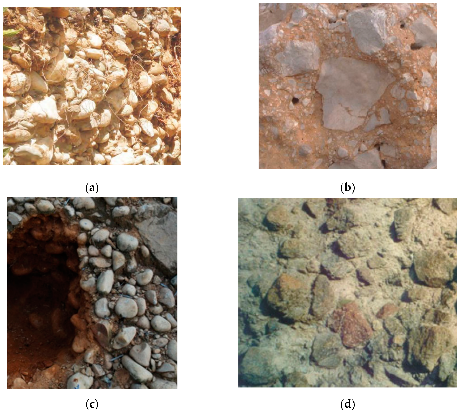
2. Specimen Preparation and Experimental Method

The mechanical properties of welded bimrocks are influenced by various factors such as the block proportion, matrix strength, block gradation, etc. Previous studies proved that the RBP is one of the dominant factors affecting the mechanical properties of bimrocks [19,21,22,26]. Compared to the existing studies, the presented research focused on the mechanical characteristics and properties of bimrocks with higher RBP, ranging from 60% to 90%. Four groups of specimens with different RBPs of 60%, 70%, 80%, and 90% were set for testing, of which the characteristics of the nondestructive signals and macro-mechanical properties were recorded and investigated.
Figure 2 shows the gradation of the blocks. Obviously, to avoid the influences of other factors on the macroscopic mechanical parameters and nondestructive testing signals of bimrocks, all specimens in the test were unified with a continuous gradation of limestone, which is shown in Figure 2. The density and compressive strength of the rock block were approximately 2.68 g/cm3 and 87.32 MPa, respectively. The specimen was a cylinder with a height of 200 mm and a diameter of 100 mm. According to the relevant testing technical standards [27,28], the maximum particle size of a rock block should not be greater than 20 mm so that the scale effect caused by the oversized particles can be avoided. The minimum particle diameter of a rock block, which is the threshold of soil and rock, is 4.75 mm. The matrix was made of P.O. 42.5 cement and dry sand soil (d < 4.75 mm, density 2.65 g/cm3) with a mass ratio of 1:1 and a water–cement ratio of 0.3.
In the process of specimen preparation, dry sand, cement, and rock blocks were poured into the mixing machine in sequence and stirred for 30 s, then water was added in moderation and stirred well. The inner wall of the mold was evenly coated with mineral oil. The mixtures were placed in three approximately equal layers and each layer was subjected to mechanical vibration for 20 s. The specimens were demolded after 24 h. For curing, the specimens were kept in a moist environment at a temperature of approximately 25 °C and a relative humidity of 95% for 7 days. Before the tests, each cylinder specimen was capped at both ends with a gypsum capping compound to ensure that the two ends were planar. Then, the resonance frequency test and uniaxial compression test were carried out. The specimens and test equipment are shown in Figure 3 and Figure 4.
As shown in Figure 4, the E-Meter MK II resonance frequency tester was used to test the vibration response of specimens, which had an accelerometer sensitivity of 9.60 mV/g. The WAW-600 servo-hydraulic testing machine was adopted to test the UCS with a maximum axial force of 600 kN. During the loading process, the loading rate was controlled at 0.3 MPa/s and the test was terminated when the measured stress decreased to 10% of the peak strength.

3. Analysis of Resonance Test Results

Figure 5 shows the test results of the vibration acceleration for specimens containing 60% and 90% rock proportions, respectively.
As shown in Figure 5, the vibration damping rate of bimrocks with a rock proportion of 90% was greater than that of bimrocks with a rock content of 60%. Due to the notable rise in the void structure of bimrocks with a 90% block proportion, it is estimated that the well-developed void structure accelerates the energy dissipation and results in the increase in the vibration damping rate. However, the differences were relatively insignificant and easily affected by the quality of signal acquisition. In contrast, the acceleration resonance frequencies of the specimens with different RBPs showed distinctive differences. Additionally, stable test results were still obtained when the test signal was poor, which could better distinguish the physical and mechanical properties of welded bimrocks. On the basis of the operator’s manual of the resonance frequency tester [29], the acceleration resonance frequency can be converted into a dynamic elastic modulus as follows:
E d y = λ × l × M d 2 ω a 2 ,
where E d y is the dynamic modulus of elasticity, ω a is the acceleration resonance frequency, l is the length of the specimen, d is the diameter of the specimen, M is the mass of the specimen, and λ is the system constant, which is calibrated to 5.093 for a cylinder specimen and 4.000 for a prism specimen [29].
The relation between E d y and R B P is presented in Figure 6. A clear decreasing trend in the dynamic elastic modulus was observed with an increase in the RBP value. An exponential relation was obtained through the method of least square, as shown in Equation (2). According to the test data in Figure 6, the dynamic elastic modulus of each group had limited dispersion due to the strict specimen preparation process, which contributed to the high R 2 in the fit Equation (2). The fit results also indicate that the exponential type function can effectively illustrate the quantitative relation between the dynamic elastic modulus and the RBP. Additionally, the dynamic elastic modulus can be used as an effective index for judging the mechanical properties of welded bimrocks.
E d y = 1.3 · 10 - 5 · exp ( R B P / 0.063 ) + 32.01 ,   R 2 = 0.97 ,

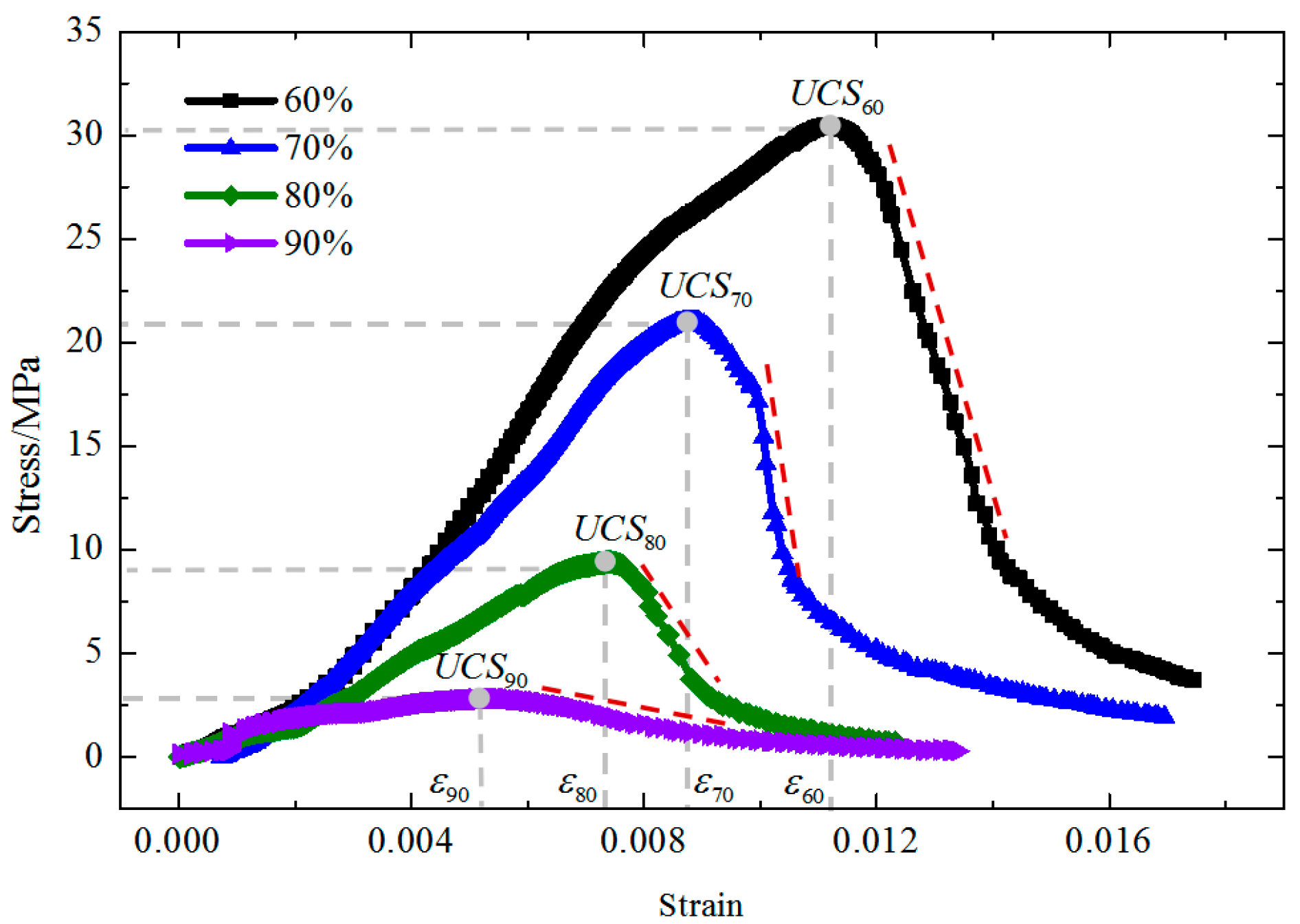
4. Analysis of the Uniaxial Compression Test Results

Figure 7 illustrates the typical stress strain curves of welded bimrocks with different RBPs. The specific values of the UCS were placed in Table 1. As seen in Figure 7 and Table 1, the stress strain relation and mechanical characterization of specimens depend strongly on the RBP. Although the curves shared a similar evolution trend, the peak strength and slope in the pre-peak zone dropped considerably with the increase of RBP. Additionally, the higher block proportion corresponded to a lower failure strain, which, for the sake of simplicity, was defined as the strain at which maximum stress was reached. For the deformation patterns in the post failure region, a sharp decrease of strength was observed in the curves with block contents of 60% and 70%, as shown by the dotted line in Figure 7. However, the ductile behavior was more dominant in the curves with higher RBPs.
Figure 8 shows the relation between the UCS and the RBP of bimrocks. The UCS of bimrocks descended gradually with the increase in RBP. The fit result for the curve in Figure 8 is presented in Equation (3) using the least-squares method. As can be seen, a strong exponential correlation was found between UCS and RBP.
U C S = 237.91 exp ( R B P / 0.37 ) 17.66 ;   R 2 = 0.94 ,
Figure 9 shows the failure morphology of specimens with different rock contents. Vertical cracks through the matrix represent the dominant failure pattern for the specimens with RBPs lower than 70%. The matrix strength was shown to have a strong influence on the UCS of the welded bimrocks within this range of RBPs. The other kind of crack appeared with a further increase in the RBP, which occurred along the interface between the soil and the rocks. The failure pattern was a combination of both splitting and sliding. Thus, the interface strength also affected the UCS of the welded bimrocks. When the rock proportion reached 90%, the UCS of the welded bimrocks was mainly dependent on the interface strength between the soil and rock. The split failure was hard to find under such conditions. In contrast, localized shear failure was observed due to the well-developed void structure.

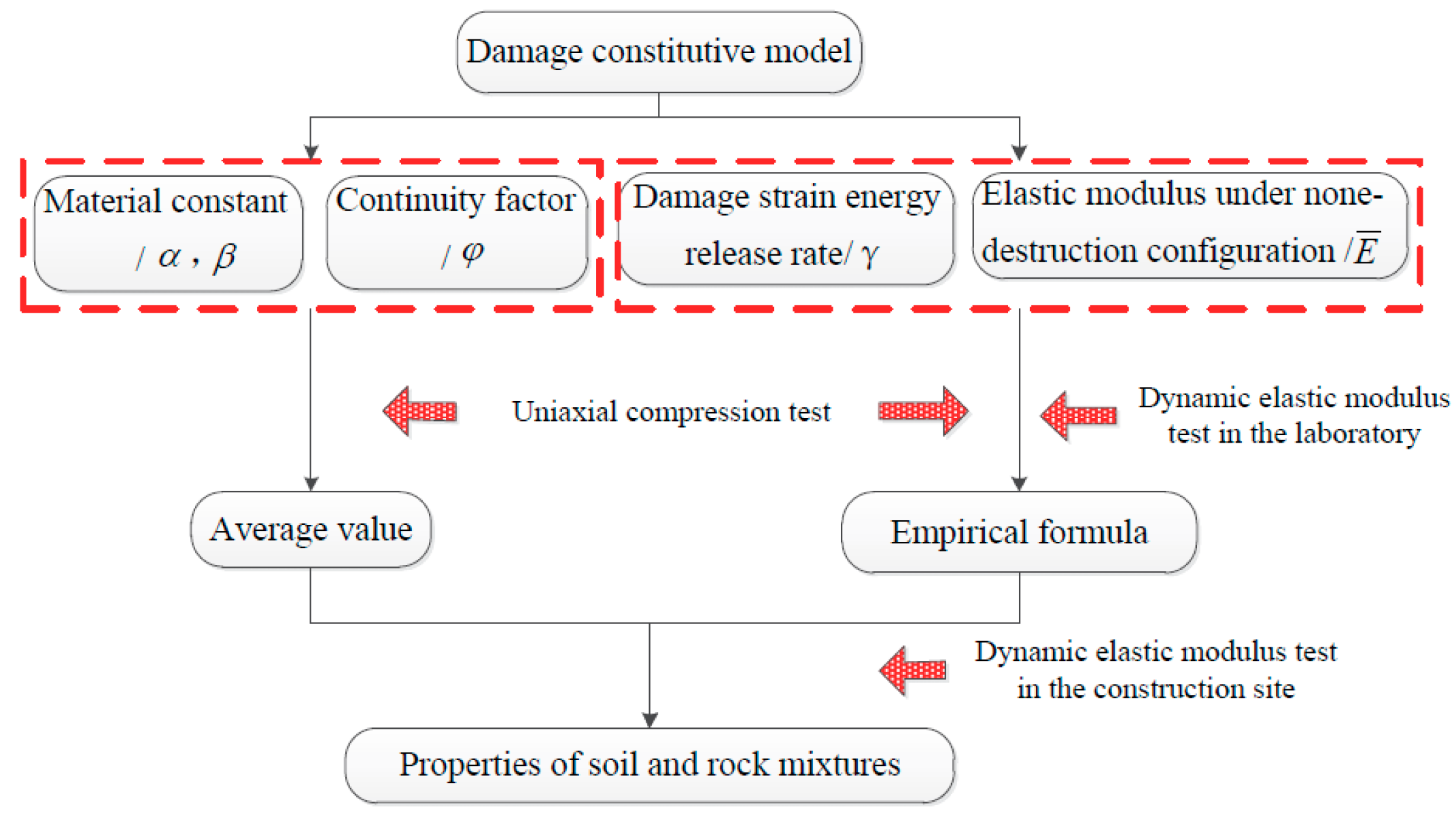
5. Damage Constitutive Model

As mentioned above, strain softening and ductile deformation are the dominant mechanical behaviors in the post-failure region. The deformation characteristics in the post peak zone are of great significance, especially in the construction and design process of mine pillars [30]. Previous studies indicated that damage mechanics is an effective way to study the fracture initiation and evolution process [31,32]. Thus, in this paper, a damage constitutive model was proposed to study the mechanical behavior of the bimrocks with high RBPs.
The uniaxial compression process can be considered a series of quasi-static processes [32], in which the initial and final states of the elastic energy are 0. Therefore, the mechanical energy absorbed by the specimen (from the intact to failure) was used for damage evolution. The mechanical energy consumed per unit volume during the entire process of uniaxial compression was defined as the damage strain energy release rate [33,34,35]. Based on this concept, the ratio between mechanical energy consumption and the damage strain energy release rate per unit volume was defined as the damage done to the bimrocks. For any state of damage, it was assumed that the relation between the nominal stress and effective stress was as follows:
σ = ( 1 D ) α σ ¯ ,
where σ is the nominal stress, σ ¯ is the effective stress, and α is the material constant.
In the process of uniaxial compression, the deformation of the specimen is composed of two parts, elastic strain and strain caused by damage [36,37], as follows:
ε = ( ε e + ε d ) ,
where ε , ε e , and ε d are the total strain, elastic strain, and damage strain of the damaged material.
As the strain caused by damage does not contribute to the nominal stress, the constitutive equation of the welded bimrocks in any damage state should be as follows [38,39]:
σ = E ( ε ε d ) ,
where E is the elastic modulus of the damaged material.
Based on the experimental results, the process of elastic modulus deterioration and damage evolution was shown to have clear nonlinear characteristics. Thus, the energy equivalence hypothesis was adopted to describe the nonlinear mechanical behavior during the loading process, which assumes that the strain energy caused by nominal stress is equal to that induced by effective stress [40,41]:
W = 1 2 E ε e 2 = 1 2 σ 2 E = 1 2 σ ¯ 2 E ¯ = 1 2 E ¯ ε ¯ e 2 = W ¯ ,
where E ¯ and ε ¯ e are the elastic modulus and elastic strain of the intact material, respectively.
By combining Equation (4) and Equation (7), we can obtain the following equation:
E = ( 1 D ) 2 α E ¯ = φ 2 α E ¯ ,
where φ is defined as the continuity factor.
With an increase in the damage, the irreversible damage strain grows accordingly. To determine the quantitative relation between the damage and irreversible deformation, it was assumed that the elastic strain and total strain satisfy the following:
ε e = ε ε d = ( 1 D ) β ε = φ β ε ,
where β is a material constant.
Further, using Equation (6), Equation (8), and Equation (9) simultaneously, the following equation can be obtained:
σ = ( 1 D ) 2 α + β E ¯ ε = φ 2 α + β E ¯ ε .
Equation (10) is the damage constitutive equation of welded bimrocks. To obtain the damage evolution equation, it is necessary to establish the internal relation between the total strain and damage. Considering an arbitrary element of the bimrocks, the relation can be obtained according to the law of energy conservation [37,38,39], as follows:
d w = d w e + d w D ,
where d w is the total energy absorbed from the external loading per unit volume, d w e is the elastic energy stored by the unit volume, and d w D is the mechanical energy consumed per unit volume due to damage.
According to the definition of damage, the mechanical energy consumed due to damage can be defined as follows:
d w D = γ · d D = γ · d φ ,
where γ is the release rate of the damage strain energy.
The calculation formulas of d w and d w e are as follows:
d w = σ d ε = 1 2 E ¯ φ 2 α + β d ε 2 ,
d w e = σ d ε e = β E ¯ φ 2 α + 2 β - 1 ε 2 d φ + 1 2 E ¯ φ 2 α + 2 β d ε 2 .
Using Equations (11)–(14), simultaneously, the following can be obtained:
1 2 E ¯ φ 2 α + β d ε 2 = β E ¯ φ 2 α + 2 β - 1 ε 2 d φ + 1 2 E ¯ φ 2 α + 2 β d ε 2 - γ d φ .
The initial conditions are
φ = φ 0 , ε 2 = 0 ,
where φ 0 is the initial continuity factor of the material.
Combined with Equation (16), the solution of Equation (15) can be obtained as follows:
ε 2 γ / E ¯ = 2 ( 1 φ β ) 2 [ 1 1 2 α ( φ 1 2 α - φ 0 1 2 α ) + 1 1 2 α β ( φ 0 1 2 α β φ 1 2 α β ) ] .
The symbols and B are defined as the dimensionless stress and strain and the corresponding expressions are as follows:
= σ γ E ¯ , B = ε γ / E ¯ .
Then, Equation (10) can be rewritten as follows:
= ϕ 2 α + β B .
As can be seen, the values of dimensionless stress and strain are determined by α , β , and φ 0 . Given α , β , and φ 0 , the form of the constitutive curve is determined. The actual stress and strain can be obtained according to the internal relation between the variables described in Equation (18). The constitutive parameters of γ and E ¯ can be calibrated using the following formulas:
γ = σ max ε max max B max , E ¯ = σ max B max max ε max ,
where σ max and ε max are the peak stress and strain of the test results and the values max and B max are the dimensionless peak stress and strain.
Based on the damage constitutive model mentioned above, the particle swarm optimization (PSO) algorithm was adopted to fit the results of the uniaxial compression test. The fitting results are illustrated in Figure 10 and Table 2. The value E t e s t in Table 2 was obtained from the slope of the linear part in the pre-peak region of the curves in Figure 10. It was observed that a non-linear concave upward section exists before the linear part of the curves, which is caused by the closure of voids and pre-existing fissures in the specimen [13]. Thus, the predicted elastic modulus was relatively lower than the E t e s t , with a maximum error of 16.5%. However, a conservative approach is usually adopted during the construction and design stage of underground engineering for the sake of safety. Consequently, a reasonably reduced prediction of the elastic modulus that benefits the reliability of the underground engineering is acceptable. The R2 value in Table 2 was obtained based on the data of both predicted and experimental results in the post peak zone. As can be seen, the minimum value of R2 was 0.85. This indicates that the proposed model offers an effective description for the strain softening and ductile behavior of bimrocks, especially when the RBP is larger than 70%.
As shown in Table 2, α and β are the material constants of welded bimrocks, which increase with the improvement of the rock proportion. This implies that the nominal stress and elastic strain of the welded bimrocks with high rock contents are more sensitive to damage. The value φ 0 represents the initial continuity of the bimrocks. A higher RBP corresponds to a lower initial continuity based on the data in Table 2. However, the divergences of the α , β , and φ 0 of bimrocks with different RBPs are relatively insignificant, which has a limited influence on the mechanical behavior.
In contrast, the release rate of the damage strain energy γ and the elastic modulus of the intact state E ¯ was shown to decrease rapidly with an increase in RBP, which indicates a significant difference. Thus, these parameters can be used as a characteristic index to distinguish among welded bimrocks with different RBPs.

6. Fast Discrimination Method of Bimrocks Physical Properties

In remote areas and inconvenient construction sites, it is often impossible to utilize a full range of experimental equipment to test the mechanical properties of bimrocks. The resonance frequency tester has the advantages of portability and easy operation. The dynamic elastic modulus of core samples at the site can be easily obtained from the resonance frequency test results. By establishing correlations between the dynamic elastic modulus and physical parameters, which include the mechanical parameters and damage constitutive parameters, this method offers a new way to quickly discriminate the physical characteristics of bimrocks at an engineering site.

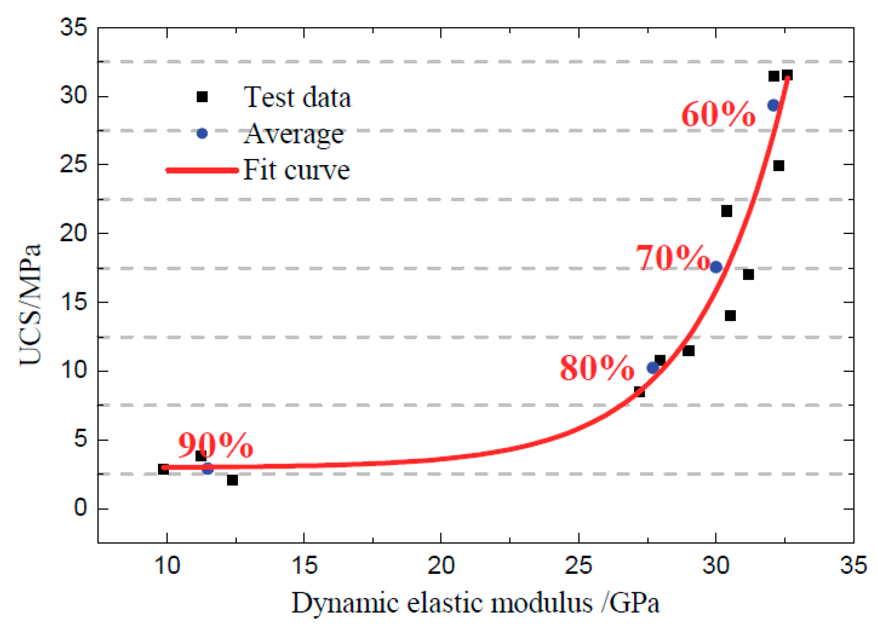
6.1. Relationship between the Dynamic Elastic Modulus and Mechanical Parameters

Figure 11 illustrates the relationships between the dynamic elastic modulus and UCS. The UCS increased exponentially with an increase in the dynamic elastic modulus. This can be expressed as follows:
U C S = 1.48 · 10 3 · exp ( E d / 3.3 ) + 2.97 ;   R 2 = 0.93 ,
where E d is the dynamic elastic modulus.
Two additional main conclusions can be drawn based on the data shown in Figure 11.
(1)
In the process of reducing the RBP from 90% to 80%, the matrix filled most of the gaps between rocks. In the interim, the compactness of the specimens increased, which led to a corresponding rapid increase in the dynamic elastic modulus. However, the strength of the welded bimrocks was still mainly dependent on the bond strength of the soil rock interface in this case. Thus, the UCS did not increase significantly.
(2)
With a further reduction in the RBP, the compaction degree of the specimens continued to increase. Meanwhile, the dynamic elastic modulus grew steadily. As shown in Figure 11, the UCS underwent a relatively significant change, even though the dynamic elastic modulus varied slightly. Thus, we infer that the dominant influencing factor of the UCS gradually changed from the interface strength to the matrix ratio and strength in this period.

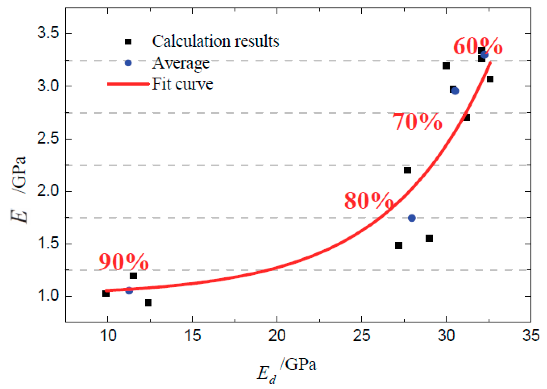
6.2. Relationship between the Dynamic Elastic Modulus and Calibration Parameters

The relation between the dynamic elastic modulus and calibration parameters in the damage constitutive model was further explored. The specific data and fitting curves are shown in Figure 12 and Figure 13.
As shown in Figure 12 and Figure 13, with a decrease in the RBP, the overall compactness and stiffness of the specimens increased gradually, which resulted in improvements in the dynamic elastic modulus, the release rate of the damage strain energy, and the elastic modulus of the intact state. The fitting results show that the relations between the dynamic elastic modulus and damage constitutive parameters (i.e., the damage strain energy release rate and elastic modulus of the intact state) can be well described by the exponential function. The specific fitting formulas are as follows:
γ = 1.83 · 10 3 · exp ( E d / 2.77 ) + 28.28 ;   R 2 = 0.87 ,
E ¯ = 9.22 10 3 · exp ( E d / 5.94 ) + 1.01 ;   R 2 = 0.81 .
In combination with Section 6.1 and Section 6.2, the dynamic elastic modulus of the welded bimrocks showed corresponding relations with the physical parameters (including mechanical parameters and damage calibration parameters). By means of a uniaxial compression test and a vibration signal test of standard specimens, the empirical formulas between the dynamic elastic modulus and mechanical parameters as well as the dynamic elastic modulus and damage calibration parameters can be calibrated. As the discrepancy of the α , β , and φ of bimrocks with different RBPs is relatively limited, it is acceptable to set them as constants according to the means of the calibration results. On this basis, the strength of the welded bimrocks can be quickly judged by the dynamic elastic modulus of the core sample. Furthermore, the strain softening and ductile behavior of the welded bimrocks can be obtained based on the damage constitutive model established above, which offers the basic and crucial references for the design and construction of underground engineering [30]. The proposed technical process is illustrated in Figure 14.

7. Conclusions

Bimrocks with high RBPs represent a kind of complicated and problematic geological mixture due to their high heterogeneity and porosity, thereby requiring extraordinary efforts to determine their mechanical properties, especially in mining projects [42,43]. The complete stress strain curve of a uniaxial compression test offers a fundamental reference for a successful underground engineering design [44]. However, it is laborious, costly, and even impossible to conduct the laboratory test at the construction site due to budget limitations and inconvenient traffic. Although some studies have introduced non-destruction test technologies to obtain the mechanical properties of the bimrocks, as mentioned in the introduction [19,20,21,22,23,24], none of them studied the internal connection between resonance test technology and the mechanical behavior of the bimrocks.
In this paper, based on the resonance test technology, the vibration attenuation signals and dynamic elastic modulus of the bimrocks with high rock contents were obtained. A uniaxial compression test was conducted to study the bimrocks’ mechanical deformation characteristics. Based on the damage theory, a constitutive model was proposed to describe the mechanical behavior of the welded bimrocks, especially the post-peak mechanical characteristics. On this basis, the relations between the dynamic elastic modulus and the physical parameters of the bimrocks were established. Subsequently, a new method was proposed to provide fast identification of the mechanical properties of bimrocks.
The results of the resonant frequency test showed that the specimens with higher RBPs had lower resonant frequencies. A clear exponential trend was observed between the RBP and the dynamic elastic modulus, which is a mechanical parameter derived from the resonant frequency [29]. Combined with the results of the uniaxial compression test, significant correlations were found between the dynamic elastic modulus and the UCS. This indicates that the dynamic elastic modulus is an effective parameter for predicting the mechanical properties of bimrocks with high RBPs in a rapid and convenient manner. As the resonant frequency tester is portable and easy to operate, it can be used to monitor the strength of the surrounding rock mass at sites during the construction process so that the stability and safety of a mining or tunneling project can be further guaranteed.
Based on the damage theory, a constitutive model of welded bimrocks was proposed to study the strain softening and ductile behavior of the bimrocks. Compared with the experimental results, the elastic modulus obtained from the constitutive model were relatively small due to the porous structure and pre-existing fissures of the specimens. However, a conservative approach is usually adapted during the design stage of underground engineering. Thus, a reasonable reduction in prediction results is acceptable considering the uncertainty and randomness of geological masses. According to the fitting results, the proposed constitutive model can accurately simulate the strain softening and ductile behavior in the post peak zone, which provides crucial information to avoid potential hazards induced by the insufficient stability control of surrounding rocks [13,44].
Significant correlations were found between the dynamic elastic modulus and two crucial parameters of the constitutive model using the empirical approach. Thus, by combining the resonant frequency technology with the proposed constitutive model, a technical process was proposed to obtain the complete stress strain curve, which could be useful for understanding the total process of deformation, cracking, and eventual destruction of bimrocks and could provide insight into potential rock mass behavior at construction sites [45].

Author Contributions

Methodology, Y.L.; Writing—original draft preparation, Y.L.; Writing—review and editing, M.L. and X.W.; Supervision, L.P., C.S. and C.C.; project administration, L.P. and M.L.; funding acquisition, L.P. and M.L.

Funding

This research was funded by the National Natural Science Foundation of China (no. 51978669, U1734208), are gratefully acknowledged.

Conflicts of Interest

The authors declare no conflict of interest.

References

  1. Xu, W.; Hu, R.; Tan, R.; Zeng, R.; Yu, H. Study on field test of rock-soil aggregate on right bank of Longpan in tiger-leaping gorge area. Chin. J. Rock Mech. Eng. 2006, 25, 1270–1277. [Google Scholar]
  2. Xu, W.J.; Hu, R.L. Some geomechanical properties of soil–rock mixtures in the Hutiao Gorge area, China. Geotech 2007, 3, 255–264. [Google Scholar] [CrossRef]
  3. Li, X.; Liao, Q.L.; He, J.M.; Chen, J. Study on in-situ tests of mechanical characteristics on soil-rock aggregate. Chin. J. Rock Mech. Eng. 2007, 26, 2377–2384. [Google Scholar]
  4. Xu, W.J.; Wang, S. Meso-mechanics of soil-rock mixture with real shape of rock blocks based on 3D. Chin. J. Rock Mech. Eng. 2016, 35, 2152–2160. (In Chinese) [Google Scholar]
  5. Coli, N.; Berry, P.; Boldini, D. In situ non-conventional shear tests for the mechanical characterisation of a bimrock. Int. J. Rock Mech. Min. Sci. 2011, 48, 95–102. [Google Scholar] [CrossRef]
  6. Yue, Z.Q.; Chen, S.; Tham, L.G. Finite element modeling of geomaterials using digital image processing. Comput. Geotech. 2003, 30, 375–397. [Google Scholar] [CrossRef]
  7. Xu, W.J.; Yue, Z.Q.; Hu, R.L. Study on the mesostructure and mesomechanical characteristics of the soil–rock mixture using digital image processing based finite element method. Int. J. Rock Mech. Min. Sci. 2008, 45, 749–762. [Google Scholar] [CrossRef]
  8. Ding, X.; Li, Y.; Wang, X. Particle flow modeling mechanical properties of soil and rock mixtures based on digital image. Chin. J. Rock Mech. Eng. 2010, 29, 477–484. (In Chinese) [Google Scholar]
  9. Yue, Z. Digital representation of mesogeomaterial spatial distribution and associated numerical analysis of geomechanics: Methods, applications and development. Chin. J. Rock Mech. Eng. 2006, 25, 875–888. (In Chinese) [Google Scholar]
  10. Qiu, P.; Hu, R.; Hu, L.; Liu, Q.; Xing, Y.; Yang, H.; Qi, J.; Ptak, T. A Numerical Study on Travel Time Based Hydraulic Tomography Using the SIRT Algorithm with Cimmino Iteration. Water 2019, 11, 909. [Google Scholar] [CrossRef]
  11. Taherdangkoo, R.; Taherdangkoo, M. Modified stem cells algorithm-based neural network applied to bottom hole circulating pressure in underbalanced drilling. Int. J. Pet. Eng. 2015, 1, 178–188. [Google Scholar] [CrossRef]
  12. Afifipour, M.; Moarefvand, P. Mechanical behavior of bimrocks having high rock block proportion. Int. J. Rock Mech. Min. Sci. 2014, 65, 40–48. [Google Scholar] [CrossRef]
  13. Afifipour, M.; Moarefvand, P. Experimental study of post-peak behavior of bimrocks with high rock block proportions. J. Central South Univ. 2014, 21, 761–767. [Google Scholar] [CrossRef]
  14. Sonmez, H.; Ercanoglu, M.; Kalender, A.; Dagdelenler, G.; Tunusluoglu, C. Predicting uniaxial compressive strength and deformation modulus of volcanic bimrock considering engineering dimension. Int. J. Rock Mech. Min. Sci. 2016, 86, 91–103. [Google Scholar] [CrossRef]
  15. Kalender, A.; Sonmez, H.; Medley, E.; Tunusluoglu, C.; Kasapoglu, K.E. An approach to predicting the overall strengths of unwelded bimrocks and bimsoils. Eng. Geol. 2014, 183, 65–79. [Google Scholar] [CrossRef]
  16. Lindquist, E.S. The Strength and Deformation Properties of Melange. Ph.D. Thesis, Department of Civil Engineering, University of California, Berkeley, CA, USA, 1994. [Google Scholar]
  17. Altinsoy, H. A Physical Based Model Investigation for Determination of Shear Strength of Block in Matrix Rocks. Master’s Thesis, Geological Engineering Department, Hacettepe University, Ankara, Turkey, 2006. [Google Scholar]
  18. Coskun, A. Development of an Empirical Approach to Overcome the Problems foBoundary Condition between Bimrocks and Jointed Rock Masses. Master’s Thesis, Geological Engineering Department, Hacettepe University, Ankara, Turkey, 2010. [Google Scholar]
  19. Mahdevari, S.; Maarefvand, P. Applying ultrasonic waves to evaluate the volumetric block proportion of bimrocks. Arab. J. Geosci. 2017, 10, 204. [Google Scholar] [CrossRef]
  20. Slatalla, N.; Alber, M.; Kahraman, S. Analyses of acoustic emission response of a fault breccia in uniaxial deformation. Bull. Eng. Geol. Environ. 2010, 69, 455–463. [Google Scholar] [CrossRef]
  21. Wang, Y.; Li, X. Experimental study on cracking damage characteristics of a soil and rock mixture by UPV testing. Bull. Eng. Geol. Environ. 2015, 74, 775–788. [Google Scholar] [CrossRef]
  22. Wang, Y.; Li, X.; Hu, R.L.; Li, S.D.; Wang, J.Y. Experimental study of the ultrasonic and mechanical properties of SRM under compressive loading. Environ. Earth Sci. 2015, 74, 5023–5037. [Google Scholar] [CrossRef]
  23. Sun, H.F.; Xing, M.X.; Yang, Y.M.; Ju, Y. Damage characterization and analysis of SRM during uniaxial compression. In Proceedings of the 3rd International-Society-for-Rock-Mechanics (ISRM) SINOROCK Symposium, Shanghai, China, 18–20 June 2013; pp. 219–224. [Google Scholar]
  24. Wang, Y.; Li, C.H.; Hu, Y.Z. Use of X-ray computed tomography to investigate the effect of rock blocks on meso-structural changes in soil-rock mixture under triaxial deformation. Constr. Build. Mater. 2018, 164, 386–399. [Google Scholar] [CrossRef]
  25. Medley, E.W. The Engineering Characterization of meLanges and Similar Block-in-Matrix Rocks (bimrocks). Ph.D. Thesis, University of California, Berkeley, CA, USA, 1994. [Google Scholar]
  26. Medley, E. Orderly Characterization of Chaotic Franciscan melanges. Eng. Geol. 2001, 4, 20–32. [Google Scholar]
  27. Nanjiing Water Conservancy Science Research Institute. Soil Test Technical Manuals; China Communication Press: Beijing, China, 2004; pp. 17–73. (In Chinese) [Google Scholar]
  28. British Standard. Methods of Test for Soils for Civil Engineering Purposes—Part 1: General Requirements and Sample Preparation, BS1377-1; British Standard Institution: London, UK, 1990. [Google Scholar]
  29. Operator’s Manual for E-Meter MK Ⅱ Resonance Frequency Tester; James Instruments incorporated company: Chicago, IL, USA, 2013; pp. 24–25.
  30. Bieniawski, Z.T. Rock Mechanics Design in Mining and Tunneling; A.A. Balkema Publications: Rotterdam, The Netherlands, 1984; p. 271. [Google Scholar]
  31. Chaboche, J.L. Continuum damage mechanics—A tool to describe phenomena before crack initiation. Nucl. Eng. Des. 1981, 64, 233–247. [Google Scholar] [CrossRef]
  32. Lemaitre, J.; Chaboche, J.L. Mechanics of Solid Materials; Cambridge University Press: Cambridge, UK, 1990. [Google Scholar]
  33. Dougill, J.W. On stable progressively fraxturing solid. J. Appl. Math. Phys. 1967, 27, 432–437. [Google Scholar]
  34. Lemaitre, J. How to use damage mechanics. Nucl. Eng. Des. 1984, 80, 233–245. [Google Scholar] [CrossRef]
  35. Richard, B.; Ragueneau, F.; Cremona, C.; Adelaide, L. Isotropic continuum damage mechanics for concrete under cyclic loading: Stiffness recovery, inelastic strains and frictional sliding. Eng. Fract. Mech. 2010, 77, 1203–1223. [Google Scholar] [CrossRef]
  36. Liu, N.; Peng, L.; Shi, C.; Lei, M. Experimental and model study on dynamic behaviour and fatigue damage of tunnel invert. Constr. Build. Mater. 2016, 126, 777–784. [Google Scholar] [CrossRef]
  37. Ma, J.; Zhao, G.; Khalili, N. A fully coupled flow deformation model for elasto-plastic damage analysis in saturated fractured porous media. Int. J. Plast. 2016, 76, 29–50. [Google Scholar] [CrossRef]
  38. Ma, J.; Zhao, G.; Khalili, N. An elastoplastic damage model for fractured porous media. Mech. Mater. 2016, 100, 41–54. [Google Scholar] [CrossRef] [Green Version]
  39. Ma, J.; Wang, J. A Stress-Induced Permeability Evolution Model for Fissured Porous Media. Rock Mech. Rock Eng. 2016, 49, 477–485. [Google Scholar] [CrossRef]
  40. Reckwerth, D.; Tsakmakis, C. The principle of generalized energy equivalence in continuum damage mechancis. In Deformation and Failure in Metallic Materials; Springer: Berlin/Heidelberg, Germany, 2003; pp. 381–406. [Google Scholar]
  41. Voyiadjis, G.Z.; Kattan, P.I. A generalized hypothesis of elastic energy equivalence in continuum damage mechanics. Eng. Trans. 2017, 65, 351–369. [Google Scholar]
  42. Hustrulid, W.A.; Bullock, R.L. Underground Mining Methods: Engineering Fundamentals and International Case Studies; Society for Mining, Metallurgy, and Exploration, Inc. (SME): Littleton, CO, USA, 2001. [Google Scholar]
  43. Benzaazoua, M.; Fall, M.; Belen, T. A contribution to understanding the hardening process of cemented pastefill. Miner. Eng. 2004, 17, 141–152. [Google Scholar] [CrossRef]
  44. Afifipour, M.; Moarefvand, P. Failure patterns of geomaterials with block-in-matrix texture: Experimental and numerical evaluation. Arab. J. Geosci. 2014, 7, 2781–2792. [Google Scholar] [CrossRef]
  45. Fairhurst, C.E.; Hudson, J.A. Draft ISRM suggested method for the complete stress-strain curve for intact rock in uniaxial compression. Int. J. Rock Mech. Mining Sci. 1999, 36, 279–289. [Google Scholar]
Figure 1. Samples of the bimrocks with high rock block proportions. (a) Ice-water accumulated bimrocks. (b) Bimrocks of misis fault breccia. (c) Bimrocks of gravel deposit. (d) Volcanic bimrocks.
Applsci 09 03537 g001
Figure 2. Block gradation curve.
Applsci 09 03537 g002
Figure 3. Samples with different rock block proportions.
Applsci 09 03537 g003
Figure 4. Universal testing machine and resonance frequency tester.
Applsci 09 03537 g004
Figure 5. Time frequency analysis of the vibration signal.
Applsci 09 03537 g005
Figure 6. Relation curve of the dynamic elastic modulus and RBP.
Applsci 09 03537 g006
Figure 7. Typical stress-strain curves for cylindrical specimens of welded bimrocks.
Applsci 09 03537 g007
Figure 8. Distribution curve of UCS of specimens with different RBPs.
Applsci 09 03537 g008
Figure 9. Failure modes of specimens with different rock contents.
Applsci 09 03537 g009
Figure 10. Fitting results.
Applsci 09 03537 g010
Figure 11. Relationship between the dynamic elastic modulus and UCS.
Applsci 09 03537 g011
Figure 12. Relationship between the dynamic elastic modulus and the damage strain energy release rate.
Applsci 09 03537 g012
Figure 13. The relationship between the dynamic elastic modulus and elastic modulus in the intact state.
Applsci 09 03537 g013
Figure 14. Technical process.
Applsci 09 03537 g014
Table 1. The UCS values for the bimrocks with the various RBP.
RBPSpecimen-1Specimen-2Specimen-3Average
60%31.4931.5824.9729.35
70%21.6517.0414.0117.57
80%8.4911.4610.7410.23
90%2.822.043.822.89
Table 2. Calibration results of constitutive parameters.
RBP φ 0 γ /kPa E ¯ /GPa β α R2 (post peak zone) E t e s t / GPa
60%0.97215.763.240.260.540.903.88
70%0.95118.812.920.280.570.853.19
80%0.9146.981.530.300.580.941.68
90%0.8515.420.790.330.600.970.93

