Article

A Novel Method for the Measurement of Geometric Errors in the Linear Motion of CNC Machine Tools

1
State Key Laboratory of Precision Measuring Technology and Instruments, Tianjin University, Tianjin 300072, China
2
Key Laboratory of Advanced Transducers and Intelligent Control System, Ministry of Education, Taiyuan University of Technology, Taiyuan 030024, China
3
Centre of Micro/Nano Manufacturing Technology (MNMT-Dublin), University College Dublin, Dublin 999015, Ireland
*
Authors to whom correspondence should be addressed.
These authors contributed equally to this work.
Appl. Sci. 2019, 9(16), 3357; https://doi.org/10.3390/app9163357
Submission received: 31 July 2019 / Revised: 9 August 2019 / Accepted: 12 August 2019 / Published: 15 August 2019
(This article belongs to the Section Optics and Lasers)

Abstract

:
In order to improve the accuracy of the linear motion of computer numerical control (CNC) machine tools, a novel method based on a new type of 1-D (1-dimensional) artifact is proposed to measure the geometric errors. Based on the properties of the displacement measurement of a revolutionary paraboloid and the angle measurement of plane mirrors, the 1-D artifact can be applied to identify position errors and angle errors. Meanwhile, the concrete 6 degrees-of-freedom error identification method is described in this paper in sufficient detail. Through measuring the 1-D artifact horizontally and vertically using the machine tool, the geometric errors can be obtained by calculating the deviation between the characteristic parameter of the 1-D artifact measured by the machine tool and that measured by a more precise method, for example, laser interferometry. Experiments were carried out on a coordinate measuring machine, and the validity and accuracy of the method were discussed by comparing the result with the identification error measured by a laser interferometer.

1. Introduction

With the rapid development of mechanical manufacturing, CNC (computer numerical control) machine tools cover a wide range of applications in the mold manufacturing industry, electronic engineering, and the automotive and aerospace industries [1,2]. Owing to its advantages of being all-purpose with high precision and a large processing scope, it has become a very necessary type of equipment [3]. As is widely known, precision plays a key role in CNC machine tools, and this is a hot topic in the machining automation domain.
Generally speaking, there are two approaches to enhance accuracy. One is error avoidance, i.e., improving processing techniques, which is effective but costs plenty of resources. The other is error compensation, which is conducted by obtaining the original errors of CNC machine tools by some measuring method [4]. Clearly, as an economical and efficient method, error compensation has attracted the attention of many researchers. The guide rail of machine tools has 6 degrees-of-freedom errors in linear motion [5]. As the most accurate method, laser interferometers are widely applied to identification of the geometric error of the linear guideway [6,7]. However, laser interferometers have a high price and tedious operation as the cost of their high precision.
The R-test, invented by Weikert et al. [8], was further used to measure the location errors of a guide way by Ibaraki et al. [9]. Yamaji Masashi improved the R-test device to incorporate three displacement sensors designed to simultaneously collect far more information [10]. Another method is to calibrate the errors with standard parts, such as a ball-bar and a ball-plate. For example, Cheng Fang realized the determination of the geometric error parameters of CMMs (coordinate measuring machines) using a 1-D artifact (i.e., a 1-D ball-bar) [11]. Tsutsumi proposed a classical measuring method, i.e., to conduct ball bar tests in axial, radial, and tangential directions and identify PIGEs (position-independent geometric errors) by analyzing the eccentricities of the circular trajectory [12]; this method has been accepted by many scholars and is included in ISO 10791-6 [13].
In this article, we propose a systematic method to identify geometric errors in the linear motion of CNC machine tools based on an innovative 1-D artifact. The 1-D artifact is composed of a series of surface mirror targets. Furthermore, each target includes a revolutionary paraboloid and a plane mirror. The former is designed to measure the 2-D displacement and identify the 2-D original location error of machine tools, and the latter is to identify the 2-D original angle error. We can obtain 4 degrees-of-freedom errors by measuring the 1-D artifact using an angle sensor driven by a machine tool in one direction. Then, by rotating the 1-D artifact 90 ° , the other 2 degrees-of-freedom errors can be obtained by another measurement. As such, the method can realize the measurement of the geometric errors in the linear motion of machine tools; the result was compared with that obtained by laser interferometer.

2. Measurement Mechanism

2.1. Geometric Errors of a Linear Motion Guide Rail

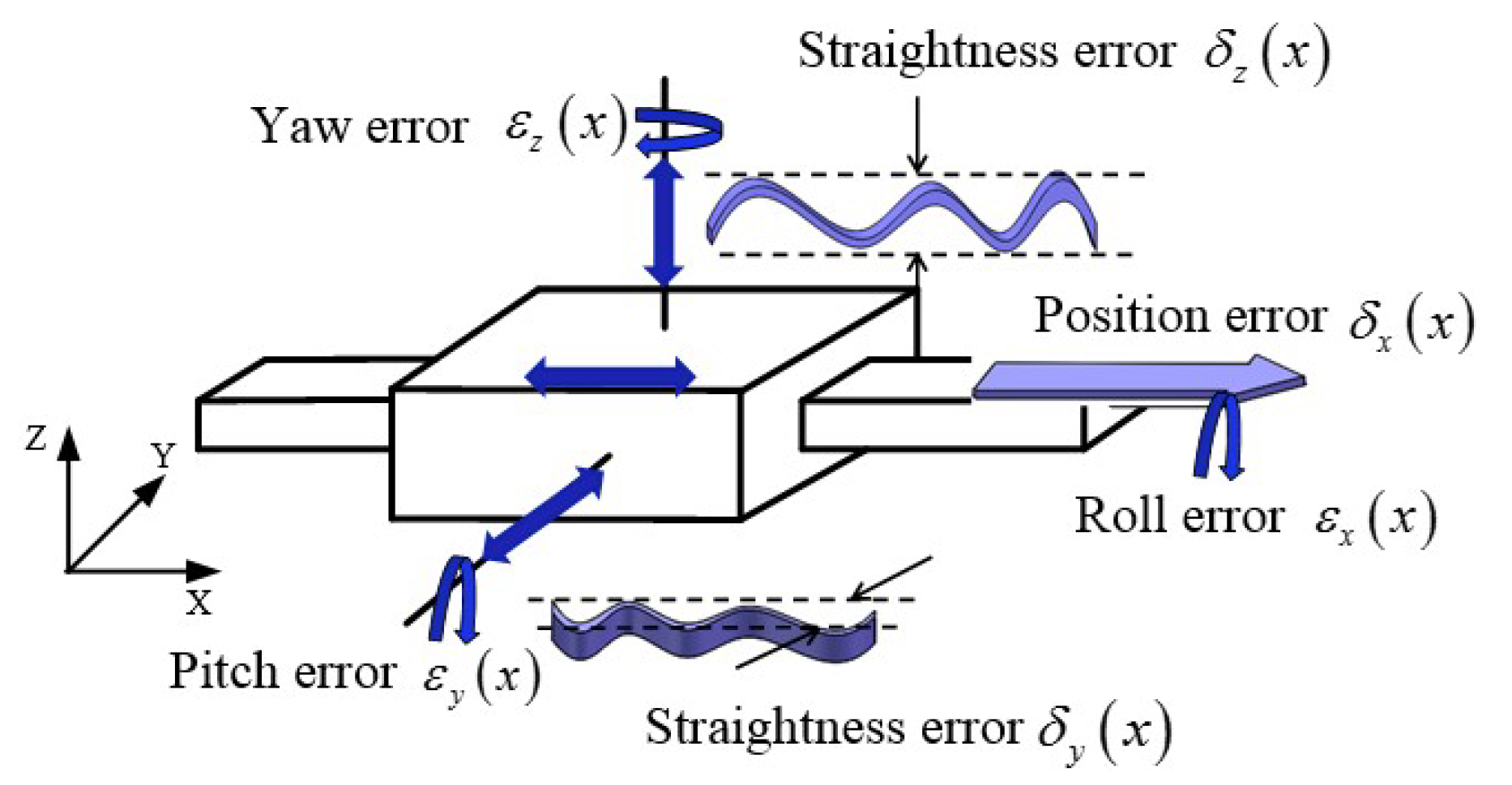
Any object without constraints has 6 degrees of freedom, which means it can move along or rotate around any direction. Due to imperfect manufacture, the guide rail may have micro-movements in every direction; as such, each axis has 6 degrees-of-freedom errors [14]. Take the X-axis, for example: Figure 1 shows the 6 degrees-of-freedom errors, namely, position error δ x ( x ) , the horizontal straightness error δ y ( x ) , the vertical straightness error δ z ( x ) , the roll error ε x ( x ) , the yaw error ε z ( x ) , and the pitch error ε y ( x ) .

2.2. Design of the 1-D Artifact

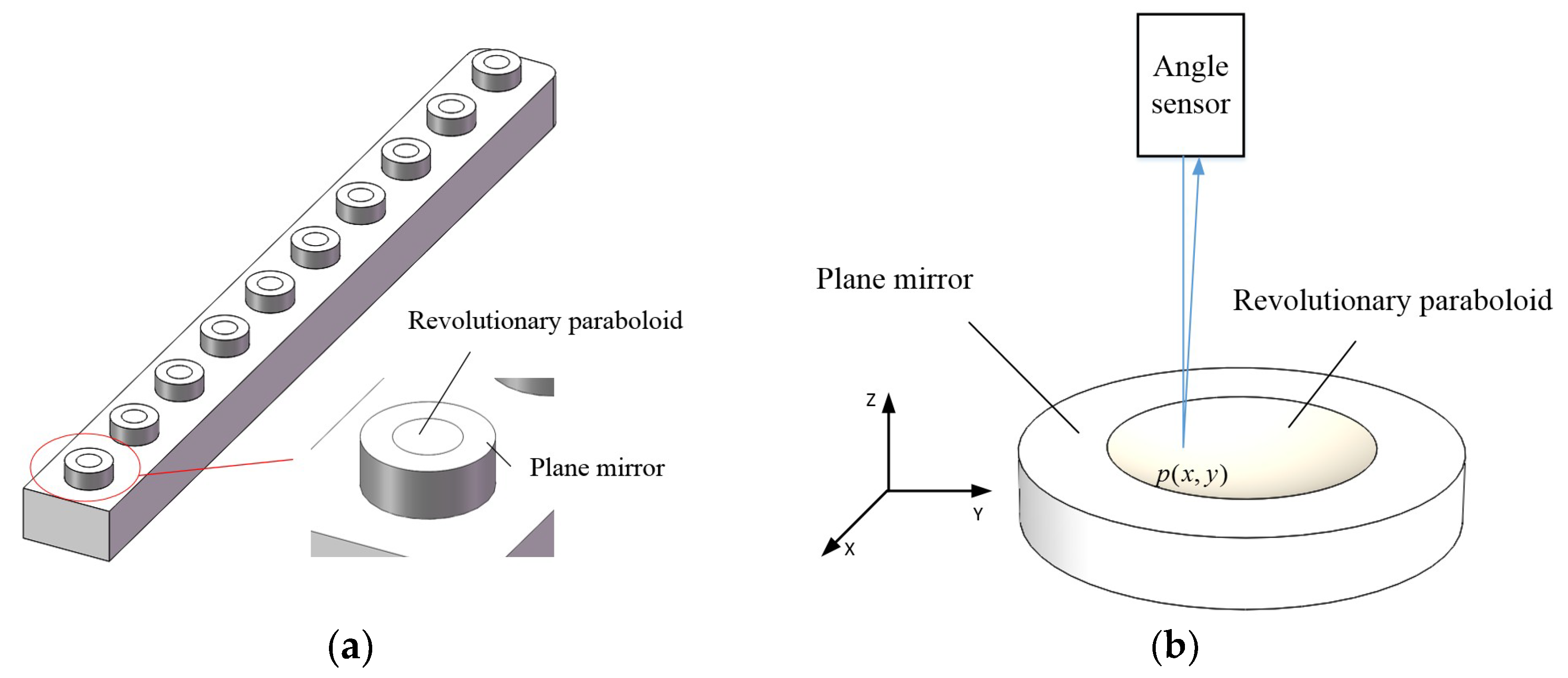
To identify the geometric errors of machine tools, a novel 1-D artifact was designed with measurement targets fixed on it as Figure 2a illustrates. As Figure 2b shows, the target is composed of a plane mirror with a diameter of 10 mm and a revolutionary paraboloid with a diameter of 5 mm. The equation of the revolutionary paraboloid satisfies:
x 2 0.1547 + y 2 0.1547 = 2 z   ( unit :   m ) .
The distance of the two targets is approximately 50 mm, and nine targets were selected for a measured linear range of 400 mm. The angle sensor can obtain 2-D angle information by measuring the plane mirror and obtain 2-D micro displacement information by measuring the revolutionary paraboloid.
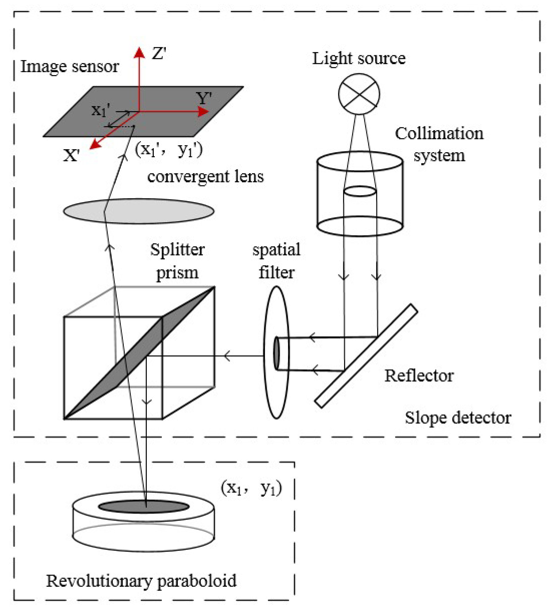
Zekui Lv elaborated the mechanism by which an angle sensor identifies 2-D micro displacement information by measuring a revolutionary paraboloid in his paper [15]. Figure 3 illustrates the principle of measuring the optical path. Based on the principle of optical auto-collimation, the spot displacement is linearly related to the angle of the measuring surface in the small angle range [16]. On the other hand, the displacement of the reflection point on the revolutionary paraboloid is also linearly related with the tangent plane angle at the reflection point. Thus, the spot displacement is proportional to the displacement of the reflection point.

2.3. Identification of Geometric Errors

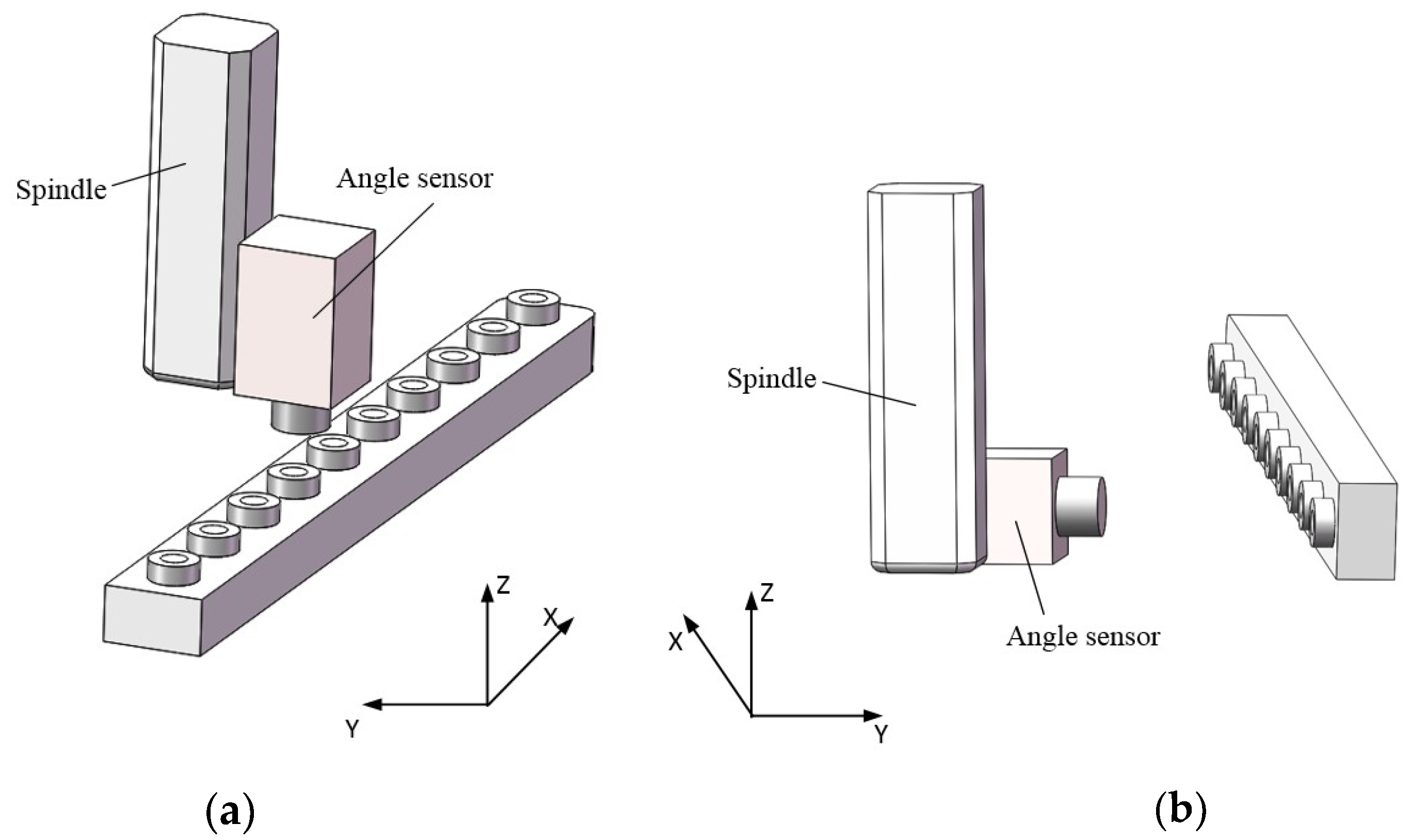
We took the X-axis geometric error measurement as an example; measurement for the Y-axis and Z-axis was similar. As Figure 4a shows, the spindle of the machine tool drives the angle sensor in the X direction with the 1-D artifact laid on the X-axis horizontally. The roll error ε x ( x ) , the pitch error ε y ( x ) , the position error δ x ( x ) , and the horizontal straightness error δ y ( x ) can be identified by measurement of the plane mirrors and revolutionary paraboloids. In the case of good repeatability of the machine tools, the geometric errors remain approximately constant along the same motion path. Therefore, when the 1-D artifact is laid on the X-axis vertically, as shown in the Figure 4b, the yaw error ε z ( x ) and the vertical straightness error δ z ( x ) can be identified.
Actually, due to the different orientation and position of each target, what the angle sensor obtains is the relative 2-D angle and 2-D position information of targets. Before identifying the geometric errors of the machine tools, the relative angle and position information should be calibrated by a laser interferometer or by machine tools with higher precision. Through comparing the calibration values with the measurement values obtained by machine tools, the geometric errors of the machine tools at the location of the targets can be identified by calculation.

3. Errors Identification Principle

The method of angle and position calibration and geometric error calculation was introduced in this section. Before the identification of the errors of the machine tools, calibration of the reference artifact must be implemented; the aim of this was to obtain the relative angle and position information of targets in the workpiece coordinate system via a high accuracy method, such as by laser interferometer and machine tools with higher precision. The result of the calibration, called the calibration values, included the two-dimensional angle and position of each target in the workpiece coordinate system. It is worth mentioning that measurement values were obtained by the same calculation principle using the machine tool to be tested. However, the difference was that they include the two-dimensional angle and position by horizontal measurement and that by vertical measurement. Based on the calibration values and measurement values, the geometric errors could be determined.

3.1. Calibration of the Relative Angle

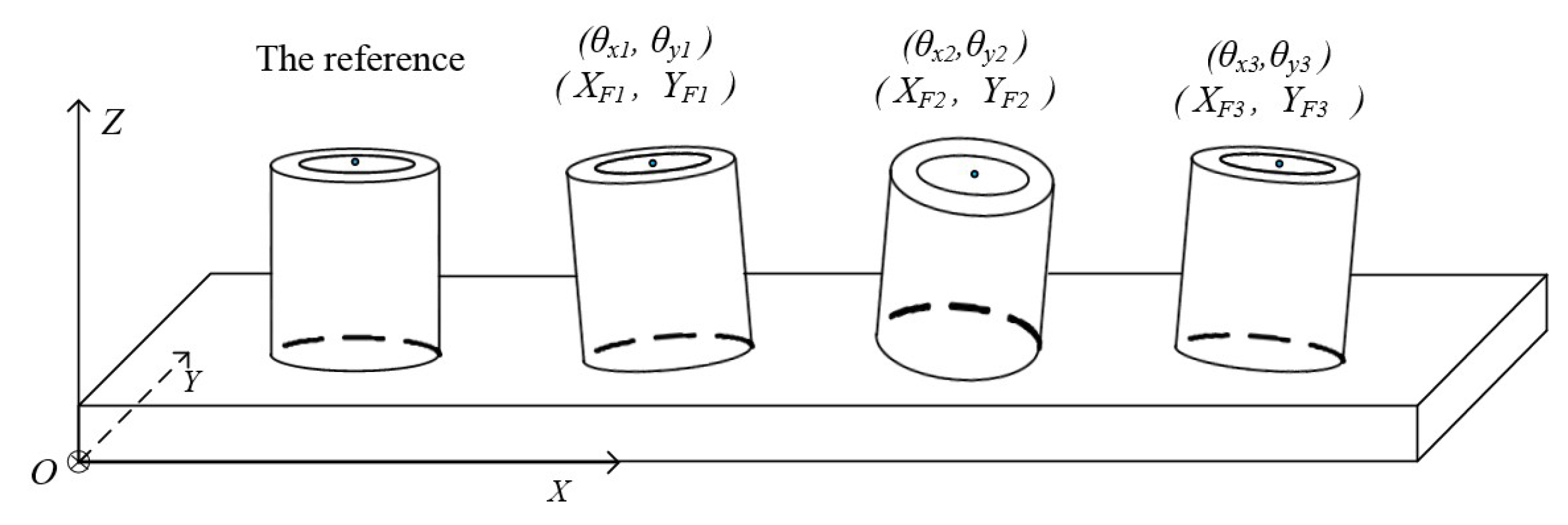
In order to identify the angle errors of machine tools, a high-accuracy angular standard should be provided by calibration. The workpiece coordinate system was established as shown in Figure 5, and the relative angles θ x i and θ y i are the tilt angles of the plane mirror of the i th target around the X-axis and Y-axis, respectively. The first target was selected as the reference target, and the angle of the other targets were determined relative to it. The calibration relative angles could be obtained through measurement compensated by laser interferometer.
The spot displacement on the image sensor was proportional to the angle of the reflective surface, i.e., each pixel corresponds to 2.27 arc seconds. Subpixel spot extraction can improve the angle resolution by one order of magnitude. By using an angle sensor to measure every plane mirror, the displacement between the spot reflected by each plane mirror and that reflected by the reference plane mirror can be obtained. Due to the surface error of a plane mirror, it is rational to compute the average value of multiple samplings. As such, the calibration relative angles could be obtained through measurement compensated by a laser interferometer with an angular lens.

3.2. Calibration of the Relative Position

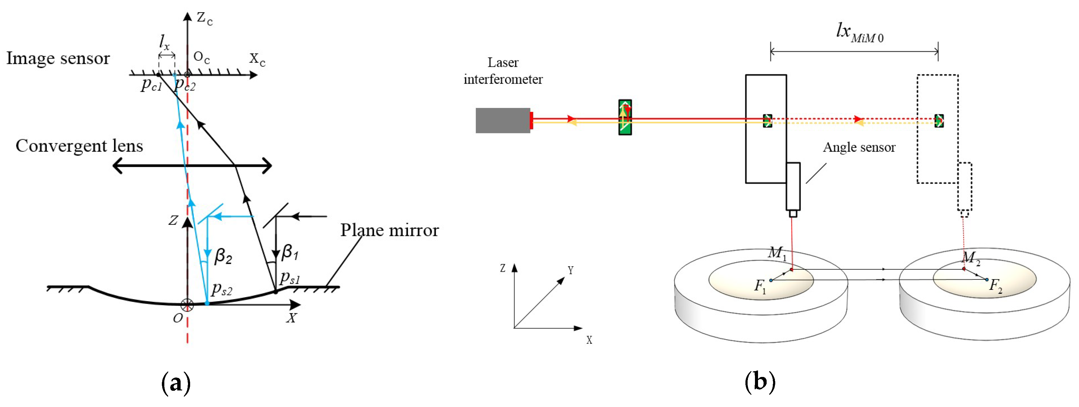
There is a point on every revolutionary paraboloid surface at which the tangent plane is parallel to the plane mirror around the revolutionary paraboloid. This point is defined as the feature point of the revolutionary paraboloid. To quantitatively determine the relative positioning of paraboloids, it can be defined as the relative positioning of the feature points of the corresponding paraboloids. Like the computation of the relative angle, the position of other targets was also found relative to the reference target, as shown in Figure 5. The displacement values X F i   and   Y F i are the relative position of the feature point of the i th target along the X-axis and Y-axis, respectively. As Figure 6a shows, when the angle sensor moves along the X-axis, the reflection point moves from p s 1 to p s 2 and the spot on the image sensor moves from p c 1 to p c 2 . In the same paraboloid, the translational displacement of the angle sensor, as mentioned above, is linearly related with the displacement of the spot on the image sensor. Besides this, the coefficient of linearity can be obtained by the measurement of the angle sensor on the revolutionary paraboloid. To conduct a large-scale measurement, the distances of the feature points of different revolutionary paraboloids should be determined.
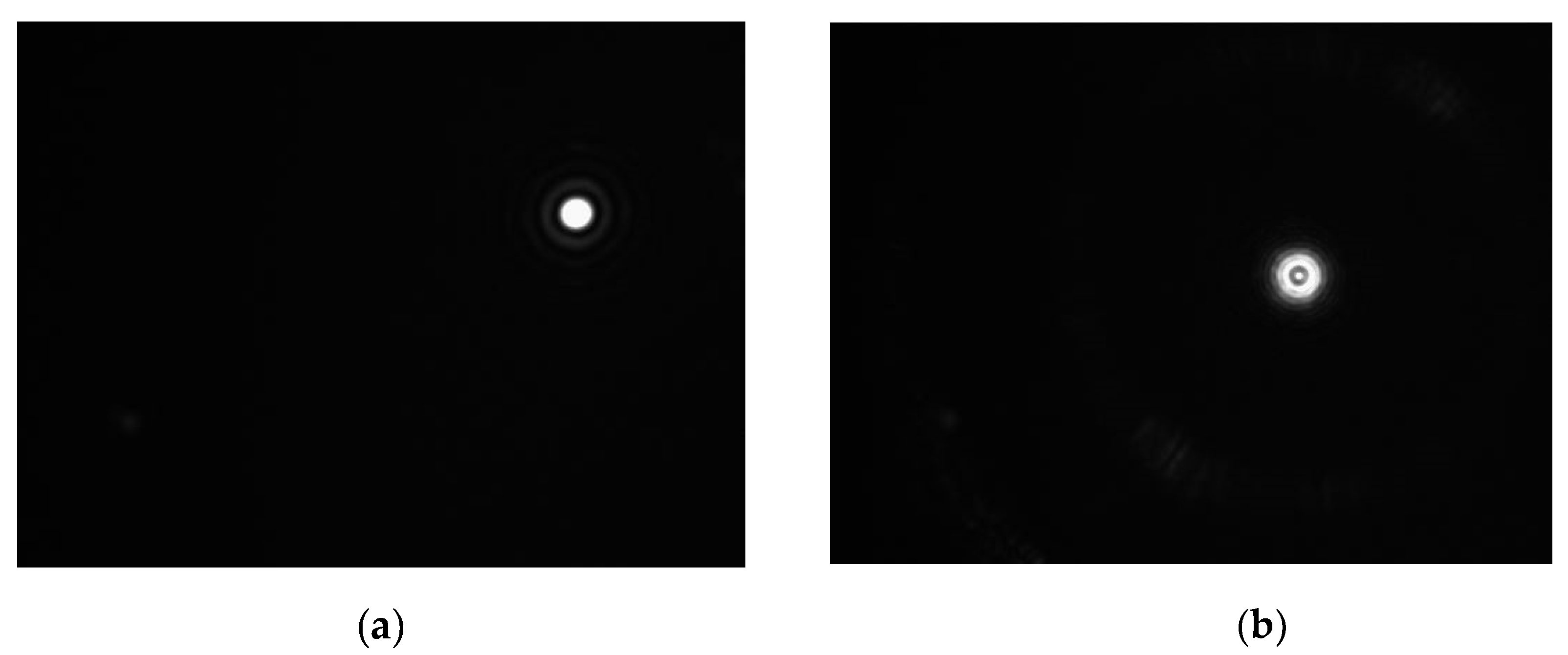
In order to calculate the relative positioning of feature points in the workpiece coordinate system, the machine drives an angle sensor from the measurement point M 1 to M 2 along the X-axis, as shown in Figure 6b. The points F 1 and F 2 are defined as the feature points of two revolutionary paraboloids. Spot images of the feature point and the measurement point are shown in Figure 7a,b. The position of the spot center is obtained by ellipse fitting, which can realize subpixel spot extraction. It was found by calibration that each pixel in the image corresponds to 2.27 arc seconds or 1.6 μ m , and the resolutions of the angle and position can reach, respectively, 0.2 arc seconds and 0.16 μ m by subpixel spot extraction. Actually, the spot image of a feature point cannot be obtained directly, so it is obtained by measuring the corresponding plane mirror.
As illustrated in Figure 6b, the vector relation between two feature points F 1 and F 2 is described by the following equation:
F 1 F 2 = F 1 M 1 + M 1 M 2 + M 2 F 2 .
In the X direction, we have:
( X F 2 X F 1 ) = ( X M 1 X F 1 ) + ( X M 2 X M 1 ) + ( X F 2 X M 2 ) ,
where X F 2   and   X F 1 are the X coordinates of feature points F 1   and   F 2 in the object ordinate system, and X M 2   and   X M 1 are the X coordinates of measuring points M 1 and M 2 in the object ordinate system. Through measurement by laser interferometer with a position lens or machine tools with higher precision, l x M 2 M 1 , defined as the distance between measuring points M 1 and M 2 , can be calculated. In addition, the distance between the measurement point and the feature point in a revolutionary paraboloid can be determined based on the spot displacement in an image by the following equation:
( X M i X F i ) = k ( x M i x F i ) ,
where k is the conversion coefficient from spot displacement to actual displacement calibrated by a laser interferometer; X M i   and   X F i are the X coordinates of the measurement point and feature point of the i th revolutionary paraboloid in the object coordinate system; and x M i   and   x F i are the X coordinates of the measurement point and feature point of the i th revolutionary paraboloid in the image system.
Since the aim of the computation of the relative positioning was to obtain the position of each feature point relative to the feature point of the reference revolutionary paraboloid, the X coordinate X F 0 of the feature point of the reference revolutionary paraboloid was equal to 0. Therefore, in the X direction, the relative position of the feature point of the i th revolutionary paraboloid can be calculated as follows:
X F i = k ( x M 0 x F 0 ) + l x M i M 0 + k ( x F i x M i ) .
Similarly, in the Y direction, we have:
Y F i = k ( y M 0 y F 0 ) + l y M i M 0 + k ( y F i y M i ) .
In these equations, X F i and Y F i represent the relative position of the i th feature point in the object system. Besides this, x M 0 , y M 0 , x M i , y M i ,   x F 0 , y F 0 , x F i , and y F i are the coordinates of the spot in the image system, and l x M i M 0 and l y M i M 0 are, respectively, the displacement in the X direction and the Y direction measured by laser interferometer or machine tools with higher precision.

3.3. Calculation of the 6 Degrees-of-Freedom Errors

By the method mentioned in Section 3.1 and Section 3.2, the relative angles θ x i   and   θ y i and position X F i and Y F i of the i th target were calibrated. To ensure repeatability of the measurement system, the angle difference between the first and the last plane mirror should be, where possible, the same as the angle difference of calibration. The alignment can be conducted based on the spot position in the image, which can reduce the cosine error of the measurement effectively. When the 1-D artifact was located on the X-axis of the machine tool horizontally, the measurement value of the relative angles θ x i   and   θ y i and relative position X F i and Y F i of the i th target could be obtained by the machine tool to be tested. In the process of measurement, l x M i M 0 and l y M i M 0 should be computed by the feedback value of the machine tool. That means that X F i , Y F i are obtained by the following equations:
X F i = k ( x M 0 x F 0 ) + ( X M i X M 0 ) + k ( x F i x M i ) ,
Y F i = k ( y M 0 y F 0 ) + ( Y M i Y M 0 ) + k ( y F i y M i ) ,
where x M 0 , y M 0 , x M i , y M i ,   x F 0 , y F 0 , x F i , and y F i are the coordinates of the spot in the image system when measuring horizontally, and X M 0 , X M i , Y M 0 , and Y M i are the measured coordinates of the measurement point in the machine coordinate system.
Due to geometric errors in the linear motion of the machine tool, the relative angle and position measured by the machine tool are not the same as the calibration values. The roll error ε x ( x ) and pitch error ε y ( x ) are caused by deviation in the relative angles and the position error δ x ( x ) and horizontal straightness error δ y ( x ) are caused by deviation in the relative position. Thus, by calculating the deviation between the measurement values and calibration values, these errors at the target positions can be identified.
The roll error ε x ( x ) and the pitch error ε y ( x ) at the target position can be identified by the following equations:
ε x ( x ) = θ x i θ x i ,
ε y ( x ) = θ y i θ y i .
Due to the character of a revolutionary paraboloid, the displacement difference measured by the machine tool includes coupling of angle errors. Hence, the position error δ x ( x ) at the target position can be identified by the following equation:
δ x ( x ) = X F i X F i k m ε y ( x F i ) ,
where k and m represent the conversion coefficients from spot displacement in the image to actual displacement and from angle variation to spot displacement in the image, respectively, and ε y ( x F i ) is the pitch error at the target position.
Similarly, the horizontal straightness error δ y ( x ) can be identified by the following equation:
δ y ( x ) = Y F i Y F i k m ε x ( x F i ) .
When the 1-D artifact is located vertically, the measurement values of the relative angles θ x i and θ x i and relative position X F i and Y F i of the i th target can be obtained by the following equations:
X F i = k ( x M 0 x F 0 ) + ( X M i X M 0 ) + k ( x F i x M i ) ,
Y F i = k ( y M 0 y F 0 ) + ( Z M i Z M 0 ) + k ( y F i y M i ) ,
where x M 0 , y M 0 , x M i , y M i ,   x F 0 , y F 0 , x F i , and y F i are the coordinates of the spot in the image system when measuring vertically. Unlike horizontal layouts, the Y coordinates of each target are calculated based on the displacement in the Z direction of the machine. Thus, the X coordinates X M 0   and   X M i and the Z coordinates Z M 0   and   Z M i of the measurement point in the machine coordinate system were used to compute the relative positions of targets.
Similarly, the yaw error ε z ( x ) and the vertical straightness error δ z ( x ) , instead of the pitch error ε y ( x ) and horizontal straightness error δ y ( x ) , are caused by deviation in the relative angle θ y i and position Y F i . Therefore, the yaw error ε z ( x ) can be identified by the equation:
ε z ( x ) = θ y i θ y i ,
and the vertical straightness error δ z ( x ) can be identified by the equation:
δ z ( x ) = Y F i Y F i k m ε x ( x F i ) .
Thus, the 6 degrees-of-freedom errors of a linear motion guide rail can all be identified.
4. Experiment

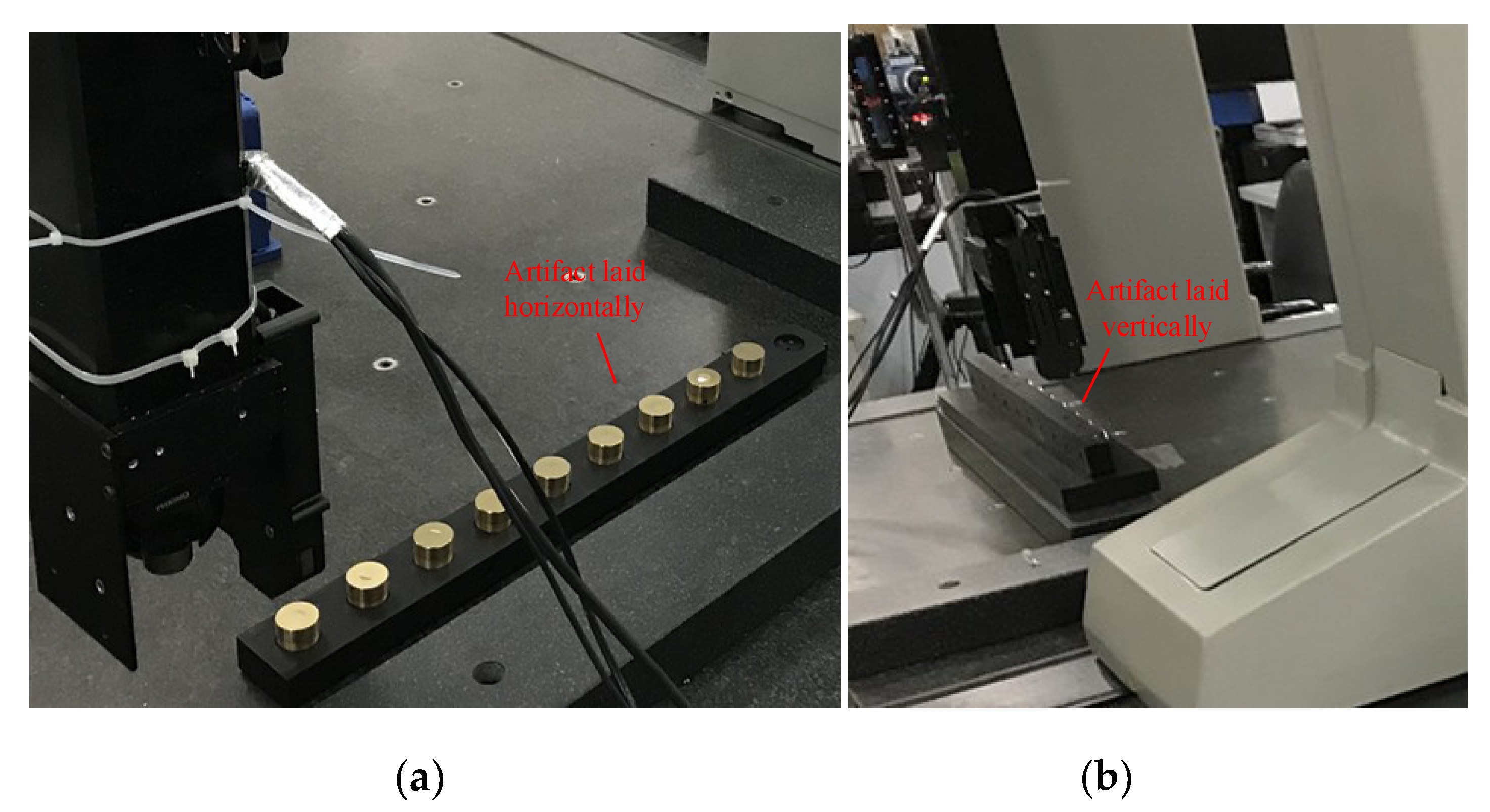
Experiments in the X direction were carried out in a CMM, and Figure 8a shows the measurement setup when the 1-D artifact was located horizontally. Through this measurement, two angle errors and two position errors were identified.
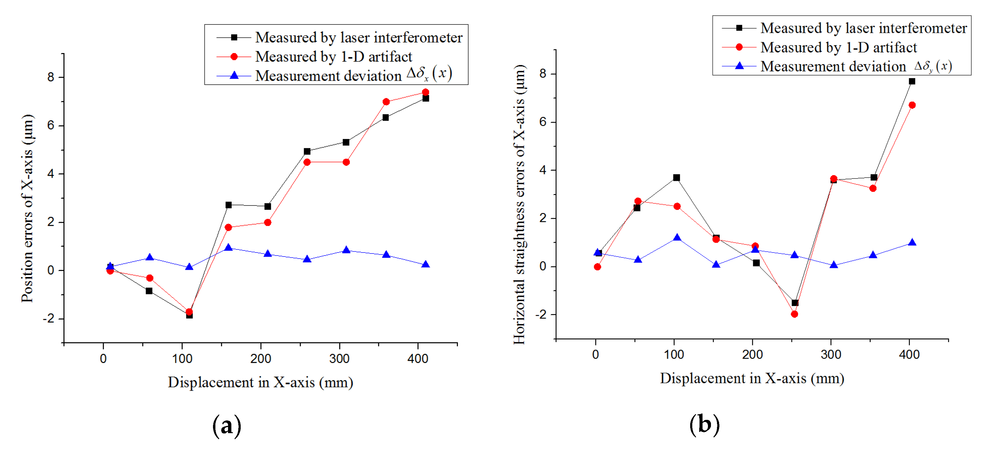
The calculated results of the position error δ x ( x ) and the horizontal straightness error δ y ( x ) identified through measurement using the 1-D artifact and laser interferometer are shown in Figure 9a,b. The type of the laser interferometer was an SJ6000, produced by Chotest.
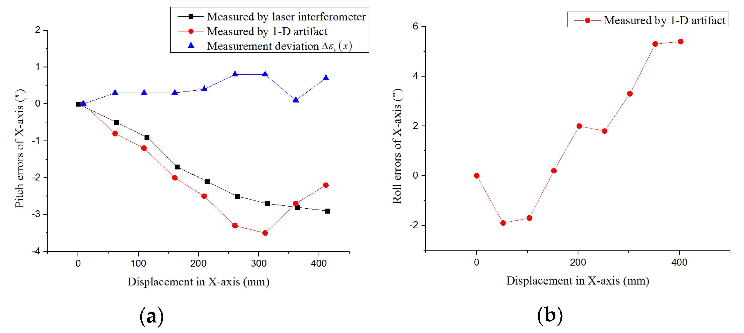
The results of the pitch error ε y ( x ) and the roll error ε x ( x ) are shown in Figure 10a,b. Since the laser interferometer cannot identify the roll error of the machine tool, the measurement result of the roll error was not compared with that measured by laser interferometer.
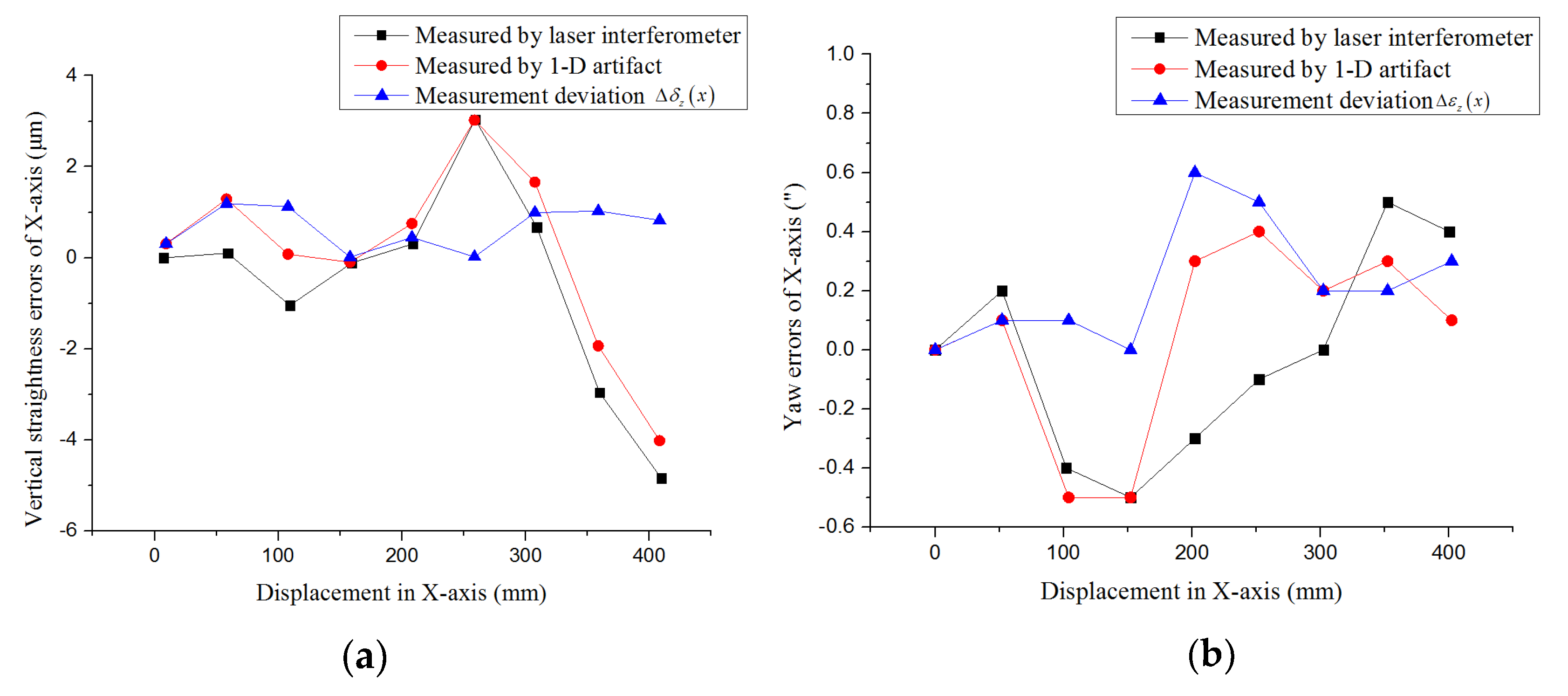
For a vertically oriented 1-D artifact, Figure 11a,b illustrates the calculated results of the vertical straightness error δ z ( x ) and the yaw error ε z ( x ) measured using the 1-D artifact and a laser interferometer.
By comparing the geometric errors of linear motion of the machine tools measured using a 1-D artifact with those obtained using a laser interferometer, it could be seen that the maximum measurement deviation and mean measurement deviation of the position errors were 1.2 μ m and 0.57 μ m , while the maximum measurement deviation and mean measurement deviation of the angle errors were 0.8” and 0.32”, which might be caused by processing errors of the revolutionary paraboloids and plane mirrors.

5. Conclusions

This article presented an innovative method for the measurement of geometric errors in the linear motion of CNC machine tools. The main innovation was the combination of revolutionary paraboloids and plane mirrors in an array. The former realized the measurement of position and angle, and the latter expanded the measurement range significantly, which made it possible for the method to be applied in error detection for machine tools. In addition, the measurement mechanism and the principle of identifying geometric errors were described in detail. By locating the 1-D artifact horizontally and vertically, a total of six geometric errors of a guide rail moving along the X direction were identified. By comparing with measurement results obtained using a laser interferometer, the feasibility and practicability were confirmed. Incidentally, the measurement system based on the new 1-D artifact could also be applied to identify the squareness errors of machine tools. An L-shaped artifact could be produced by stitching two 1-D artifacts together to include two-dimensional information of different vertical directions in order to measure the squareness.
Due to the measurement mechanism, the identification of straightness errors and angle errors did not demand good repeatability of the pose in the workspace. That means the result of these errors would not vary obviously if the pose of the 1-D artifact did not change significantly. However, the positioning error, because of its distribution along the X-axis, was sensitive to the pose of the 1-D artifact. Thus, we obtained the relative position of each target in the workpiece coordinate system to weaken this influence, i.e., to reduce the error caused by lateral tilt of the 1-D artifact from first-order error to second-order error (cosine error). However, the error caused by vertical tilt of the 1-D artifact could not be eliminated. Hence, when the levelness of the machine tool bed is inferior, identification of the positioning error based on this method will not show such good performance. This is also the reason why we selected horizontal measurement to identify the positioning error of machine tools.
Besides this, the accuracy of position and angle measurement using this method could also reach a fairly high standard, and the rapidity, scalability, and operability of the method make it easy to automate and integrate. Due to the advantages of a noncontact measurement, the measurement time of an axis based on the method proposed is less than two hours if data processing is automated. Thus, this method has considerable value and potential.

Author Contributions

F.F. and X.L. proposed the method; X.W. designed the measurement experiments and wrote the paper; X.Y. and Z.L. developed system software and processed the data; Z.S. and Z.Y. designed optical structure; H.Z. modified the paper.

Funding

This research was financially supported by the National Natural Science Foundation of China (NSFC) (No: 51775378), the National Key R&D Program of China (No.2017YFF0108102) and Natural Science Foundation of Shanxi Province, China (Grant No. 201801D121180).

Conflicts of Interest

The authors declare no conflict of interest.

References

  1. Liu, H.; Hua, X.; Chen, J.; Rui, Y. Measurement and compensation of machine tool geometry error based on Abbe principle. Int. J. Adv. Manuf. Technol. 2018, 98, 2769–2774. [Google Scholar] [CrossRef]
  2. Wang, X.; Liu, S.; Zhang, G.; Wang, B. Error analysis of the articulated flexible arm CMM based on geometric method. In Proceedings of the Sixth International Symposium on Instrumentation and Control Technology, Beijing, China, 6 November 2006. [Google Scholar]
  3. Xiang, S.; Li, H.; Ming, D.; Yang, J. Geometric error identification and compensation for non-orthogonal five-axis machine tools. Int. J. Adv. Manuf. Technol. 2018, 96, 2915–2929. [Google Scholar] [CrossRef]
  4. Pan, F.; Li, N.; Bai, Y.; Wang, X.; Wu, X. Geometric errors measurement for coordinate measuring machines. Iop Conf. Ser. Earth Environ. Sci. 2017, 81, 012117. [Google Scholar] [CrossRef] [Green Version]
  5. Zhang, G.X. Coordinate Measuring Machines; Tianjin University Press: Tianjin, China, 1999; pp. 405–425. [Google Scholar]
  6. Giacomo, B.D. Calibration of Positional Errors in Coordinate Measuring Machines and Machine Tools Using a Laser Interferometer System. Appl. Mech. Mater. 2015, 798, 303–307. [Google Scholar] [CrossRef]
  7. Anke, G.; Dirk, S.; Gert, G. Self-Calibration Method for a Ball Plate Artefact on a CMM. CIRP Ann. 2016, 65, 503–506. [Google Scholar]
  8. Weikert, S. R-Test, a New Device for Accuracy Measurements on Five Axis Machine Tools. CIRP Ann. Manuf. Technol. 2004, 53, 429–432. [Google Scholar] [CrossRef]
  9. Ibaraki, S.; Oyama, C.; Otsubo, H. Construction of an error map of rotary axes on a five-axis machining center by static R-test. Int. J. Mach. Tools Manuf. 2011, 51, 190–200. [Google Scholar] [CrossRef] [Green Version]
  10. Masashi, Y.; Hamabata, N.; Ihara, Y. Evaluation of Linear Axis Motion Error of Machine Tools Using an R-test Device. Procedia. Cirp. 2014, 14, 311–316. [Google Scholar] [CrossRef] [Green Version]
  11. Cheng, F.; David Lee, B. An innovative method for coordinate measuring machine one-dimensional self-calibration with simplified experimental process. Rev. Sci. Instrum. 2013, 84, 139–144. [Google Scholar]
  12. Tsutsumi, M.; Saito, A. Identification and compensation of systematic deviations particular to 5-axis machining centers. Int. J. Mach. Tools Manuf. 2003, 43, 771–780. [Google Scholar] [CrossRef]
  13. Zhong, G.; Wang, C.; Yang, S.; Zheng, E.; Ge, Y. Position geometric error modeling, identification and compensation for large 5-axis machining center prototype. Int. J. Mach. Tools Manuf. 2015, 89, 142–150. [Google Scholar] [CrossRef]
  14. Wu, B.; Yin, Y.; Zhang, Y.; Luo, M. A new approach to geometric error modeling and compensation for a three-axis machine tool. Int. J. Adv. Manuf. Technol. 2018. [Google Scholar] [CrossRef]
  15. Lv, Z.; Li, X.; Su, Z.; Zhang, D.; Yang, X.; Li, H.; Li, J.; Fang, F. A Novel 2D Micro-Displacement Measurement Method Based on the Elliptical Paraboloid. Appl. Sci. 2019, 9, 2517. [Google Scholar] [CrossRef]
  16. Sun, H.; Geng, A.-H.; Zhang, H.-B.; Wang, X. Precision Angle-Measuring System Based on Linear CCD. MicroComput. Inf. 2009, 25, 61–62. [Google Scholar]
Figure 1. The 6 degrees-of-freedom errors of the X-axis.
Applsci 09 03357 g001
Figure 2. (a) Sketch of the 1-D artifact; and (b) sketch of the measurement target.
Applsci 09 03357 g002
Figure 3. An illustration of the method of measuring the optical path.
Applsci 09 03357 g003
Figure 4. (a) Horizontal measurement with respect to the X-axis; and (b) vertical measurement with respect to the X-axis.
Applsci 09 03357 g004
Figure 5. Sketch of the relative angle and position of targets.
Applsci 09 03357 g005
Figure 6. (a) Relative displacement measurement in one revolutionary paraboloid; and (b) relative position measurement of feature points on different revolutionary paraboloids.
Applsci 09 03357 g006
Figure 7. (a) Spot image of the feature point (by measuring the corresponding plane mirror); and (b) spot image of the measurement point on a revolutionary paraboloid.
Applsci 09 03357 g007
Figure 8. (a) Measurement horizontally; and (b) measurement vertically.
Applsci 09 03357 g008
Figure 9. (a) The position errors of the X-axis; and (b) the horizontal straightness errors of the X-axis.
Applsci 09 03357 g009
Figure 10. (a) The pitch errors of the X-axis; and (b) the roll errors of the X-axis.
Applsci 09 03357 g010
Figure 11. (a) The vertical straightness errors of the X-axis; and (b) the yaw errors of the X-axis.
Applsci 09 03357 g011