Abstract
With the increasing global concerns about the impacts of byproducts from the combustion of fossil fuels, researchers have made significant progress in seeking alternative fuels that have cleaner combustion characteristics. Such fuels are most suitable for addressing the increasing demands on combustion-based micro power generation systems due to their prominently higher energy density as compared to other energy resources such as batteries. This cultivates a great opportunity to develop portable power devices, which can be utilized in unmanned aerial vehicles (UAVs), micro satellite thrusters or micro chemical reactors and sensors. However, combustion at small scales—whether premixed or non-premixed (diffusion)—has its own challenges as the interplay of various physical phenomena needs to be understood comprehensively. This paper reviews the scientific progress that researchers have made over the past couple of decades for the numerical investigations of diffusion flames at micro scales. Specifically, the objective of this review is to provide insights on different numerical approaches in analyzing diffusion combustion at micro scales, where the importance of operating conditions, critical parameters and the conjugate heat transfer/heat re-circulation have been extensively analyzed. Comparing simulation results with experimental data, numerical approaches have been shown to perform differently in different conditions and careful consideration should be given to the selection of the numerical models depending on the specifics of the cases that are being modeled. Varying different parameters such as fuel type and mixture, inlet velocity, wall conductivity, and so forth, researchers have shown that at micro scales, diffusion combustion characteristics and flame dynamics are critically sensitive to the operating conditions, that is, it is possible to alter the flammability limits, control the flame stability/instability or change other flame characteristics such as flame shape and height, flame temperature, and so forth.
1. Introduction
With the recent technology advancements over the past few decades, the development of integrated devices at micro scales, known as Micro Electro-Mechanical Systems (MEMS), has been widely recognized and used in various industries. In order for such systems to work, an external power source is required, which is typically batteries. However, the low energy density of batteries and the weight limitations in MEMS devices have convinced researchers to seek alternative efforts in the power generation at small scales and take advantage of the extremely higher energy densities of hydrocarbon fuels through micro combustors [1]. However, combustion-related power generation in micro scales has its own challenges as it is not trivial to obtain a stable flame. This is essentially attributed to (a) the low residence time inside of the micro combustor to complete the combustion process and (b) the higher heat losses from the combustion chamber walls due to the larger surface to volume ratios [1,2].
Designing and conducting numerous micro-scale experiments are both time consuming and expensive. Therefore, it is more reasonable to direct most of the efforts towards numerical simulations and to limit experimental investigations to when it is necessary especially for validation purposes. Hence, the literature in combustion fields is very rich with numerical methodologies and simulations that have been conducted to investigate combustion physics at micro scales and seek ways to (a) develop more proficient and accurate numerical models, (b) capture different phenomena in micro-scale combustion and (c) optimize micro-scale power generation devices.
In the last two decades, significant efforts have been invested in the modeling of the micro-scale combustion devices, through which numerous methodologies have emerged and prominent conclusions have been drawn for different operating conditions such as different fuel types and phases, different geometries, different fuel/oxidizer compositions, and so forth. Currently, such numerical methodologies and simulation tools are widely adopted to conduct research in micro combustion. With that, most micro-combustion studies consist of numerical simulations to complement the experimental research, allowing a better understanding of the dynamics of the flames and the optimization of the corresponding devices.
Numerical simulations for both premixed and non-premixed (diffusion) combustion at micro scales have been evolving extensively as the topic is becoming more and more interesting to researchers. In premixed combustion, researchers have concluded that combustion characteristics and flame behavior are very sensitive to the dimensional and thermo-physical parameters [3,4,5,6]. Other than premixed combustion at micro scales, non-premixed or diffusion combustion at such scales has also been under great attention due to the fact that diffusion combustion is a more typical combustion regime to use in practical systems [7]. By comprehending the effects of the complex transport phenomena associated with the chemical kinetics of such flames, researchers can further investigate complex phenomena such as flame ignition and extinction and pollution formations and eventually improve the efficiency of combustion-oriented devices such as combustion engines [8].
In this review paper, the authors will present a succinct review of the progress that has been made in numerical investigations and methodologies on the topic of diffusion combustion at micro scales, where a summary of the state of the art will be provided to further direct researchers on adding to the body of knowledge in this field.
2. Governing Equations
The main governing equations used for the numerical simulations are the conservation equations for a continuous, compressible, multi-component and thermally-perfect gas mixture for laminar flows. It is noted that the numerical simulations for combustion at micro scales do not concern turbulence as the flow is usually laminar due to the small scales of the problems. The conservation equations of total mass, momentum, species mass fractions and energy are presented below, respectively [9].
Here, t, , , , and represent time, the mixture density, the pressure, the mixture velocity vector, the stress tensor, the fluid stress tensor, and the acceleration vector due to gravity, respectively. is the total number of species, T is the temperature, and , , , and are the mass fraction, the diffusion velocity, the formation rate, the enthalpy and the net production rate of the kth species, respectively. represents the specific heat coefficients. The gas mixture is assumed to be an ideal gas and its density is calculated through the equation of state.
The diffusion velocities of species k are calculated from Fick’s law and the thermal diffusion effect:
where, , , and are the mole fraction, the thermal diffusion and the mixture-averaged diffusion coefficient of species k.
The heat flux vector, , is defined as:
where is the mixture thermal conductivity, is the radiative heat transfer. However, in some studies the radiative heat transfer is neglected, due to the lower impact at micro scale [2].
The radiative heat transfer can be modeled by assuming the optically thin radiation hypothesis, in which the self-absorption of radiation is neglected. The radiative heat transfer contribution in the energy equation is described as:
where, is the environment temperature, is the Stefan-Boltzmann constant and is the Planck mean absorption coefficient.
The initial numerical studies of micro diffusion combustion did not consider the wall thermal effects and, as a consequence, the numerical results close to the flame edge shifted away from those of the experiments, showing the important impact of the wall quenching in that region, and the importance of the thermal interactions between the solid and the fluid. For this reason, the numerical studies started to incorporate the energy equation for the solid region, using conjugate heat transfer condition for the fluid-solid interaction.
3. Numerical Studies of Micro-Diffusion Flames
The numerical studies of micro-diffusion flames have emerged with the aim of better understanding the physical phenomena of diffusion combustion at micro scales, where it is challenging to collect such comprehensive data through experimental investigations.
Nakamura et al. performed numerical simulations to investigate the impacts of the fuel velocity on micro flame structures in laminar methane-air combustion [10]. In their simulations, they used both one-step and detailed reaction mechanisms and were able to capture the flame heights, temperature and the methane and oxygen concentration distributions in an acceptable agreement with the experimental measurements for different inlet velocities. Through simulation results, they could capture a linear correlation between the flame height and the methane flow rate, that was consistent with the observations in the experimental data as represented in top plot of Figure 1. The contours illustrated in the bottom of this figure compare the simulation results (flow vectors (a), temperature contours (b), methane and oxygen concentrations (c) and reaction contours (d)) for two different methane inlet velocities. This work also reported on the limited buoyancy effect on the flow field (the order of 10 m/s), when compared with the minimum fuel velocity of 1 m/s, and a flame temperature difference of 700 K (temperature difference between the flame edge at the vicinity of the flame base and the adiabatic temperature). Such predictions were not as exact near the flame edge, where the impacts of wall quenching and detailed finite-rate chemical kinetics become more significant.
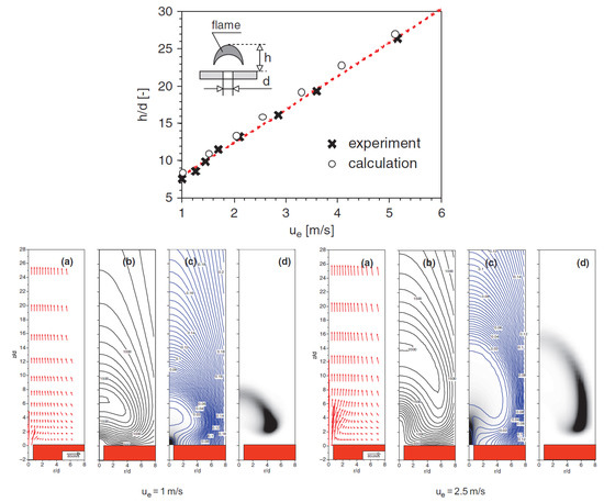
Figure 1.
Comparison between experimental and numerical simulations of a micro diffusion flame using methane and air by Nakamura et al. [10]. Top: Simulation results against experimental data of the flame height as a function of the methane inlet velocity, ; Bottom: 2D profiles of the simulation results for and 2 m/s: (a) flow vectors, (b) temperature contours, (c) methane and oxygen concentrations ratio, and (d) reaction contours.
Subsequently, Nakamura et al. conducted a numerical study to investigate the impacts of the burner size on the extinction behaviour of methane diffusion flames at micro scales [11]. They used a convective–diffusive heat and mass transport model, where the combustion reaction was assumed by a one-step, irreversible, exothermic reaction. In order to take the near-extinction effects into account, they selected and validated specific kinetics constants. Using the Damkohler principle, they concluded that “there is the minimum burner diameter for the micro flame to exist” [11]. As represented in the left diagram of Figure 2, the normalized flame height and radius (both are normalized by the burner diameter) and the scalar dissipation rate (SDR) at the maximum heat release rate location under the same Reynolds (Re) number, are plotted against the burner diameters. The SDR, or diffusive transport process rate, , defined by the derivative of the mixture fraction, Z, based on inert gas normal to the flame surface, n, and multiplied by a non-dimensional diffusion coefficient, D, showed to be smaller than the chemical reaction rate (CRR) for mm, and about the same order of the chemical reaction rate for mm. It is shown that for mm, the SDR, flame height and flame radius decrease rapidly with the increase of the burner diameter. However, for mm, all three parameters experience a more smooth transition with the change of the burner diameter. Reducing the burner diameter further toward the limits, the SDR exceeded the chemical reaction rate and led to extinction. This work illustrates that the the crossover between the SDR and the CRR can be defined by a critical Damkohler () number, which is representative of the ratio of the diffusion time and the chemical time, i.e., the flame is controlled by diffusion or chemical process, in case of number or number, respectively. Investigating the impacts of different inlet methane velocities in three different burner diameters (, and mm) on the flame extinction behavior, they also showed the existence of a critical minimum flame height and a critical maximum heat release rate, at which the flame can experience extinction, regardless of the burner diameter as presented in the right diagram of Figure 2.
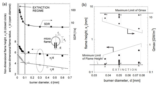
Figure 2.
Numerical study of methane micro diffusion flame to analyze the burner size effects by Nakamura et al. [11]. (a): Size effects on flame shapes and scalar dissipation rate (SDR) evaluated at the location of maximum heat release rate; (b): Minimum flame height and corresponding maximum local heat release rate, .
Using a different fuel, Cheng et al. investigated the combustion characteristics of hydrogen diffusion flames at micro-scale, both experimentally and numerically [12]. In their experiments, they implemented non-intrusive techniques to measure all major species concentrations (, , , ) and, for the first time, the absolute hydroxyl radical concentration (OH), together with the temperature, at with inner diameters of 0.2 mm and 0.48 mm for the tube injector fuel (Figure 3). The OH images illustrated a spherical flame forming with reducing the tube diameter. Furthermore, flames were found to be in the convection–diffusion controlled regime due to the low Peclet (Pe) number, indicating the insignificant effect of Pe number on the flame shape. In the numerical simulations, they applied detailed transport and multi-step reaction mechanisms with 9 species and 21 reactions for hydrogen–air combustion with the following boundary conditions: non-slip, non-catalytic reactions, and constant wall temperature (300 K). These numerical simulations were, however, unable to correctly predict the flame structure for the domains with dominant air entrainment and thermal-diffusive effects. This was later addressed by Cheng et al. [13], where the burner was coupled to the computational domain to solve for the properties both inside and outside of the burner wall and to allow for taking the conjugate heat transfer and the back-diffusion of the species into account. More specifically, they obtained the wall temperature distribution by solving the energy balance of diffusive, convective and conductive fluxes into the gas flow and imposed that in their numerical calculations.
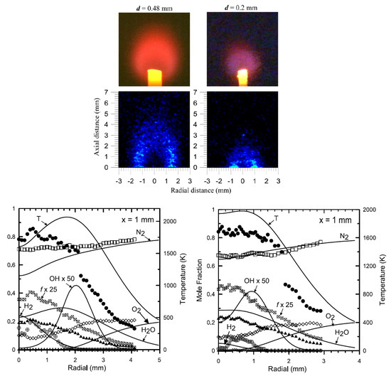
Figure 3.
Experimental and numerical study of hydrogen micro-diffusion flame for different tube diameters by Cheng et al. [12]. Top: Photographs and single-pulse LIPF-OH (Laser Induced Predissociative Fluorescence - OH radical) (a pre-dissociation fluorescence technique to collect densities of OH radicals) images of the microscale hydrogen diffusion flames with tube diameters of 0.2 and 0.48 mm; Bottom: Comparison of measured mean temperature, major species, and OH mole fraction with calculated radial profile for mm (bottom-left) and mm (bottom-right) flame at mm.
Moving forward with their previous work, Cheng et al. [8] conducted detailed measurements and assessments of laminar hydrogen jet flames through non-intrusive experimental techniques and compared the findings with computational results. They investigated non-premixed reactive flows with different Reynolds () numbers ( and ). As presented in Figure 4, it was observed that the impact of the thermal diffusion on the flame structure is more pronounced at the case with higher Re number. In addition to varying numbers, Cheng et al. examined the flame structure at with five different chemical kinetic mechanisms and did not observe any major differences among them. The effects of the burner wall on the flame structure were also studied, using a commercial CFD (Computational Fluid Dynamics) code, CFD-ACE [14], which was found to affect the flows with a lower number more considerably. It was also concluded that a variable wall temperature profile as a boundary condition would result in a better agreement between the computed and measured data. The complete measurements of laminar hydrogen jet diffusion flames in this work can be used as benchmarks for the development and validation of CFD codes.
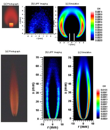
Figure 4.
Experimental (a and b in both top and bottom figures) and numerical (c in both top and bottom figures) study of hydrogen micro-diffusion flame for different Reynolds numbers by Cheng et al. [8]. (a) Photograph, (b) single-pulse LIPF-OH image and (c) computed OH isopleths of the hydrogen jet diffusion flame, Top: ; Bottom: .
Chen et al. continued the research that was initially pursued by Nakamura et al. [10] by conducting experimental and numerical analyses of the structure and stabilization mechanism of a micro jet methane diffusion flame at near extinction conditions, especially in the standoff region [13] (see Figure 5). The numerical simulations were conducted by the simulation tool CFD-ACE [14], where the energy balance of conductive, diffusive, and convective fluxes in the gas flow with thermal conduction at the wall are solved to compute the wall temperature profile. Similar to the previous work [8], the radiation heat loss was neglected and non-slip and non-catalytic reaction conditions were applied on the burner surface. The code was validated through initial simulations at different tube diameters (0.148 mm, 0.4 mm and 1.0 mm) and fuel exit velocities. The stoichiometric mixture fraction at the symmetric jet center line was common in all cases. The simulations were able to capture flame heights as measured in the experimental results, where the flame height increased with the increase of the exit velocity, for all tube diameters. In terms of the prediction of the micro-flame stabilization characteristics, CH mass fraction isopleths were also in good agreement with those of measurements (Figure 5). They also made a comparison between CH contours of adiabatic and variable wall temperature conditions and observed that, with the adiabatic wall, the flame tends to extend farther upstream to the port and anchor on the tube. However, in the case of variable wall temperature, the flame quenched on the tube wall resulting in a gap. Subsequently, the heat transfer through the wall led to accelerated fuel decomposition and chain-branching reactions. They also suggested that the role of the buoyancy becomes important in flames with larger tube diameters and fuel velocities. On the other hand, for lower tube diameters, mm, and inlet velocities <3.68 m/s, the buoyancy effect becomes less important and the flame is controlled only by diffusion.
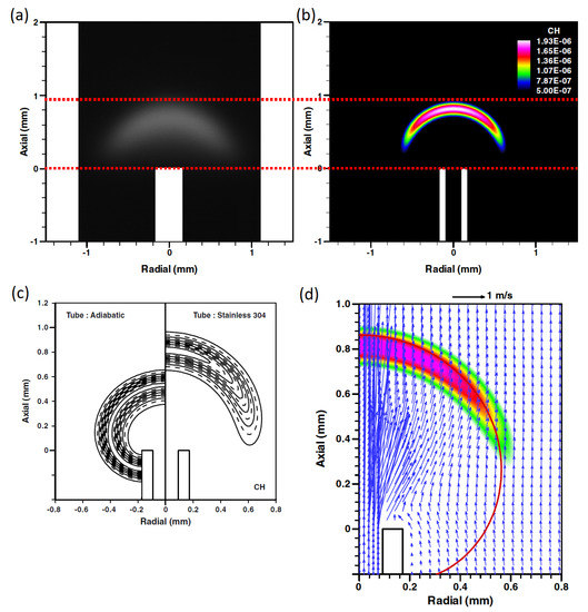
Figure 5.
Numerical study of a microjet methane diffusion flame near extinction by Chen et al. [13]. Top: Comparison of the measured CH* image (a) with computed CH mass fraction isopleths (b); Bottom: Comparison of CH contours calculated with adiabatic and variable wall temperature conditions (c), and Computed 2-D velocity vector coupled with CH isopleths in the standoff region (d).
The design of micro combustors has always been the main concern in order to increase their efficiency and stability. One of the first attempts to stabilize and enhance a methane diffusion flame in micro combustors was made by Badra and Masri [15]. They simulated different 2D and 3D designs to optimize the mixing fractions of the methane and air streams and obtain the stability conditions for the flame. To do so, they examined various inlet temperatures, multiple chamber inner materials (changing the conductivity), and reducing the external heat losses. With varying the materials inside the chamber, it was verified that the material with higher thermal conductivity allowed for stronger and more stable flames. This is attributed the fact that more conductive materials allow for more heat transfer to the incoming mixtures, which results in increasing their temperature to 100–300 C. On the other hand, for an adiabatic micro reactor with inlet mixtures at ambient temperature, they observed that the flame could not sustain. As shown in Figure 6, they also suggested that the optimal design to ensure suitable mixing would require a restriction at the inlet of the combustion chamber to help the incoming streams converge while introducing a minor pressure drop. It is noted that the simulations in this work were conducted using the commercial CFD tool ANSYS Fluent [16], where the authors took the thermal diffusion effects into account.
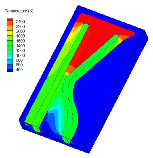
Figure 6.
Numerical study of micro-combustor design for optimization of methane and air mixing by Badra and Masri [15]. 3D Temperature contours using aluminum as the conductive material.
To further understand the importance of conjugate heat transfer for the inlet mixture and the negative role of the external heat losses, Li et al. investigated the diffusion combustion of liquid heptane in a small tube with and without heat recirculation via both experimental and numerical approaches [17]. They demonstrated that it was possible to reach a stable flame even without heat recirculation. Analyzing the impacts of equivalence ratio and the external heat loss coefficient, they observed the reaction zone moving with the variations of equivalence ratio; i.e., the reaction zone moves farther upstream when decreasing the equivalence ratio. The flame position was found to be sensitive to the heat recirculation as well, where no heat recirculation (adiabatic) resulted in the flame formation closer to the tube exit as compared to the cases with the existence of heat recirculation (more details are presented in Figure 7). In terms of the flammability limits, the numerical simulations showed that with the increase of the external heat loss, the flammability limit falls down rapidly if there is no heat recirculation. On the other hand, even for higher values of external heat loss coefficient (e.g., 100 W/m-K), the burner can sustain at the presence of heat recirculation. It is noted that with the heat recirculation, the wall temperature of the inner tube reaches temperatures higher than the boiling point of the liquid n-heptane, which results in the pre-evaporation of the liquid fuel. Otherwise, the liquid fuel would be accumulated in the tube. Numerical simulations in this work were performed by the commercial CFD tool ANSYS Fluent [16], where the effects of solid and gas-phase conduction, solid radiation, solid-to-gas heat transfer, species diffusion, and chemistry were taken into account. To simulate the droplet vaporization, a vaporization and heating model in the ANSYS Fluent package was used. This model follows the mass transfer laws when the evaporation of the droplets takes place at the vaporization temperature. Also, the discrete phase model based on the Euler-Lagrange method was employed to simulate the droplets movement and the atomization of n-heptane.
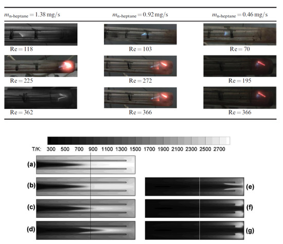
Figure 7.
Experimental and numerical study of diffusion combustion in a micro channel using liquid n-heptane and air mixture, with and without heat recirculation, by Li et al. [17]. Top: Photos of flame at different Reynolds numbers (b); Bottom: Temperature contours for various heat loss coefficients: (h Unit: W/m): (a) , (b) , (c) , (d) , (e) , (f) , (g) .
Xu et al. also studied a liquid fuel (ethanol) by performing experimental and numerical investigations of laminar flow with diffusion combustion in micro scale ceramic tubes of different inner diameters [18]. They employed numerical methods to capture micro flame characteristics as a way around the limitation of measurement tools in experiments. They designed several tests by varying the numerical conditions to examine the model capacity for predicting the micro flame characteristic correctly. As presented in Figure 8, Xu’s group confirmed that the liquid droplet radiation heat transfer and boundary slip had significant impacts on the results and should not be overlooked in modeling. The numerical simulations were obtained by solving the typical governing equations of mass conservation, momentum, energy, and species conservation. In these equations, the following physical phenomena are taken into account: multi-component diffusion, wall heat diffusion, radiation between the ceramic tube and combustion gasses, and evaporation to simulate droplets combustion process. Comparisons between numerical and experimental results such as height and width of the flames and maximal temperature showed that the discrepancies become maximum if the liquid droplet radiation heat transfer is not taken into account. Consistent with the findings by Nakamura et al. [10], the flame height and width increased almost linearly with the volume flow rate of the fuel, but the gradient increases as the tube inner diameter decreases. In addition, the maximal temperature increases first and then decreases after a certain flow rate.
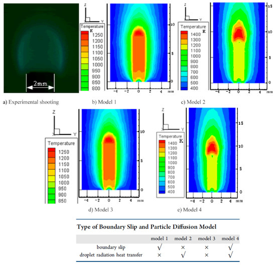
Figure 8.
Experimental and numerical study of a liquid ethanol micro-combustion in ceramic tubes with different inner diameters by Xu et al. [18]. Flame characteristics for tube 1 at flow rate of 1.8 mL/h.
Following the previous procedure, Xu et al. investigated the diffusion combustion characteristics of liquid bio-butanol at micro scales under an electric field [19]. The electric field was imposed to analyze its impact on the flame structure and investigate the quenching phenomenon, in order to improve the stability and efficiency of liquid fuel micro flames, which are known to become unstable and tend to extinguish easily. They observed that the electric field has significant impacts on the micro scale combustion (see Figure 9). Increasing the DC voltage, the quenching flow rate decreased initially and after reaching its trough value, it started to gradually increase. The flame height, however, showed an opposite behavior: increasing at first and then decreasing. Moreover, the flame reached its maximum height faster in the smaller tube. It was also observed that increasing the fuel flow rate results in an almost linear increase of the highest temperature of flame. In this work, the numerical results were in a good agreement with the experimental measurements. The maximum deviation observed in this work was for the flame height (). In the case of the maximal temperature, the deviations were less than . It is noted that the combustion process in this work was modeled by a simplified two-step reaction mechanism. It was however, one of the first studies to model the gasification process of a liquid fuel by calculating the heat change of the liquid droplets.
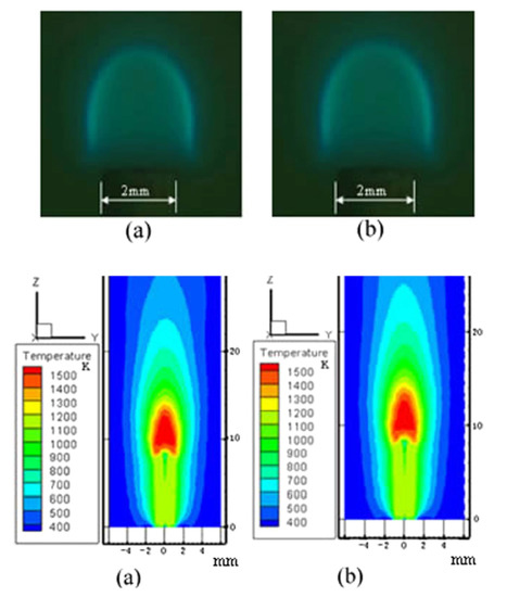
Figure 9.
Experimental and numerical study of the effects of electric field on micro-combustion using liquid biobutanol by Xu et al. [19]. Experimental micro flame structure (Top) and Flame temperature field of numerical simulation (Bottom), with the flow rate of 0.9 mL/h for tube 1. (a) 0 V; (b) 4000 V.
To understand the limits of spherical hydrogen diffusion flames, Lecoustre et al. performed a study of one-dimensional spherical laminar diffusion flames, using adiabatic porous burners of various diameters [20]. The combustion reaction was modelled with an emphasis on kinetics of extinction, using detailed chemical mechanism with 9 species and 28 reactions, and transport properties with updated light component diffusivities. They tested two configurations: (1) normal ( flowing into quiescent air) and (2) inverse (air flowing into quiescent ). The flames were simulated using a steady-state laminar flame code with detailed chemistry and transport, initially developed by Sandia National Laboratories for premixed flames [21], and modified to include diffusion flames. For equivalent heat release rates, the inverse flames showed to be smaller and hotter than normal flames. For example, at large flow rates, the peak temperature of inverse flames was 290 K higher than the adiabatic flame temperature of the normal flames, which is attributed to the low Lewis number of the ambient gas for inverse flames fueled by hydrogen. Similar to quenching limits measured in normal gravity on tube burners, the lower quenching limits of normal flames were predicted with a lower bound of 0.25 W, but in case of inverse flames the lower heat release rate increased to 1.38 W. The minimum temperatures at the quenching limits were 1070 K and 903 K for normal and inverse flames, respectively. Some of the aforementioned results are graphically presented in Figure 10.
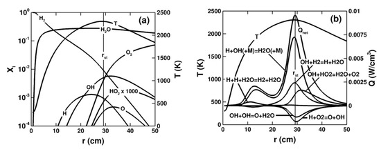
Figure 10.
Modeled quenching limits of hydrogen diffusion flames by Lecoustre et al. [20]. Flame structure (a) and local heat release rates (b) for a large H2/air normal flame on a 5 mm radius burner.
Hossain and Nakamura conducted a numerical investigation to study the thermal and chemical structures formed in the hydrogen-air jet flames in a micro burner, where the excess heat recirculation through the burner wall has the potential to stabilize the miniaturized jet diffusion flame [22]. In their numerical simulations, they considered an axis-symmetric 2D case, where different burner materials and fuel ejecting velocities were tested to understand their roles on the flame structure inside the combustion chamber. Figure 11 presents a sample of the results obtained from these simulations. The thermal structure of the micro-jet flame under different burner materials (titanium and aluminum) showed that the overall flame shape and height were almost identical. They however behaved differently near the burner port. Here, due to the low conductivity of the materials, the heat recirculation from the flame toward the burner is small and therefore the burner tip and its vicinity were continuously heated up. The incoming fuel was also preheated, which increased the maximum flame temperature slightly. Decreasing the fuel velocity resulted in pushing the stoichiometric mixture fraction towards the burner surface, i.e., the flame height decreased, which was also evident in the OH distribution. It is important to note that even at extremely low Reynolds numbers, the effective usage of the burner wall properties and heat transfer can stabilize a significantly small flame. They also showed that enriching the fuel mixture can modify the flame structure and expand the low stability limit.
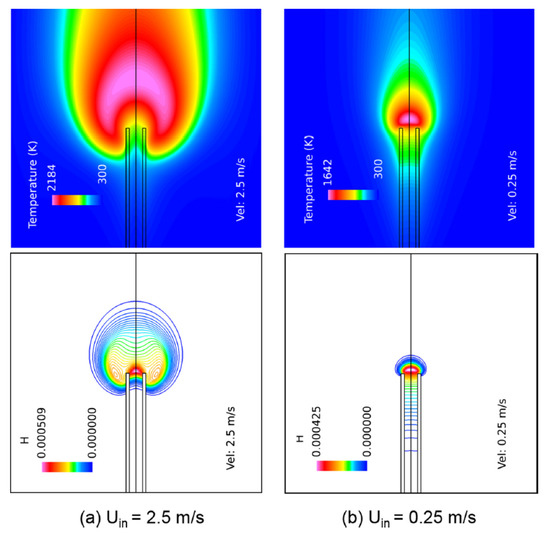
Figure 11.
Numerical study of hydrogen-air jet flames in a micro burner by Hossain and Nakamura [22]. 2D temperature and mass fraction of H-atom distributions for different fuel ejecting velocities ((a) m/s and (b) m/s) over titanium burner.
In order to investigate the wall thermal interactions with the flame, Zhang et al. conducted a numerical and experimental research to study the combustion characteristics of the non-premixed micro-jet hydrogen flame in an air co-flow, while considering the thermal interactions through the solid walls of the micro tube [23]. The experimental results showed how the flame height and shape, and correspondingly the OH-radical distributions would change with fuel flow velocity. Such results were well captured by the numerical simulations (see Figure 12). The evolution of the flame temperature field with the velocity variations was analyzed by post processing the numerical simulations results. Th flame temperature was shown to reach its maximum of 2300 K for the fuel flow velocity range of 5–25 m/s and to decrease smoothly in the fuel velocity range of 1–5 m/s. The fuel velocity could not go below 0.08 m/s, where the flame extinction occurred. The flame shape and structure were also found to behave differently at fuel flows with high, intermediate and low velocities. The impacts of thermal interactions between flames and the solid walls were different depending on the fuel velocity. For example, for higher fuel velocities, the external surface of the tube had a positive effect on the flame stability, while this effect was negative at lower velocities as the walls absorbed heat from the flame. Figure 12 compares these impacts for different fuel flow velocities. Numerical simulation methodology that was adopted in this work was similar to that of Hossain and Nakamura [22], with the addition of the heat interactions between the fluid and solid by coupling the boundary conditions.
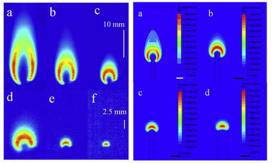
Figure 12.
Experimental and numerical study of the thermal interaction with solid micro tube in non-premixed hydrogen jet flames by Zhang et al. [23]. Left: OH-PLIF images of hydrogen micro-jet flames at different fuel flow velocities: (a) 10 m/s; (b) 5 m/s; (c) 2.5 m/s; (d) 1 m/s; (e) 0.35 m/s; (f) 0.17 m/s; Right: Computational OH mole fractions of hydrogen micro-jet flames at different fuel flow velocities: (a) 2.5 m/s; (b) 1 m/s; (c) 0.35 m/s; (d) 0.17 m/s.
Ayed et al. took advantage of the latest advances in numerical investigation of micro-combustion devices and conducted an interactive experimental and numerical study to optimize a micro-mix hydrogen combustion in a test burner and achieve minimum NOx emissions [24]. In this work, authors studied the implications of the turbulent flow field on the NOx emissions by applying different combustion models and characterizing the turbulent micro-mix flame structures. In order to reduce the NOx emissions, they used a cross-flow mixing of air and hydrogen, where gaseous hydrogen is injected perpendicularly into an air cross-flow and reacts in multiple miniaturized diffusion-type flames. The simulations were performed by the commercial CFD tool STAR-CCM+ [25]. In their numerical simulation approach, they used the k-epsilon turbulent model to predict the flow field. To characterize the hydrogen combustion process, they used and compared the following models: (1) EDM (Eddy Dissipation) model, (2) ED-FR (Eddy Dissipation–Finite Rate) model, and (3) EDC (Eddy Dissipation Concept) model. The calculation of reaction rates and species consumption/formation rates were obtained by implementing a detailed hydrogen reaction mechanism including 19 reversible reactions and 9 species. In the wall treatment of the RANS model, the local dimensionless wall distance, which depends on the wall distance, the friction velocity and the kinematic viscosity was utilized. The geometric model to perform the numerical simulations was derived from the burner configuration APU 030 ED 6.7 [26]. Comparisons between the findings from these three models and the experimental results illustrated qualitative agreement with the experimental findings (see Figure 13); however, the predictions from the EDC model that was closest to the measured values, had 21.5% error. In general, the numerical simulations were able to capture the micro-mix flame anchoring and structure for the operation parameters considered in this work. However, further investigations will be necessary to increase the precision of the numerical results involving diffusion flames, especially at micro scales.
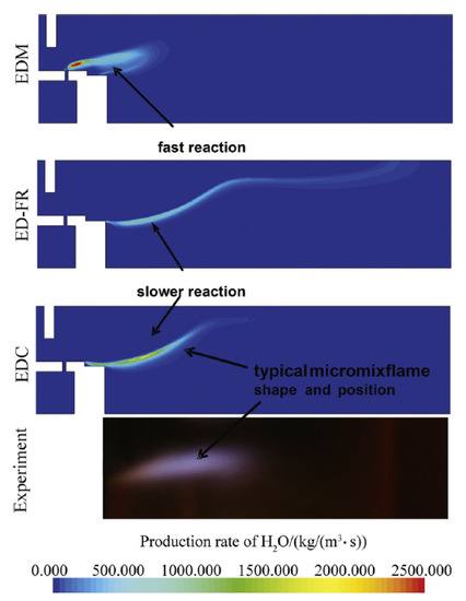
Figure 13.
Experimental and numerical study of the dry-low-NOx hydrogen micro-mix combustion chamber by Ayed et al. [24]. Calculated reaction rates in comparison with visual flame structure.
Most recently, Gao et al. investigated the combustion characteristics of micro-jet diffusion flames with a mixture of hydrogen and methane fuels and examined the stabilization mechanisms for different fuel mixture compositions [27]. They reported that flames with hydrogen as the base fuel would always attach to the burner, as opposed to flames with methane as the base fuel. Comparing the dominant intermediate-consumption steps in both methane and hydrogen, those of hydrogen flame were found to have significantly lower activation energies. In addition to the comparisons between hydrogen- and methane-based flames, the impacts of fuel mixing were studied as well, where the combustion characteristics of different fuel mixture ( + ) compositions were analyzed and compared (see Figure 14). They reported that the fraction of hydrogen in the fuel mixture has a controlling impact on the burner flame temperature, which was found to be attributed to the reaction rate of H + + M → + M as it is suppressed by reactions involving intermediate species such as and in methane consumption. With that, they suggested that the combination of methane and hydrogen can be considered a good alternative to prevent the potential thermal damages to the chamber.

Figure 14.
Numerical study of micro-jet hydrogen/methane diffusion flames by Gao et al. [27]. Top: Computed temperature contours and heat release rate (HRR) isopleths for flames at fuel jet velocity of m/s for (a) K (b) K, and for flames at m/s for (c) K (d) K; Bottom: Computed temperature contours and HRR isopleths at the thermal conductive burner condition (the thermal conductivity of burner wall is 16 W/m-K) for (a) flame at m/s, (b) / 80%/20% flame at 1.2 m/s, (c) / 20%/80% flame at m/s, (d) flame at m/s. Here the flame temperatures range between 2028 K and 2034 K.
Gao et al. continued their investigations by conducting a numerical study of micro-jet diffusion flames using different fuels for several operating conditions by varying the inlet jet velocities and burners proprieties. The objective of this study was to prove the importance of the heat-recirculation impact on the flame stabilization at near-extinction conditions [28]. They used different fuels such as hydrogen, methane and dimethyl ether (DME), and employed a chemical kinetics mechanism with 17 species and 58 reactions. The first part of the study consisted of the analysis of the heat recirculation, , and the heat losses through the burner surfaces, , by varying the thermal conductivities, , from 1 to 100 W/m-K, and the wall thicknesses, , from 0.2 to 0.8 mm. To evaluate the global thermal effect on the burner, an effective excess enthalpy was defined, , where M is the mass flow rate (kg/s). They reported that the ratio between and increases monotonically as the jet velocity increases. This results in a critical fuel velocity, where overcomes , i.e., the heat recirculation can shadow the impact of the heat losses. Correspondingly, as and decrease at near extinction conditions, the flame temperature increases, i.e., the extinction limit for a specific fuel jet velocity can be extended. Figure 15 (left) represents the effective excess enthalpy, H, and the maximum flame temperatures of a micro-jet methane combustion, for different burners, over fuel jet velocities ranging from 0.1 m/s to 3.2 m/s. It is evident that the heat-recirculation can assist the combustion regime for positive values of H. In second part of the work, simulations were performed for the same burner proprieties, = 6 W/(m-K) and = 0.2 mm, and using different fuels to analyze the impact of the effective excess enthalpy, H. Results of this analysis are presented in Figure 15 (right). The investiagotrs concluded that for fuels with Schmidt number (Sc) > 1.0, such as DME (Sc = 1.2), the flame is lifted, resulting in a negligible flame–burner interaction (H ≈ 0). Such behavior was the opposite for fuels with Sc < 1.0, such as methane (Sc = 0.7) and hydrogen (Sc = 0.2), where the chemical kinetics is dominant in the flame base structure, and higher values of H are expected.
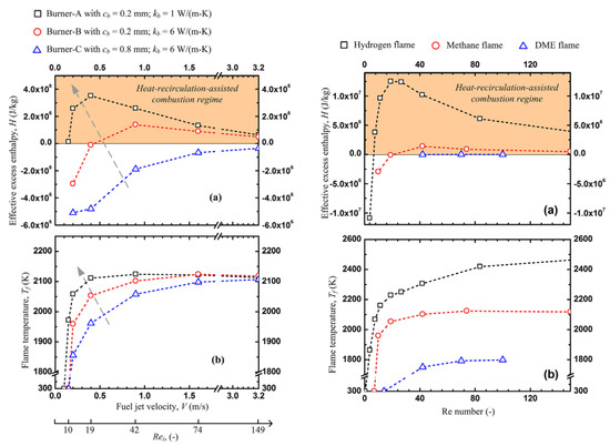
Figure 15.
Numerical study on heat-recirculation assisted combustion for small scale jet diffusion flames at near-extinction condition by Gao et al. [28]. Left: Effective excess-enthalpies (a) and flame temperatures (b) over fuel jet velocities range from the extinction limits to 3.2 m/s for different burners: Burner-A with = 0.2 mm and = 1 W/(m-K), Burner-B with = 0.2 mm and = 6 W/(m-K) and Burner-C with = 0.8 mm and = 6 W/(m-K); Right: Effective excess-enthalpies (a) and flame temperatures (b) as a function of Re number for , , and DME flames. The burner wall thickness is and the thermal conductivity is = 0.2 mm and = 6 W/(m-K).
Li et al. investigated the mixing performance and the diffusion combustion characteristics in a 2D planar micro-combustor using hydrogen and air separated by a plate [7]. This study was conducted through numerical simulations and consisted of various boundary conditions and burner geometries. Analyzing the mixing performance, flame stability limits and the combustion efficiency, they confirmed that the separating plate improved the mixing performance for lower inlet velocities and channel heights (see Figure 16 (left)), which is attributed to the extended residence time and shortened diffusion distance. They also reported that due to the improved mixing process, the combustion efficiency increased by reducing the combustor height, for the same inlet air velocities (see Figure 16 (right)).
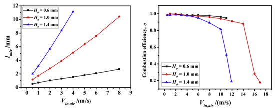
Figure 16.
Numerical investigation on mixing performance and diffusion combustion characteristics of and air in planar micro-combustor by Li et al. [7]. (Left): Required mixing distance versus inlet air velocity for micro-combustors with different heights; (Right): Variations in combustion efficiency versus inlet air velocity in three micro-combustors with different heights.
In a most recent paper on this topic, Kang et al. [29] conducted a numerical study to reproduce the “flame-street” phenomenon described in the experimental work of Miesse et al. [30]. The “flame-street” is a phenomenon observed in diffusion flames, and is used to describe a separated flame into a discrete series of flame segments. Typically “flame-street” phenomenon has been reported in experimental studies, but this work by Kang et al. seeks to understand its characteristics with the help of numerical simulations. Using a reacting flow solver on the open-source software OpenFOAM [31], and with a chemical reaction mechanism of 21 species and 84 reactions, they simulated a 3D geometry channel with 30 mm in length, 5 mm in width and 0.75 mm in height. They used methane and oxygen as fuel and oxidizer, with inlet flow rates of 100 sccm and 200 sccm, respectively. To consider the heat external losses through the wall, a conjugate heat transfer model was considered, with wall material proprieties identical to the experimental work. The flame-street behavior consisting of a bibrachial, presented a long diffusion tail, a weaker fuel-lean premixed branch, and consecutive downstream “new moon”-like flamelets each with a fuel-lean and a fuel-rich premixed branch (see Figure 17 (left)), where is the fuel mass fraction for an unburnt fuel/oxidizer mixture at stoichiometric conditions. Also, the effects of wall thermal conditions and species mass diffusion on the formation of the flame-street were analyzed, and verified that the flame-street structure was formed at a moderate wall heat loss range, between 800–1100 K wall temperatures (see Figure 17 (right)).
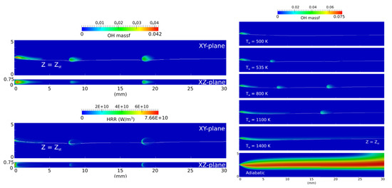
Figure 17.
Numerical investigation on the thermo-chemical structures of methane-oxygen diffusion flame-streets in a microchannel by Kang et al. [29]. (Left): Contours of OH mass fractions and heat release rate (HRR) on the sliced XY- and XZ-plane along the channel centerline; (Right): Effects of wall thermal conditions on flame behaviors.
4. Conclusions
The increasing attentions to the combustion-based micro power generation systems, mainly due to the high energy density of hydrocarbon fuels, has persuaded researchers to expand their efforts to investigate the combustion characteristics at micro scales and seek ways to achieve stabilized combustion and optimize the power generation process in such devices. This work summarized the pertinent investigations revolved around non-premixed (diffusion) combustion regime, which is most commonly employed in practical systems. With the complexities and expenses associated to the experimental analyses, the application of numerical simulations to model combustion at micro scales, especially diffusion flames which are the focus of this work, has been widely considered and shown to provide promising insights. The review in this paper confirmed the strength of the numerical simulations, to both qualitatively and quantitatively predict the flame behavior if used properly. Using different numerical approaches over the past couple of decades, diffusion combustion at micro scale has been extensively studied and characterized. Such case are found to be very sensitive to the operating conditions, i.e., the flame characteristics, stability conditions, and flammability limits can be altered by varying different parameters or the system configuration. For example, conjugate heat transfer or heat recirculation were found to have strong impacts on the flammability limit. Various studies showed that changing the fuel type, fuel/air composition, inlet velocity, burner geometry or material, etc. can change the flame characteristics such flame location, flame height, flame temperature and flame stability considerably. This review of the studies on the numerical investigations and approaches in diffusion combustion characteristics at micro scales presents a pathway for researchers in this field to more efficiently move forward with their research.
Author Contributions
Conceptualization, P.R.R., M.A. and A.M.A.; methodology, P.R.R., M.A. and A.M.A.; investigation, P.R.R., M.A. and A.M.A.; writing—original draft preparation, P.R.R.; writing—review and editing, P.R.R., M.A. and A.M.A.; funding acquisition, P.R.R., M.A. and A.M.A.
Funding
This research received external funding by FAPESP through Project No. 2015/26842-3. A.M. Afonso acknowledges the funding by FCT under Project No. PTDC/EMS-ENE/3362/2014.
Acknowledgments
P. R. Resende acknowledges the funding by FAPESP through Project No. 2015/26842-3. A.M. Afonso acknowledges the funding by FCT under Project No. PTDC/EMS-ENE/3362/2014. M. Ayoobi acknowledges the support from Wayne State University for this publication.
Conflicts of Interest
The authors declare no conflict of interest.
References
- Ju, Y.; Maruta, K. Microscale combustion: Technology development and fundamental research. Prog. Energy Combust. Sci. 2011, 37, 669–715. [Google Scholar] [CrossRef]
- Nakamura, Y.; Gao, J.; Matsuoka, T. Progress in small-scale combustion. J. Therm. Sci. Technol. 2017, 12, JTST0001. [Google Scholar] [CrossRef][Green Version]
- Norton, D.G.; Vlachos, D.G. Combustion characteristics and flame stability at the microscale: A CFD study of premixed methane/air mixtures. Chem. Eng. Sci. 2003, 58, 4871–4882. [Google Scholar] [CrossRef]
- Ayoobi, M.; Schoegl, I. Numerical analysis of flame instabilities in narrow channels: Laminar premixed methane/air combustion. Int. J. Spray Combust. Dyn. 2017, 9, 155–171. [Google Scholar] [CrossRef]
- Cova, A.; Resende, P.R.; Cuoci, A.; Ayoobi, M.; Afonso, A.M.; Pinho, C.T. Numerical Studies of Premixed and Diffusion Meso/Micro-Scale Flames. Energy Procedia 2017, 120, 673–680. [Google Scholar] [CrossRef]
- Resende, P.R.; Afonso, A.; Pinho, C.; Ayoobi, M. Impacts of Dilution on Hydrogen Combustion Characteristics and NOx Emissions. J. Heat Transf. 2018, 141, 012003. [Google Scholar] [CrossRef]
- Li, L.; Yuan, Z.; Xiang, Y.; Fan, A. Numerical investigation on mixing performance and diffusion combustion characteristics of H2 and air in planar micro-combustor. Int. J. Hydrog. Energy 2018, 43, 12491–12498. [Google Scholar] [CrossRef]
- Cheng, T.S.; Wu, C.Y.; Chen, C.P.; Li, Y.H.; Chao, Y.C.; Yuan, T.; Leu, T.S. Detailed measurement and assessment of laminar hydrogen jet diffusion flames. Combust. Flame 2006, 146, 268–282. [Google Scholar] [CrossRef]
- Cuoci, A.; Frassoldati, A.; Faravelli, T.; Ranzi, E. A computational tool for the detailed kinetic modeling of laminar flames: Application to C2H4/CH4 coflow flames. Combust. Flame 2013, 160, 870–886. [Google Scholar] [CrossRef]
- Nakamura, Y.; Ban, H.; Saito, K.; Takeno, T. Structures of Micro (Millimeter Size) Diffusion Flames. In Proceedings of the Third International Symposium on Scale Modeling, Nagoya, Japan, 10–13 September 2000; Volume ISSM3-E7. [Google Scholar]
- Nakamura, Y.; Yamashita, H.; Saito, K. A numerical study on extinction behaviour of laminar micro-diffusion flames. Combust. Theory Model. 2006, 10, 927–938. [Google Scholar] [CrossRef]
- Cheng, T.S.; Chao, Y.C.; Wu, C.Y.; Li, Y.H.; Nakamura, Y.; Lee, K.Y.; Yuan, T.; Leu, T.S. Experimental and numerical investigation of microscale hydrogen diffusion flames. Proc. Combust. Inst. 2005, 30, 2489–2497. [Google Scholar] [CrossRef]
- Chen, C.P.; Chao, Y.C.; Cheng, T.S.; Chen, G.B.; Wu, C.Y. Structure and stabilization mechanism of a microjet methane diffusion flame near extinction. Proc. Combust. Inst. 2007, 31, 3301–3308. [Google Scholar] [CrossRef]
- CFD-ACE+. 2018. Available online: https://www.esi-group.com/software-solutions/virtual-environment/cfd-multiphysics/ace-suite/cfd-ace (accessed on 20 June 2019).
- Badra, J.; Masri, A. Design of a numerical micro-combustor for diffusion flames. In Proceedings of the Seventh Mediterranean Combustion Symposium (MCS-7), Sardinia, Italy, 11–15 September 2011. [Google Scholar]
- ANSYS-Fluent. 2018. Available online: https://www.ansys.com/products/fluids/ansys-fluent (accessed on 20 June 2019).
- Li, J.; Huang, J.; Zhao, D.; Zhao, J.; Yan, M.; Wang, N. Diffusion combustion of liquid heptane in a small tube with and without heat recirculating. Combust. Sci. Technol. 2012, 184, 1591–1607. [Google Scholar] [CrossRef]
- Xu, T.; Gao, X.N.; Yang, J.; Gan, Y.H.; Yang, Z.L.; Zhang, Z.G. Experimental and Numerical Simulation Study of the Microscale Laminar Flow Diffusion Combustion of Liquid Ethanol. Ind. Eng. Chem. Res. 2013, 52, 8021–8027. [Google Scholar] [CrossRef]
- Xu, T.; Chen, Q.; Zhang, B.; Lu, S.; Mo, D.; Zhang, Z.; Gao, X. Effects of electric field on microscale flame properties of biobutanol fuel. Sci. Rep. 2016, 6, 32938. [Google Scholar] [CrossRef] [PubMed]
- Lecoustre, V.R.; Sunderland, P.B.; Chao, B.H.; Axelbaum, R.L. Modeled quenching limits of spherical hydrogen diffusion flames. Proc. Combust. Inst. 2013, 34, 887–894. [Google Scholar] [CrossRef]
- Kee, R.J.; Grcar, J.F.; Smooke, M.D.; Miller, J.A.; Meeks, E. Premix: A FORTRAN Program for Modeling Steady Laminar One-Dimensional Premixed Flames; Technical Report No. SAND85-8240; Sandia National Laboratories: Albuquerque, NM, USA, 1987. [Google Scholar]
- Hossain, A.; Nakamura, Y. Thermal and chemical structures formed in the micro burner of miniaturized hydrogen-air jet flames. Proc. Combust. Inst. 2015, 35, 3413–3420. [Google Scholar] [CrossRef]
- Zhang, J.; Li, X.; Yang, H.; Jiang, L.; Wang, X.; Zhao, D. Study on the combustion characteristics of non-premixed hydrogen micro-jet flame and the thermal interaction with solid micro tube. Int. J. Hydrogen Energy 2017, 42, 3853–3862. [Google Scholar] [CrossRef]
- Ayed, A.H.; Kusterer, K.; Funke, H.H.W.; Keinz, J.; Striegan, C.; Bohn, D. Experimental and numerical investigations of the dry-low-NOx hydrogen micromix combustion chamber of an industrial gas turbine. Propuls. Power Res. 2015, 4, 123–131. [Google Scholar] [CrossRef]
- STAR-CCM+. 2018. Available online: https://mdx.plm.automation.siemens.com/star-ccm-plus (accessed on 20 June 2019).
- Funke, H.; Recker, E.; Börner, S.; Bosschaerts, W. LES of jets-in-cross-flow and application to the micromix hydrogen combustion. In Proceedings of the 19th International Symposium on Air Breathing Engine, Montreal, QC, Canada, 7–11 September 2009; American Institute of Aeronautics and Astronautics: Montreal, QC, Canada, 2009. [Google Scholar]
- Gao, J.; Hossain, A.; Nakamura, Y. Flame base structures of micro-jet hydrogen/methane diffusion flames. Proc. Combust. Inst. 2017, 36, 4209–4216. [Google Scholar] [CrossRef]
- Gao, J.; Hossain, A.; Matsuoka, T.; Nakamura, Y. A numerical study on heat-recirculation assisted combustion for small scale jet diffusion flames at near-extinction condition. Combust. Flame 2017, 178, 182–194. [Google Scholar] [CrossRef]
- Kang, X.; Sun, B.; Wang, J.; Wang, Y. A numerical investigation on the thermo-chemical structures of methane-oxygen diffusion flame-streets in a microchannel. Combust. Flame 2019, 206, 266–281. [Google Scholar] [CrossRef]
- Miesse, C.; Masel, R.; Short, M.; Shannon, M. Experimental observations of methane–oxygen diffusion flame structure in a sub-millimetre microburner. Combust. Theory Model. 2005, 9, 77–92. [Google Scholar] [CrossRef]
- OpenFoam. 2019. Available online: https://www.openfoam.com (accessed on 20 June 2019).
© 2019 by the authors. Licensee MDPI, Basel, Switzerland. This article is an open access article distributed under the terms and conditions of the Creative Commons Attribution (CC BY) license (http://creativecommons.org/licenses/by/4.0/).