Abstract
The dimension detection of high-speed railway track slabs is one of the most important tasks before the track slabs delivery. Based on the characteristics of a 3D scanner which can acquire a large amount of measurement data continuously and rapidly in a short time, this paper uses the integration of 3D scanner and the intelligent robot to detect the China Railway Track System (CRTSIII) track slab supporting block plane, then the dense and accurate supporting block plane point cloud data is obtained, and the point cloud data is registered with the established model. An improved Random Sample Consensus (RANSAC) plane fitting algorithm is also proposed to extract the data of supporting block plane point cloud in this paper. The detection method is verified and the quality analysis of the detection results is assessed by a lot of real point cloud data obtained on site. The results show that the method can meet the quality control of CRTSIII finished track slab and the detection standard. Compared with the traditional detection methods, the detection method proposed in this paper can complete the detection of a track slab in 7 min, which greatly improves the detection efficiency, and has better reliability. The method has wide application prospects in the field of railway component detection.
1. Introduction
With the rapid development of Chinese high-speed railway construction and the continuous expansion of the international market, the demand for China Railway Track System (CRTSIII) track slabs with completely independent intellectual property rights continues to grow rapidly. The dimensional accuracy directly affects the stability, smoothness of the track and the safety of the train operation. Therefore, it is necessary to carry out a strict inspection on the external dimensions of the track slab before the delivery, and the higher requirements should also be put forward for the detection efficiency and detection accuracy of the track slab. At present, the detection of the deviation of the track slab external dimensions is mainly based on the manual inspection and contact-type measurement devices. It takes 40 min to detect a track slab, and the detection efficiency and repeatability of which are rather low, which cannot bring greater benefits to actual production [1].
With the advancement of computer science and information technology, the rapid development of industrial photography and machine vision, 3D scanning technology has become a widely used measurement technology with its fast scanning speed, non-contact, and high measurement accuracy [2,3,4,5]. Compared with other non-contact measurement methods [6,7,8,9], 3D scanning technology has the advantages of convenient integration with the computer, real-time processing and high flexibility of 3D reconstruction. It is widely applied in various fields, especially in industrial measurement, and it has great prospects. The data acquired by the 3D scanning system is point cloud data with three-dimensional information, which are usually defined by X, Y, and Z coordinates, and are often used to represent the external surface information of the object being scanned. In the last decade, capture technologies that can generate 3D point cloud data are becoming mature and usable for more accurate point cloud data acquisition. As point cloud data acquisition technology is gradually maturing, the demand for 3D scanning technology in workpiece positioning and inspection, vehicle detection, and aircraft and shipbuilding manufacturing in industrial measurement is also increasing. Yang [10] reported an automatic welding robot path planning system based on 3D vision technology and the successfully applied 3D scanning technology to the measurement and welding of complex geometric workpieces. Ahmed et al. [11] studied an edge and corner detection method for unstructured 3D point clouds for unorganized point clouds and its application in robot welding. Kim and Cheng et al. [12] presented a systematic and practical approach for dimensional and surface quality assessment of precast concrete elements using building information modeling (BIM) and 3D laser scanning technology, and the approach has the potential to produce an automated and reliable dimensional and surface quality assessment for precast concrete elements. Song et al. [13] investigated a new solution to the high-quality 3D reverse modeling problem of complex surfaces for fine workpieces by using a laser line-scanning sensor. The surface of the measured object was reconstructed completely and accurately, and the measurement accuracy of the workpiece reconstruction was relatively high. Simler and Berndt [14] used a 3D scanner to detect the surface of the car and proposed a new algorithm for various defects in the context of industrial surface inspection of free-form metallic pieces of cars. Jovancevic and Pham et al. [15] used three-dimensional scanning technology to automatically detect defects on the airplane exterior surface, and the result shows that their work is robust, effective, and promising for industrial applications. Reyno and Marsden et al. [16] also used 3D scanning technology to measure and evaluate surface damage of honeycomb sandwich panels, and the results showed that this method is more efficient and reliable compared to manual methods. According to the geometry of large-scale conical workpieces, integrating three-dimensional laser scanning and virtual environments, a novel rapid on-machine geometric measurement system was presented, and the 3D scanner is used to obtain the critical contour of the workpiece surface at high speed [17]. Javier and Jose et al. [18] discussed different non-contact 3D measuring strategies and presented a model for measuring geometrically complex parts, manipulated through a robot arm, using a novel vision system which consists a laser triangulation sensor and a motorized linear stage.
However, the application of 3D scanners for large-scale workpiece inspection, such as high-speed railway track slabs, is relatively rare. With an increasing amount of research—by institutes, units, and scholars—on high-precision track slab detection technology, many important theoretical achievements and patents have been attained. Lu et al. [1] investigated a photogrammetric method to detect the track slab. The method adopts the marking point and the base station ruler on the track slab. It uses a digital camera to take a picture, and then uses the image matching principle to realize the registration between the image pairs and extracts the three-dimensional coordinates of each key position to calculate each detection indicators. The method requires the inspection tooling to perform the matching measurement, which can meet the requirements of rapid measurement on site. Fan et al. [19] introduced the concept of industrial digital photogrammetry in the detection of CRTS III track slab. The system is used as follows the track slab is laid flat, the code control bracket is placed on the track slab to be detected, and the measuring device is erected thereon, so that the laser points of the guiding device are all projected onto the key position of the supporting block, and controlled. The camera motion completes the data acquisition of the whole slab, and finally extracts all the detection indicators by using feature extraction and calculation methods based on image features. Xue et al. [20] reported a linear detection system for the track slab rapid detection system based on the three-dimensional detection technology of line image technology. The high-precision measurement reference platform and fast-moving mechanism are used to realize the plane image and 3D model size extraction of the track slab, and the key geometry of the track slab is obtained by algorithm correction. Xu et al. [21] investigated a CRTS III track slab detection method based on laser tracking and handheld laser scanning combination. The method uses a hand-held laser scanner to scan the track slab in all directions, and the laser tracker achieves the real-time position and posture of the scanner to complete the stitching of the point cloud data. In this cycle, the point cloud data acquisition of the entire track slab surface is completed. Finally, the point cloud classification algorithm is used to classify different feature planes, thereby extracting the detection indexes of the track slab. When this detection method is used to detect the relative dimensional deviation of the track slab embedded bushing, it needs to rely on the spherical self-centralizing tooling, so the automatic detection cannot be completely realized. When the detection method detects the dimensional deviation of the pre-embedded casing of the track slab, it is necessary to use the spherical self-centering tooling, and the automatic detection cannot be fully realized. Yang et al. [22] discussed the application of 3D laser scanning technology in the detection of CRTS III track slab. A large amount of point cloud data on the track slab surface is used for 3D reconstruction of the target, and the target geometric data is quickly obtained by the reconstructed model library. Finally, the target geometric data is compared with the BIM model to determine the construction deviation accurately.
Track slab detection methods based on three-dimensional scanners, photogrammetry, and other technologies are constantly being proposed. Such detection methods considerably improve detection efficiency while ensuring detection accuracy. The detection time of one slab can be controlled within 15 min, and the efficiency is improved by 60% compared with the traditional contact detection. The track slab detection technology has a qualitative leap, but there are some limitations of the current methods. To overcome these limitations of the current methods, this study uses 3D scanning technology combined with intelligent robot to obtain 3D point cloud data of the track slab detection index area and achieves the rapid detection of CRTSIII track slab. An improved RANSAC method is presented to extract the point cloud of the supporting block plane.
In this paper, we collected the data in the operation site by the system which includes the 3D scanner and the intelligent robot. Then, the obtained point cloud data was denoised, spliced, registered, and the surface of the supporting block plane was extracted. A lot of experimental work was done, and the detection results of the supporting block plane were analyzed and evaluated. Our final findings provide theoretical support for track slab detection and improve work efficiency in the field of track slab detection.
2. 3D Measurement Point Cloud Acquisition and Preprocessing
2.1. 3D Scanning Measurement Process
Figure 1a shows the overall architecture of the entire detection system. The high-repetition and high-stability intelligent robot carries a 3D scanner to automatically acquire high-precision point cloud data on the surface of the CRTSIII track slab. As shown in Figure 1b, the robot carries the 3D scanner to detect the track slab supporting block according to the preset path. When the light beam emitted by the light source is irradiated onto the object to be measured, the surface contour information of the measured object can be obtained, and three-dimensional point cloud information is generated.
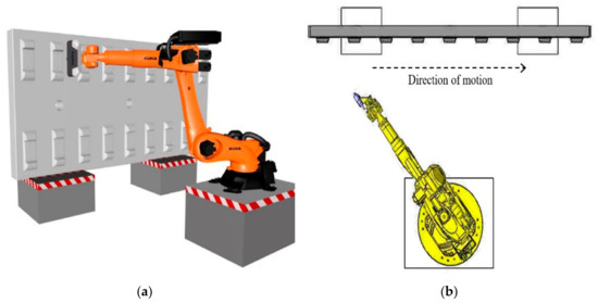
Figure 1.
Overall design and operation of the detection system: (a) The detection system overall architecture; (b) The system moving direction.
2.2. Track Slab Solid Model and Feature Establishment
The obtained single supporting block point cloud data contains many inspection indicators, such as supporting block plane, pre-embedded casing, single rail vise spacing (small jaw distance), etc. This paper will mainly discuss supporting block plane detection method.
The core inspection index of the supporting block plane as the track slab inspection is the key to the quality control of the track slab dimensions. Before the extraction of the supporting block plane point cloud data, the physical modeling of the track slab is carried out firstly, and the basic geometric features are established. Secondly, the point cloud data is denoised and spliced. Finally, the point cloud data is registered with the design model. The segmentation of point cloud data is the basis of point cloud computing and it plays a crucial role in subsequent plane extraction. Point cloud data segmentation methods can be broadly classified into model-driven and data-driven [23]. This paper will adopt the model-driven method, which is a top-down method. The model-driven method works as follows: The feature library is built firstly, and then the point cloud is matched with the predefined features to obtain the feature-based point cloud segmentation results. Model-based segmentation can find several rules for segmentation regions, helping data simplification, and thus speeding up data reconstruction and object recognition [24].
The basic unit of the part model is the feature, and the establishment of features is based on the sketch. The model of the supporting block and the track bottom slab part is respectively established, and the complete track slab is further assembled to complete the construction of the track slab model.
The parameters of the track slab model are obtained through the design drawing and point cloud reverse engineering. The design includes the parameters such as the length, width, thickness, and fastener spacing of each type of track slab. The 3D model is drawn according to the geometric relationship of the design parameters and the basic geometric features are established. The modeling process is shown in Figure 2.
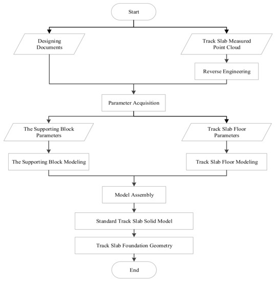
Figure 2.
Track slab solid modeling process.
The model and geometric features are established to semantically segment the acquired original point cloud data, and the original point cloud data is divided into the supporting block, the jaw surface, and the embedded circle according to the established geometric feature information.
2.3. Point Cloud Data Preprocessing
2.3.1. Point Cloud Denoising
In the process of obtaining massive 3D point cloud data, other redundant points or noise points will inevitably be obtained. These noises not only increase the volume of point cloud data, but also affect the precision of point clouds fitting and registration [25], so they must be removed.
At present, there are two main methods for dealing with noise, manual denoising and automatic denoising [26,27]. For automatic denoising of point clouds, algorithms such as least squares filtering (for ordered point clouds), median filtering (for ordered point clouds), and bilateral filtering algorithms (for cluttered point clouds) are commonly used [28,29]. Manual denoising means that for some isolated points and redundant points, these points can be manually removed. Due to the advanced production process of the track slab, the surface of the track slab is smooth and flat, and the measured track slab point cloud data quality is better, and the noise points are mostly isolated points and redundant points, which can be directly denoised manually.
2.3.2. Point Cloud Splicing
The original point cloud data of the surface of the supporting block obtained by the three-dimensional scanner is located at the scanner coordinate system, and the origin of the coordinate system is the phase center of the scanner. The point cloud data is overlapped in the scanner coordinate system, which is inconsistent with the actual supporting block position, as shown in Figure 3. In order to achieve the registration of the point cloud and the standard track slab model, it is necessary to first splice the point cloud of each supporting block to restore the true position of the point cloud.
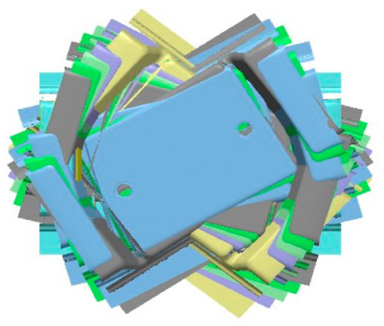
Figure 3.
Overlapping scattered original point cloud data.
Considering the field of view of the 3D scanner, the placement of the track slab, the processing time of the point cloud data and the efficiency of the system detection, we use the direct conversion method of the coordinate system to realize the splicing of each part of the point clouds, as shown in Figure 4. The detailed process is as follows:
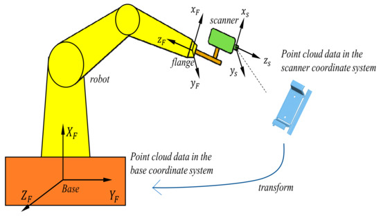
Figure 4.
Schematic diagram of point cloud splicing.
Step 1: The robot carries the 3D scanner to move to the specified position to obtain the point cloud data of the corresponding area, and obtains the current position and posture parameters of the camera-type 3D scanner coordinate system (TOOL) in the base coordinate system, including three rotation parameters (εX, εY, εZ) and three translation parameters (ΔX, ΔY, ΔZ) and a proportional parameter [30,31] which are shown in Figure 5.
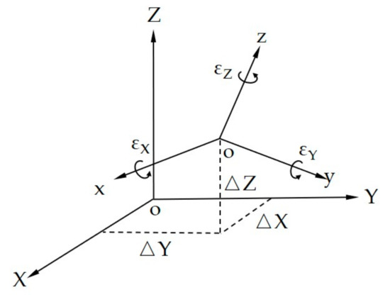
Figure 5.
BASE and TOOL space rectangular coordinate system.
Step 2: According to the position and attitude parameters of the transmitted flange (FLANGE), the conversion matrix (rotation matrix Rt and translation matrix Tt) between the two coordinate systems (photographed 3D scanner coordinate system and robot base coordinate system) is calculated.
First, the origin of the coordinate system is coincident by the translation of the coordinate origin, and then the rotation between the coordinate axes is realized by the rotation around the coordinate axis. Among them, the rotation matrix around the X, Y, and Z axes are
The rotation matrix is
The translation matrix is
Step 3: Converting the point cloud data of the part to the robot base coordinate system by using the transformation matrix;
Theoretically, the spatial scale between the scanner coordinate system and the robot coordinate system is consistent, there is no scaling, therefore, the scaling factor λ = 1 in this paper
Step 4: Obtaining the point clouds of all the features of the track slab, and repeating the above steps to complete the point cloud data splicing.
2.4. Point Cloud Data Registration
The track slab detection method in this paper adopts the idea that the point cloud data is automatically registered with the standard model [32,33,34] to improve the efficiency and automation of the track slab detection. Computer Aided Verification (CAV), a computer-aided verification method, is used to achieve automatic registration of point cloud data and standard models according to detection requirements. However, the premise of automatic registration is that the point cloud data is roughly similar to the standard model. Therefore, the initial registration of the point cloud data is required to move the point cloud data to the approximate position, and the ICP (iterative closest point)-based method is used to further iteratively calculate the point clouds and accurate registration of the model [35].
3. Supporting Block Plane Extraction
After completing the registration of the point cloud data and the standard track slab design model, the measured values of the characteristics of each detection index are calculated. Based on the geometric size (measured value) of each detected feature of the extracted track slab and the standard size (nominal value) of the standard design model, the deviation values of the two are calculated. The basis for extracting the parameters of each detection index is to fit the point cloud of the geometric parameter. In order to extract the slope of the supporting block, the angle between the supporting block plane and the jaw plane, the features of the height of the convexity and the skew, and the supporting block plane should be extracted first. Therefore, the plane fitting of the point cloud data of the supporting block plane should be carried out first.
In this paper, the point cloud plane fitting of the supporting block plane is an important part of the point cloud data processing and information extraction process, and it is the basis for the outer dimensions of the track slab. At present, the commonly used point cloud fitting algorithms are least squares method, eigenvalue method, global least squares method, RANSAC algorithm, etc. [36,37,38,39].
3.1. Improved RANSAC Plane Fitting Algorithm
Among many point cloud fitting algorithms, the RANSAC algorithm is widely used. Its robustness to noise and outliers makes RANSAC a suitable choice for performing shape detection on real-world scan data. Buer et al. [40] successfully used RANSAC to extract the main surface from a very dense 3D point cloud. Schnabel et al. [41] used the advantageous properties of the RANSAC algorithm to fit planes, cylinders, spheres, and torus in point clouds. Tarsha-kurdi et al. [42] successfully extracted the roof plane of the building automatically from the airborne laser data based on the RANSAC algorithm. All the research results show that the algorithm has a good effect on the plane fitting. RANSAC judgement criterion are as follows:
According to the basic criteria of the RANSAC algorithm, at least one set of sampling result points in the K group sampling under the confidence probability P is all valid points (inliers) [43].
Among them:
ε is the sample contamination rate (roughness ratio); n is the minimum number of points required to determine the parameters of model M; P is the probability of successful confidence; (1 − ε) is the probability of extracting a point as the correct point; indicates the probability of extracting all n points as correct points, and extracts n points to determine the model parameters; means that, under the condition that the above formula is satisfied, the probability that the K group samples are all correct points is P.
However, some improvements and corrections are required in order to make the algorithm more efficient for extracting the supporting block point clouds captured by the scanner. Therefore, compared with the basic method, we propose an improved RANSAC algorithm to improve the accuracy of extraction and the processing efficiency.
When the RANSAC algorithm performs plane fitting, its plane parameters are only fitted by three initial points (it takes at least three points to determine a plane). The plane fitting error of these three points may affect the fitting error judgment of all subsequent points. The farther away from the center of gravity of the three points, the larger the influence. Therefore, when the final optimal model (Best_Model_final) is selected, it is more reasonable to use the principle of least fitting error as the optimal model judgment criterion [36,44,45,46].
In order to avoid the cumulative effect of the error caused by using only three points to judge plane parameters, this paper improves the conventional RANSAC algorithm. After the RANSAC iteration is completed, the plane point sets obtained by RANSAC are re-fitted with the least squares to fit the plane parameters, and finally, the best fitting plane parameters of each plane are obtained. Take the fitting of a plane as an example:
- The RANSAC algorithm is used to select the optimal plane. The selection condition is that the minimum plane of the plane fitting error is used, and the minimum plane of the model fitting error is taken as the optimal fitting plane to obtain the model “Candidate_Best_Model”.
- Based on the point of the model “Candidate_Best_Model”, the least squares fitting method is used to solve the plane parameters of “Best_Model_Temporary”, and the “Best_Model_Temporary” temporary optimal plane parameters are obtained.
- Based on the parameters, all points in the point clouds are re-selected and judged instead of using the random sampling method. According to the rejection threshold t, all the points in the point clouds whose error with the “Best_Model_Temporary” is less than the threshold t are included in the plane, and together with the point clouds in n, the previous model constitute the new “Best_Model_Temporary” model;
- Repeat steps 2 and 3 above to end. Each time an iteration is completed, the temporary best model will be recorded. Repeat the iteration to get the final best plane “Best_Model_Final”. The determination condition of the end of the iteration is that the total number of interior points reaches a certain threshold. The threshold value should be determined according to the overall situation of the point clouds. In this paper, the fitting object is the point cloud data of the outer surface of the track slab supporting block. The overall flatness is smooth and the noise is less. Therefore, the threshold can be set to 90% of the total number of point clouds.
3.2. Algorithm Implementation
According to the above analysis and algorithm optimization, the improved RANSAC algorithm is used to planarly fit the point cloud data of the supporting block. The algorithm sets the sample contamination rate, the rejection threshold t, the minimum number of points to determine the parameters of a plane model n = 3, and the minimum number of points N in a single plane according to the point cloud density, the scanning quality, and the roughness of the outer surface of the supporting block. According to the formula (8) transformation, the logarithm of the two sides can calculate the maximum number of iterations K, and the plane point cloud automatic fitting process is shown in Figure 6.
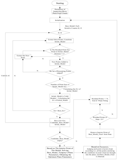
Figure 6.
Improved RANSAC algorithm for planar point cloud fitting process.
3.3. Algorithm Comparison
In order to compare the fitting results of the proposed algorithm with the classical RANSAC, a plane Z = X + 2Y + 1 was set up. 2000 points are randomly selected from the planes and 500 outliers are added. The classical RANSAC algorithm and the algorithm presented in this paper are used for plane fitting, and the parameters are estimated. The standard deviation between the estimated value and the set parameters is calculated, and the results obtained by the two methods are compared. As shown in Table 1.

Table 1.
Comparison of the results of the two algorithms.
Table 1 shows the results of two algorithms. Compared with the classical RANSAC, the algorithm proposed in this paper can eliminate outliers effectively, reduce model errors and improve the accuracy of parameter estimation.
4. Data Acquisition and Experiment
4.1. Experimental Data
The detection method in this paper was fully tested in our experiment. The intelligent robot was used to carry the 3D scanner to detect the track slab in a certain slab factory, and the reliable point cloud data was obtained, and the detection method was fully tested. Table 2 presents the detailed specifications of the robot, and Table 3 presents the detailed specifications of the scanner.
Table 2.
Specifications of KUKA robot KR 90 R3700 prime K.
Table 3.
Specifications of FARO Cobalt Array Imager 5MP.
KUKA robot KR 90 R3700 prime K is used as automatic actuator. The working radius of the robot is 3700 mm and its repetitive positioning accuracy is 0.06 mm, and it can fully meet the requirements of detection range and accuracy. The FARO Cobalt Array Imager 5MP is selected as the data acquisition equipment for track slab surface. The scanning accuracy of the scanner is 0.05 mm, and the point cloud spacing is 0.255 mm. The point cloud data acquired each time is about 5 million. The measuring range of the scanner is 500.0 (length) × 350.0 (width) × 300.0 mm (depth of field), which can basically cover a complete supporting block.
P5600 track slabs were collected at the field. There are 18 supporting blocks on each track slab, and all the supporting blocks plane point cloud data was acquired. The detection system operation and data acquisition in the operation field are shown in Figure 7a,b.
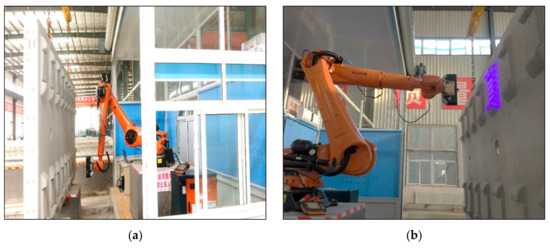
Figure 7.
Operation field: (a) The detection system operation; (b) The data acquisition.
4.2. Experimental Test
First, the track slab model and the geometric characteristics of the supporting block plane were established. Then, the point cloud data was denoised and then registered with the model. Finally, the point cloud data of the supporting block plane was fitted and extracted.
According to the establishment process of the track slab model in Section 2.1, the 3D solid model of the track slab and the supporting block plane feature were created and exported in the IGS format for subsequent data processing. The model is shown in Figure 8.
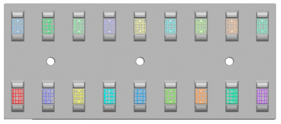
Figure 8.
Track slab model and the establishment of bearing surface features.
Using the point cloud splicing principle in Section 2.2, splicing test was conducted on the point cloud data of 18 supporting block plane of a single-track slab. The splicing results are shown in Figure 9.
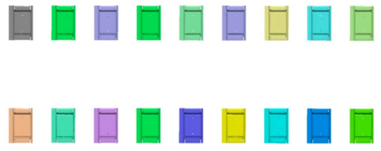
Figure 9.
Point cloud splicing result.
After the point cloud splicing was completed, the point cloud data was further processed by the point cloud registration method in Section 2.4, so that the point clouds and the model were accurately registered, and the registration result is shown in Figure 10.
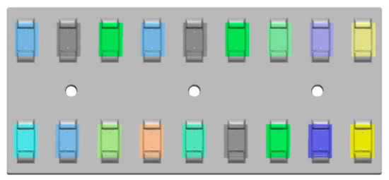
Figure 10.
Results of point cloud and model registration results.
The supporting block plane of the No. 1 supporting block on a P5600 track slab (a total of 18 supporting blocks) was tested by the plane fitting extraction method in Section 3.2. Since the surface of the track slab is flat and smooth, the threshold of the number of intra-points of the improved RANSAC algorithm was set to 95% of the total number of point clouds, and 5% of the extra-points was regarded as noise, and the number of sample points in the optimal estimation model was 1,193,568. Figure 11a,b show the characteristic of the No. 1 supporting block plane, and the result of the point cloud fitting extraction of the No. 1 supporting block plane.
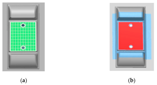
Figure 11.
Characteristic creation and the extraction result: (a) Establishment of the characteristics of the supporting block plane; (b) The supporting block plane fitting extraction.
In order to improve the efficiency of plane fitting calculation, the idea of “local area represents all planes” was adopted, and all basic plane features were cropped according to the scale without affecting the fitting precision, to improve the calculation speed of point cloud data. Within the range of the covered supporting block plane features after cropping, the point cloud was sampled at equal intervals, with a sampling interval of approximately 1.500 mm, and the number of sample points in the optimal estimation model is 6818. The cropping sample fit result is shown in Figure 12.
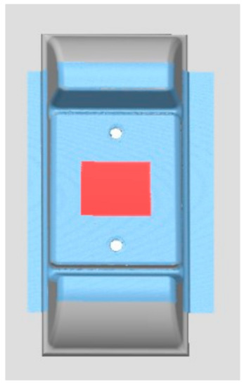
Figure 12.
Result of the cropped supporting block plane fitting extraction.
4.3. Validation
4.3.1. Repeatability of the Detection Method
Ten repeated measurements of the same track slab were carried out to verify the repeatability of the detection method in this paper, and all the supporting block planes were detected.
4.3.2. Accuracy of the Detection Method
In order to verify the accuracy the method, we used the detection indicator related to the supporting block (the slope of the supporting block) to test. The single supporting block model is manufactured according to the design drawings. The slope of the model supporting block relative to the bottom of the track slab is measured 10 times by the contact measurement system with accuracy of (0.9 + L/400) um, and the average measurement value was obtained. Similarly, the slope of the model supporting block was measured 10 times by the method presented in this paper, and the average measured value was obtained. The dimension of the area measured to extract the slope is shown in Figure 13.
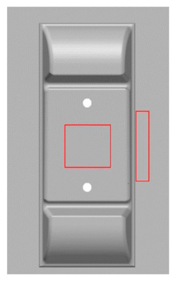
Figure 13.
Dimensions of the area measured to extract the slope.
5. Results and Discussion
5.1. Analysis of Registration Result
In order to analyze the accuracy of the point cloud registration, the No. 1 supporting block is selected for testing. Figure 14 displayed the registration deviation information between point cloud data and standard model, and the deviation value is in the range of −1 mm to 1 mm. As can be seen from Figure 14, the deviation of registration results for most point clouds is ≤±0.300 mm, and the deviation is small in general. According to Table 4, among the 3 million points involved in registration calculation. The points with deviation within ±0.26 mm are about 79% of the total points, and the points with deviation within double standard deviation (±0.5 mm) are about 96% of the total points.
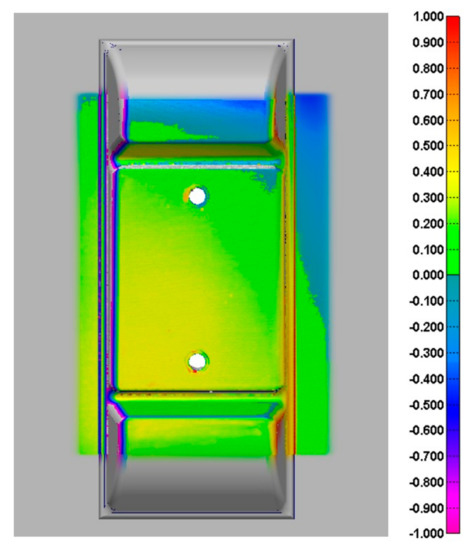
Figure 14.
Registration deviation color map (mm).
Table 4.
Statistical results of registration bias.
5.2. Analysis of Extraction Results of the Supporting Block Plane
Figure 15 depicts the deviation color map of each point in the cropped extraction result to the fitting plane. The color scale in the plane fitting deviation color map indicates the deviation amount from −0.571 mm to 0.064 mm. The color deviation is a visual indication of the quality of the plane fitting. The deviation of the plane fitting is small overall, basically blue and green, that is, the deviation value is between −0.050 mm and 0.060 mm. There are some red and yellow areas in the color picture, which should be small protrusions (red and yellow) on the supporting block plane.
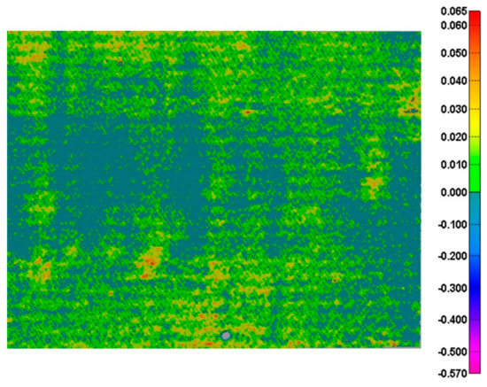
Figure 15.
Plane fitting deviation color map (mm).
In order to quantitatively evaluate the accuracy of the detection method used in this paper, the quality of the supporting block plane was comprehensively analyzed by calculating the flatness, the plane normal vector and the standard deviation of the measuring point in the fitting result of the supporting block plane. The plane extraction parameters of the supporting block plane (taking the No. 1 supporting block as an example) are shown in Table 5.
Table 5.
Supporting block plane parameter extraction result (mm).
The plane obtained by the detection method of this paper has good accuracy, and the standard deviation of the measuring point is 0.029 mm, and the flatness is 0.091 mm, which indicates that the obtained point cloud of the supporting block plane of the track slab has higher precision and is flat. The normal vector of the fitted plane is roughly consistent with the design value (nominal value of the feature), indicating that the plane obtained by the fitting is parallel to the supporting block plane in the track slab model.
Using the same analysis method, the plane fitting quality of the 18 supporting block planes data of the entire track slab was evaluated. The plane fitting process of the 18 supporting block planes after cutting takes less than 2 min, and the fitting result is shown in Figure 16. The statistical results of the standard deviation and flatness deviation of all the supporting block planes are shown in Figure 17. The maximum standard deviation of the measuring points is 0.029 mm, the minimum value is 0.013 mm, the maximum value of flatness is 0.103 mm, and the minimum value of flatness is 0.057 mm. The normal vectors of the fitting plane of the 18 supporting block planes are [0.000 ± 0.001, −0.025 ± 0.001, 1.000 ± 0.001].
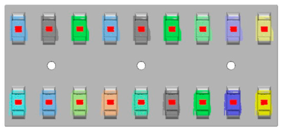
Figure 16.
The 18 supporting block planes fitting results.
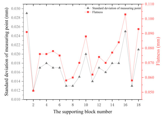
Figure 17.
Statistical results of standard deviation of the measuring points and the flatness.
5.3. Validation Result
5.3.1. Result of Repeated Measurements
All the supporting block planes are extracted, and the flatness and the standard deviation of measuring points of the supporting block planes are calculated. Figure 18 and Figure 19 show the experimental results.
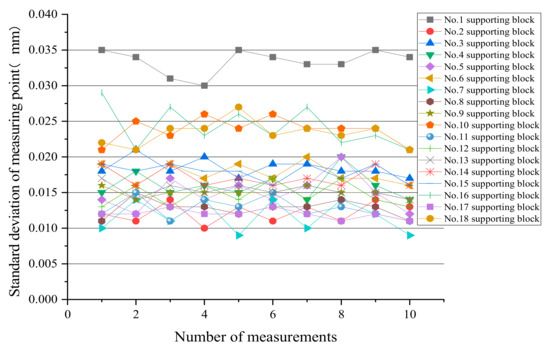
Figure 18.
Standard deviation of measuring points for repeated measurements.
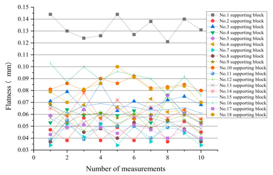
Figure 19.
Flatness of repeated measurements.
The experimental results show that the variation range of standard deviation of each supporting block plane is within 0.010 mm. The difference between the maximum flatness and the minimum flatness of each supporting block plane is within 0.030 mm. It shows that the detection method has high repetitive measurement accuracy.
5.3.2. Analysis of the Accuracy
The angle measurement of the supporting block plane and the bottom of the track slab measured by two detection methods are compared. The measured value of the contact measurement is 1.321°, and the value measured by the method in this paper is 1.342°. The difference between the two measurements is 0.021°. The measurement results prove that the detection method in this paper is accurate. As shown in Table 6.
Table 6.
Comparison of the two methods.
5.4. Experimental Discussion
The experimental results demonstrate the efficiency and accuracy of the proposed method based on the 3D scanner. The point cloud data obtained by the detection method can truly show the information of the surface of the measured object, and can effectively extract the plane point cloud of the supporting block plane. The standard deviation of the measured points and flatness are small, the precision of extraction is high. The method can accurately measure the detection indicators related to the supporting block plane, which proves that the detection method used in this paper is reliable, which lays a good foundation for the subsequent extraction of the track slab detection index parameters.
6. Conclusions
Aimed at the problem of detecting the dimensional deviation of high-speed railway track slabs, this paper proposes a method for detecting the supporting block plane based on a 3D scanner. It is the first time that the three-dimensional scanner and robots have been applied to the detection of the high-speed railway track slab supporting block plane. Compared with traditional measurement method which takes 40 min to complete the detection of a track slab, this method not only guarantees the detection accuracy, but also improves the detection efficiency of track slab, and improves a plane extraction algorithm. We used the robot to carry a 3D scanner to detect the outer dimensions of the track slab and did a lot of experiments. We obtained the real point cloud data of the supporting block planes of track slab and processed the obtained point cloud data. Firstly, the point cloud data was denoised, and the data was spliced according to the physical space location, and then registered with the established model. Finally, the improved RANSAC algorithm was used to extract the point cloud data and analyze the final results. This method provides support for the subsequent automatic extraction of the index of the angle between the supporting block plane and the jaw surface, the slope of the supporting block plane, the features of the height of the convexity, etc. The summary is as follows:
- Compared with the traditional detection method, the detection method can obtain high-quality supporting block detection data, and there is no need to touch the finished slab during the detection process, so as to avoid collision between the detection equipment and its transmission equipment. The detection method is fast and reliable, it takes only 7 min to complete the detection of a track slab, which greatly improves the detection efficiency of the track slab. The requirement for the detection environment is reduced, and the investment of manpower is reduced;
- The point cloud data obtained by the detection method used in this paper can truly reflect the actual situation of the surface of the detected supporting block. The proposed RANSAC algorithm which is robust can efficiently extract the point cloud data of the supporting block planes, and the extraction results are higher. Compared with the design value of the model, the dimensional deviation of the appearance of the track slab is obtained. The establishment of the standard model enhances the visual expression of the detect parameters of the track slab and realizes the control of the dimensional quality;
- The manufacturing process of the CTRSIII track slab and its geometric dimensional accuracy determine that the inspection of the outer dimensions of the track slab belongs to the category of industrial measurement. The minimum allowable deviation of the detect indexes of the track slab dimensions is 0.500 mm. Several detection indicators related to the supporting block plane are detected respectively by the detection method proposed in this paper and the contact measurement. By comparing the measurement results of the two methods, it is concluded that the average error of the method proposed in this paper is less than 0.100 mm and the maximum error is less than 0.200 mm, which meets the accuracy requirements of CRTSIII track slab detection.
The detection method has wide application prospects in the field of railway component detection. In future work, we will improve the detection method, add other sensors, and propose a multi-sensor integrated detection method.
Author Contributions
Conceptualization, X.C., F.Q. and X.Z.; Methodology, X.C., C.X. and J.B.; Software, X.C. and J.B.; Validation, Y.H. and C.X.; Formal Analysis, X.Z., Y.H. and J.B.; Investigation, F.Q. and J.B.; Writing, X.C.
Funding
This research received no external funding.
Acknowledgments
The authors would like to thank Baolin Luo for the helpful technical support and Changyao Ye for the helpful discussion, as well as Chao Luo and Yuan Li for doing the experiments.
Conflicts of Interest
The authors declare no conflict of interest.
References
- Lu, S. On Fast Precise Measuring Technologies of Track Slabs of High-Speed Railway. Master’s Thesis, PLA Information Engineering University, Zhengzhou, China, 2012. [Google Scholar]
- Novakovic, G.; Lazar, A.; Kovacic, S.; Vulic, M. The usability of terrestrial 3D laser scanning technology for tunnel clearance analysis application. Appl. Mech. Mater. 2014, 683, 219–224. [Google Scholar] [CrossRef]
- Yang, T.; Song, Y.; Zhang, W.; Li, F. Acoustic emission detection using intensity-modulated DFB fiber laser sensor. Chin. Opt. Lett. 2016, 14, 46–49. [Google Scholar]
- Labecki, P.; Nowicki, M.; Skrzypczynski, P. Characterization of a compact laser scanner as a sensor for legged mobile robots. Manag. Prod. Eng. Rev. 2012, 3, 45–52. [Google Scholar]
- Govindarajan, M.S.; Wang, J.; Post, B.; Fox, A. Target Design and Recognition for 2-D Localization of Indoor Mobile Robots Using a Laser Sensor. IFAC Proc. Vol. 2013, 46, 67–74. [Google Scholar] [CrossRef]
- Zou, X.; Zou, H.; Lu, J. Virtual manipulator-based binocular stereo vision positioning system and errors modelling. Mach. Vis. Appl. 2012, 23, 43–63. [Google Scholar] [CrossRef]
- Lv, Z.; Zhang, Z. Build 3D scanner system based on binocular stereo vision. J. Comput. 2012, 7, 399–404. [Google Scholar] [CrossRef]
- Mueller, T.; Jordan, M.; Schneider, T.; Poesch, A.; Reithmeier, E. Measurement of steep edges and undercuts in confocal microscopy. Micron 2016, 84, 79–95. [Google Scholar] [CrossRef]
- Kho, K.W.; Shen, Z.; Malini, O. Hyper-spectral confocal nano-imaging with a 2D super-lens. Opt. Express. 2011, 19, 2502–2518. [Google Scholar] [CrossRef]
- Yang, W. Automatic welding robot path planning and application instance based on 3D vision technology. Electric. Wel. Mach. 2015, 45, 37–42. [Google Scholar]
- Ahmed, S.M.; Yan, Z.T.; Chee, M.C.; AI Mamun, A. Edge and Corner Detection for Unorganized 3D Point Clouds with Application to Robotic Welding. In Proceedings of the IEEE International Conference on Intelligent Robots and Systems, Madrid, Spain, 1–5 October 2018; pp. 7350–7355. [Google Scholar]
- Kim, M.; Cheng, J.C.P.; Sohn, H.; Chang, C.C. A framework for dimensional and surface quality assessment of precast concrete elements using BIM and 3D laser scanning. Autom. Constr. 2015, 49, 225–238. [Google Scholar] [CrossRef]
- Song, L.; Sun, S.; Yang, Y.; Zhu, X.; Guo, Q.; Yang, H. A Multi-View Stereo Measurement System Based on a Laser Scanner for Fine Workpieces. Sensors 2019, 19, 381. [Google Scholar] [CrossRef]
- Simler, C.; Berndt, D.; Teutsch, C. Bimodal Model-based 3D Vision and Defect Detection for Free-form Surface Inspection. In Proceedings of the VISAPP International Conference on Computer Vision Theory and Applications, Porto, Portugal, 27 February–1 March 2017; pp. 451–458. [Google Scholar]
- Jovancevic, I.; Pham, H.; Orteu, J.; Gilblas, R.; Harvent, J.; Maurice, X.; Brethes, L. 3D Point Cloud Analysis for Detection and Characterization of Defects on Airplane Exterior Surface. J. Nondestruct. Eval. 2017, 36, 74. [Google Scholar] [CrossRef]
- Reyno, T.; Marsden, C.; Wowk, D. Surface damage evaluation of honeycomb sandwich aircraft panels using 3D scanning technology. NDT&E Int. 2018, 97, 11–19. [Google Scholar]
- Zhou, S.; Guo, Y.; Gao, C. Development of a Laser-Based Geometric Measurement System for Large-Scale Conical. Chin. J. Lasers 2014, 41, 0508008. [Google Scholar] [CrossRef]
- Javier, B.F.; Jose, A.J.; Guillomia, D.; Santolaria, J. 3D Geometrical Inspection of Complex Geometry Parts Using a Novel Laser Triangulation Sensor and a Robot. Sensors 2011, 11, 90–110. [Google Scholar]
- Fan, S. Research on the Key Technologies of Track Slab Quick Detection Based on Digital Photogrammetry. Ph.D. Thesis, China University of Mining and Technology, Xuzhou, China, 2014. [Google Scholar]
- Xue, F. Design and Application of Rapid Detection system for Key Geometric Dimension of Track Slab. Railw. Eng. 2016, 4, 118–122. [Google Scholar]
- Xu, L. Research on Quick Detection Track Slab of High-Speed Railway. Railw. Invest. Surv. 2016, 42, 5–8. [Google Scholar]
- Yang, M.; Shen, X. Application of 3D Laser Scanning Technology in the Detection of CRTS III Track Slab. In Proceedings of the Third China BIM Academic Conference, Shanghai, China, 4–5 November 2017. [Google Scholar]
- Gong, Y. Research on 3D Modeling of Indoor Objects and Scenes Based on RGBD Data. Master’s Thesis, Nanjing University, Nanjing, China, 2015. [Google Scholar]
- Zhang, K.; Qiao, S.; Zhou, W. Point Cloud Segmentation Based on 3-dimensional Shape Matching. Laser Optoelectron. Prog. 2018, 55, 1–22. [Google Scholar]
- Duan, C.; Chen, S.; Kovacevic, J. Weighted Multi-projection: 3D Point Cloud Denoising with Estimated Tangent Planes. In Proceedings of the 2018 IEEE Global Conference on Signal and Information Processing (GlobalSIP), Anaheim, CA, USA, 26–29 November 2018. [Google Scholar]
- Liu, L. Feature Extraction and Segmentation for 3D Meshes. Master’s Thesis, East China Normal University, Shanghai, China, 2015. [Google Scholar]
- Lv, Y.; Wan, C. A Denoising Method by Layering for Terrain Point Cloud from 3D Laser Scanner. J. Geomatics Sci. Technol. 2014, 31, 501–504. [Google Scholar]
- Fleishman, S.; Drori, I.; Cohen-Or, D. Bilateral mesh denoising. ACM Trans. Graph. 2003, 22, 950–953. [Google Scholar] [CrossRef]
- Song, P. Research on Algorithm for Registration of 3D Point Cloud and CAD Model. Master’s Thesis, University of Science and Technology of China, Hefei, China, 2016. [Google Scholar]
- Zeng, A.; Ming, F. The Rigorous Model for Similarity Transformation under Intra-frame and Inter-Frame Covariance. Acta Geod. Er Cartogr. Sin. 2017, 46, 16–25. [Google Scholar]
- ISO. Manipulating Industrial Robots-Performance Criteria and Related Test Methods; ISO9283:1998(E); ISO: Geneva, Switzerland, 1998. [Google Scholar]
- Li, W.; Song, P. A modified ICP algorithm based on dynamic adjustment factor for registration of point cloud and CAD model. Pattern Recognit. Lett. 2015, 65, 88–94. [Google Scholar] [CrossRef]
- Nguyen, C.H.P.; Choi, Y. Comparison of point cloud data and 3D CAD data for on-site dimensional inspection of industrial plant piping systems. Autom. Constr. 2018, 91, 44–52. [Google Scholar] [CrossRef]
- Hattab, A.; Taubin, G. 3D Rigid Registration of Cad Point-Clouds. In Proceedings of the IEEE International Conference on Computing Sciences and Engineering, Kuwait City, Kuwait, 11–13 March 2018; pp. 1–6. [Google Scholar]
- Yang, G.; Zeng, R.; Dong, A. Research and Application of 3D Face Modeling Algorithm Based on ICP Accurate Alignment; Journal of Physics: Conference Series; Tseng, J., Kotenko, I., Eds.; IOP Publishing: Bristol, UK, 2018; Volume 1069, p. 012149. [Google Scholar]
- Boulaassal, H.; Landes, T.; Grussenmeyer, P. Automatic Extraction of Planar Clusters and their Contours on Building Fasigmavades Recorded by Terrestrial Laser Scanner. Int. J. Archit. Comput. 2009, 7, 1–20. [Google Scholar] [CrossRef]
- Bo, H. Accuracy Comparison and Analysis of Three Kinds of Point Cloud Data Plane Fitting Methods. Geomat. Spat Inf. Technol. 2018, 41, 206–208. [Google Scholar]
- Wang, C.; Tanahashi, H.; Hirayu, H. Comparison of local plane fitting methods for range data. In Proceedings of the IEEE Computer Society Conference on Computer Vision and Pattern Recognition, Kauai, HI, USA, 8–14 December 2001; Volume 1. [Google Scholar]
- Shakarji, C.M.; Srinivasan, V. Convexity and Optimality Conditions for Constrained Least-Squares Fitting of Planes and Parallel Planes to Establish Datums. J. Comput. Inf. Sci. Eng. 2019, 19, 0110021. [Google Scholar] [CrossRef]
- Bauer, J.; Karner, K.; Schindler, K.; Klaus, A.; Zach, C. Segmentation of building from dense 3D point-clouds. In Proceedings of the ISPRS Workshop Laser Scanning, Enschede, The Netherlands, 12–14 September 2005. [Google Scholar]
- Schnabel, R.; Wahl, R.; Klein, R. Efficient Ransac for point-cloud shape detection. In Computer Graphics Forum; Blackwell Publishing Ltd.: Oxford, UK, 2007; Volume 26, pp. 214–226. [Google Scholar]
- Tarsha-Kurdi, F.; Landes, T.; Grussenmeyer, P. Extended RANSAC algorithm for automatic detection of building roof planes from LiDAR data. Photogram J. Finl. 2008, 21, 97–109. [Google Scholar]
- Chen, F.; Wang, R. Fast RANSAC with Preview Model Parameters Evaluation. J. Softw. 2005, 16, 1431–1437. [Google Scholar] [CrossRef]
- Dorninger, P.; Pfeifer, N. A Comprehensive Automated 3D Approach for Building Extraction, Reconstruction, and Regularization from Airborne Laser Scanning Point Clouds. Sensors 2008, 8, 7323–7343. [Google Scholar] [CrossRef]
- Schnabel, R.; Wessel, R.; Wahl, R. Shape Recognition in 3D Point Clouds. In Proceedings of the 16th International Conference in Central Europe on Computer Graphics, Visualization and Computer Vision in co-operation with Eurographics, University of West Bohemia, Plzen, Czech Republic, 4–7 February 2008; pp. 65–72. [Google Scholar]
- Awwad, T.M.; Zhu, Q.; Du, Z. An Improved Segementation Approach for Planar Surfaces from Unstructured 3D Point Clouds. Photogramm. Rec. 2010, 25, 5–23. [Google Scholar] [CrossRef]


© 2019 by the authors. Licensee MDPI, Basel, Switzerland. This article is an open access article distributed under the terms and conditions of the Creative Commons Attribution (CC BY) license (http://creativecommons.org/licenses/by/4.0/).