Article

Development of a Novel Shaft Dryer for Coal-Based Green Needle Coke Drying Process

1
School of Energy and Environmental Engineering, University of Science and Technology Beijing, Beijing 100083, China
2
Sinosteel Anshan Research Institute of Thermo-Energy Co., Ltd., Anshan 114044, Liaoning, China
3
Department of Thermal Engineering, School of Metallurgy, Northeastern University, Shenyang 110819, Liaoning, China
4
State Environmental Protection Key Laboratory of Eco-Industry, Northeastern University, Shenyang 110819, Liaoning, China
*
Author to whom correspondence should be addressed.
Appl. Sci. 2019, 9(16), 3301; https://doi.org/10.3390/app9163301
Submission received: 22 July 2019 / Revised: 1 August 2019 / Accepted: 8 August 2019 / Published: 12 August 2019
(This article belongs to the Section Applied Industrial Technologies)

Abstract

:

Featured Application

The energy efficient and environmentally friendly shaft dryer can be applied for drying green cokes during the needle coke production process.

Abstract

The industry of coal-based green needle coke develops rapidly in recent years. The green coke produced by the delayed coking process usually has a moisture content of 10%–25%, which damages the calcining kiln and needle coke quality. A standing dehydration tank is currently used to reduce the moisture content of green coke. However, this process has several weaknesses such as unstable operation, large land area occupation, and low productivity. To solve this issue, a novel drying system with a shaft dryer proposed in this work is suitable for green coke drying. Moreover, the performances of the green coke are investigated to design the proposed shaft dryer. The experimental result shows that the average vertex angle of the pile of green cokes is 109.2°. The pressure drop of the dryer increases linearly with the green coke bed height, and the green coke with a larger size has a smaller pressure drop. The specific pressure drops are 5714, 5554, 5354, and 5114 Pa/m, with median green coke sizes of 26.85, 29.00, 30.45, and 31.80 mm, respectively. Tooth spacing is another important parameter which influences the mass of green coke leakage. The optimal tooth spacing and rotary speed of the rollers are determined by the required production yield.

Graphical Abstract

1. Introduction

Needle coke, as an important carbon material, can be classified into two types, i.e., petroleum-based needle coke [1] with heavy oil as the raw materials, and coal-based needle coke [2] with coal tar, coal pitch, or their fractions as the raw materials. Initially, petroleum-based needle coke occupies the dominant position, while the production of coal-based needle coke is greatly accelerated due to the high price and lightening production of petroleum in the recent years.
Green manufacturing and cleaner production [3] have become one prominent feature of sustainable development. Especially in the context of carbon trade and carbon tax [4,5], energy conservation and emissions reduction are definitely the key issues of various industrial processes, such as ceramic production [6], ironmaking [7], sintering [8], and power generation [9]; and the needle coke drying process should be no exception. Coal-based needle coke is a perfect material for the manufacturing of the ultra-high-power electrode used in the compact steelmaking process. Iron and steel are traditionally produced with iron ores as material inputs and coal-based energies as energy inputs [10], which has a high energy consumption and heavy environmental pollution [11]. Contrarily, the compact steelmaking process using scrap as the main material input and electricity as the main energy source attracts more and more attraction [12]. Coal-based needle coke also serves as anode materials of lithium-ion batteries. The use of ultra-high-power electrode made from coal-based needle coke can reduce the smelting time by 10% to 20%, resulting in the electrode consumption and electricity consumption. In addition, with the rapid development of lithium-ion battery [13], the demand for anode materials increases obviously, which results in the mushroom of green coke of coal-based needle coke [14].
The production of coal-based needle coke consists of three main processes: pretreatment of raw materials, delayed coking [15], and calcining [16]. The coke produced by a delayed coking process is called green needle coke, while called calcined needle coke if produced by a calcining process. For the coking process, the size of dust emissions is mainly 3.3 to 9.0 μm, and the main chemical components are C, SiO2, Al2O3, S, CaO, and TFe, with contents of 76.30%–81.30%, 5.36%–5.91%, 3.96%–4.26%, 1.15%–1.34%, 0.52%–1.59%, and 0.81%–1.34%, respectively [17]. Green coke serves as the material input of the calcining process, and its drying degree directly affects the energy consumption and the quality of the final product of the calcining process. The green coke discharged from the delayed coking unit has a moisture content of 10% to 25%. If the green coke with such a high moisture content enters the rotary kiln to be calcined, the following negative aspects will occur from whole system and life cycle perspectives [18]: (i) the temperature of the kiln tail will be lower, and the parameters such as kiln pressure, air amount, and fuel ratio have to be adjusted frequently, which will cause difficulty in operating the rotary kiln; (ii) more thermal energy will be consumed [19] in the calcining process; and (iii) there is a greater possibility of being exploded to scraps, compared with green coke with low moisture content, resulting in small particle size of calcined coke.
To reduce the moisture content of green coke, several standing dehydration tanks are usually used in the real-world production process to maintain the moisture content of green coke below 5% in 5 days. But in winter, the water escapes slower from the coke surface and internal pores [20], then the moisture content may reach 8% due to the low temperature, which results in an unstable operation of the rotary calcining kiln, and further affects the energy consumption and calcined coke quality. In addition, the dehydration tanks, with a height of approximately 10 m and a diameter of 2 to 4 m, and the large inclination belt conveyor occupy a large land area with a resultant capital investment cost. Thus, a new drying system should be developed to accelerate the drying process and stabilize the final moisture content of green cokes.
Several drying methods are widely used in high energy-consuming industrial processes [21], including rotary dryer [22,23], tubular drier [24], airflow dryer [25], fluidized-bed dryer [26], and microwave dryer [27]. Table 1 summarizes the characteristics of the drying methods mentioned in previous studies when they used for drying green coke. It is indicated that the dryers widely used in other industries are not suitable for green coke drying. Given the advantageous material flow and heat transfer of shaft facilities [28,29,30], this work aims at designing a novel efficient drying system with a shaft dryer that is suitable for green coke drying, with sound energy usage [31] and low environmental impact [32,33]. In addition, key characteristics of the green coke, including particle size distribution [34], initial moisture content, vertex angle, pressure drop scheme [35], and the discharge characteristics, are essential to determine the parameters of the designed dryer [36]. However, little information can be found on this topic. This work investigates these characteristics experimentally and provides detailed data that are important to design the proposed shaft dryer for drying green coke.

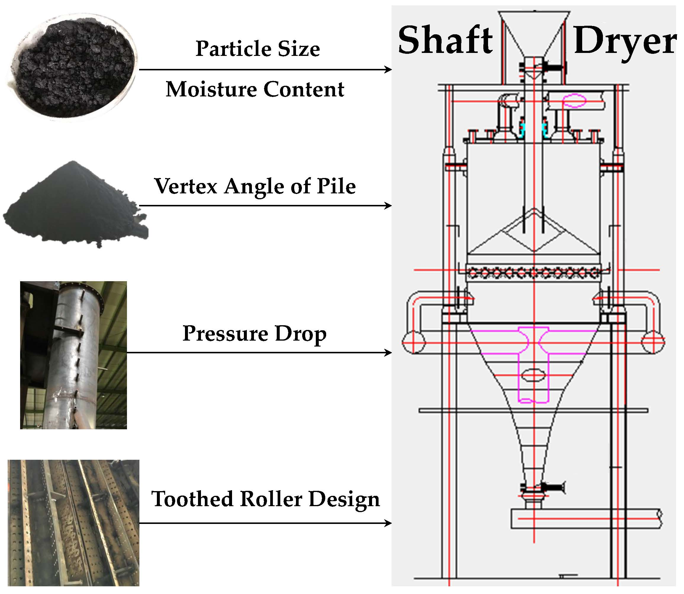
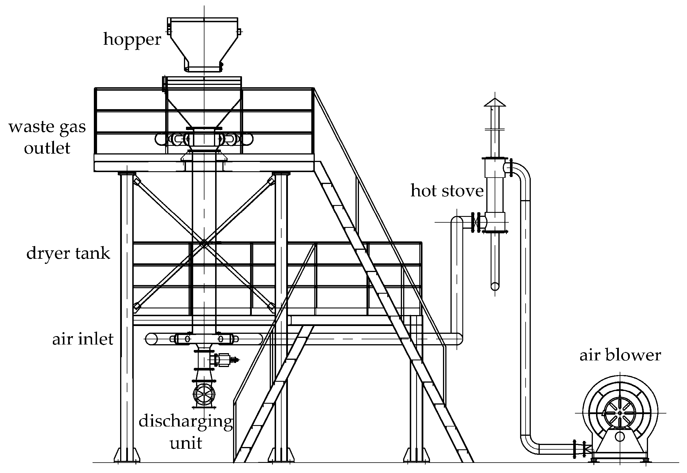
2. Design of the Novel Drying System and Shaft Dryer

To overcome the shortcomings of currently used dryers for drying green coke, this work proposes a novel drying system, as shown in Figure 1. The proposed drying system consists of 10 main components: primary air blower, secondary air blower, combustion chamber, hot stove, belt conveyor, shaft dryer, helical conveyor, bucket elevator, transfer hopper, and exhaust fan. Fuel gas and the air from primary air blower are mixed and fired in the combustion chamber. The generated high-temperature flue gas at 1300 °C is sent to the hot stove, inside which the high-temperature flue gas is mixed with the low-temperature air from the secondary air blower to get the medium-temperature gas at 450 to 500 °C. The medium gas is then piped into the bottom of the shaft dryer. A constant feeder discharges the wet green cokes to a belt conveyor, through which the wet green cokes are transferred to the top hopper of the shaft dryer at a constant speed. Next, the wet green cokes are fed into the dryer uniformly to exchange heat with the medium-temperature gas in an energy-efficient, direct-contact, and counter-current way [37]. The discharging unit at the bottom of the shaft dryer controls the discharge speed and loosens the green cokes to prevent blocking the dryer. The discharged final green cokes enter a helical conveyor and are then conveyed to a bucket elevator, which connects the inlet of a transfer hopper. When the temperature of the green cokes is lower than 70 °C, the final product is packaged. The waste gas from the shaft dryer is treated via a bag filter before emitted into the atmosphere.
Figure 2 depicts the layout of the shaft dryer. The shaft dryer is principally based on the moving bed technology [38,39]. With medium-temperature gas as the heat source, the refractory material can be totally saved, and the over-burnt and pollution caused by the spalled refractory material can be avoided. The wet green cokes are uniformly placed in the shaft dryer and discharged by gravity. Thus, the mechanical transmission unit can be removed, resulting in the low failure of the system. In addition, because no pneumatic conveying of the green cokes occurs inside the shaft dryer, hence there is no need to crush the green cokes to meet a strict limitation of the particle size.
A 20,000 t/y shaft dryer is selected as a case analysis. The dryer runs 300 d/y and 24 h/d. The initial moisture is 10%, and the final moisture is 1%. The target temperature of dried green cokes is 80 °C, and the flow rate of flue gas is 5000 m3/h. The average specific heat capacities of green cokes and flue gas are 0.808 and 1.4 kJ/(kg·°C), respectively. It can be calculated that the energy efficiency is 80%. Given the influence of heat loss, the estimated that an energy efficiency of 65%–75% could be achieved in practice. The corresponding economic and environmental assessment [40] can also be conduction based on the design parameters. The characteristics of the novel shaft dryer can be summarized as follows:
  • It has a simple structure and no mechanical transmission unit, making it easy to maintain, with low noise while operating and low failure rates.
  • It is a wholly-sealed system, and thus the energy efficiency can be as high as 65%–75% with no leak of environmental pollutants.
  • It can be built by using less metal, less land area, lower capital investment cost, compared with other drying methods.
  • It uses medium-temperature gas as the heat source, which will not cause the over-burnt quality of green cokes.
  • It does not need liner inside the shaft dryer, ensuring that final green cokes have good quality.
  • It has a low breakage rate of green coke because of the low-speed flow of green coke inside the shaft dryer, which further reduces the amount of dust and the cost of environmental assets.
  • It can easily adjust the residence time and the resultant moisture content of green cokes.
  • It has less strict requirement on the particle size of green cokes because of the use of gravity discharging and related units.

3. Materials and Experimental Methods

As a novel dryer, the shaft dryer can be quantitatively designed based on the characteristics of green cokes, which affect the structural and operational parameters of the dryer [36]. Most importantly, the particle size distribution and pressure drop scheme determine the selection of air blowers and the affiliated motors. The initial moisture content determines the residence time of the green cokes and the speed of the discharging unit and the helical conveyor. The vertex angle of pile affects the design of the distributor of the shaft dryer. The discharge characteristics of the toothed roller are determined by the productivity of upstream processes. To provide more detailed data to fill in the gap between concept and application, the following experiments are conducted in this work.

3.1. Materials

The particle size of green cokes discharged from the delayed coking process is less than 70 mm, which can be charged into the shaft dryer directly without any further processing. Thus, in this work, 10-, 30-, and 50-mm meshes were used for the screening of green cokes. The particle size distribution of green cokes used as the raw material in this work are shown in Table 2.

3.2. Experimental Methods

3.2.1. Method to Determine the Initial Moisture Content

A weighing bottle was used to weigh a certain mass of wet green coke. After a 5-min preheating of an oven at 110 °C, the weighing bottle was uncovered and put in the drying oven for 2 h. Then, the weighing bottle was taken out, immediately covered with its lid, and put in a desiccator until it cools to indoor temperature. Finally, a desiccation check was conducted for 30 min. The initial moisture content can be calculated by
ω = m 0 m 1 m 0 × 100 % ,
where ω is the initial moisture content, %; m0 and m1 are the mass of green cokes before and after the drying experiment, respectively, measured in g.

3.2.2. Method to Determine the Vertex Angle of Pile of Green Cokes

When green cokes are poured on a surface, they usually form a conical pile. The angle that the surface of the pile of green cokes makes with vertical is referred to as the half-vertex angle. The vertex angle of pile is very important to design the structure of the green coke distributor of the shaft dryer. As shown in Figure 3, the vertical height and hypotenuse can be measured by using a ruler. Then, the vertex angle of the pile can be calculated by
α = 2 · arccos ( h / l ) .
where α is the vertex angle of the piles of green cokes, h is the vertical height, and l is the hypotenuse.

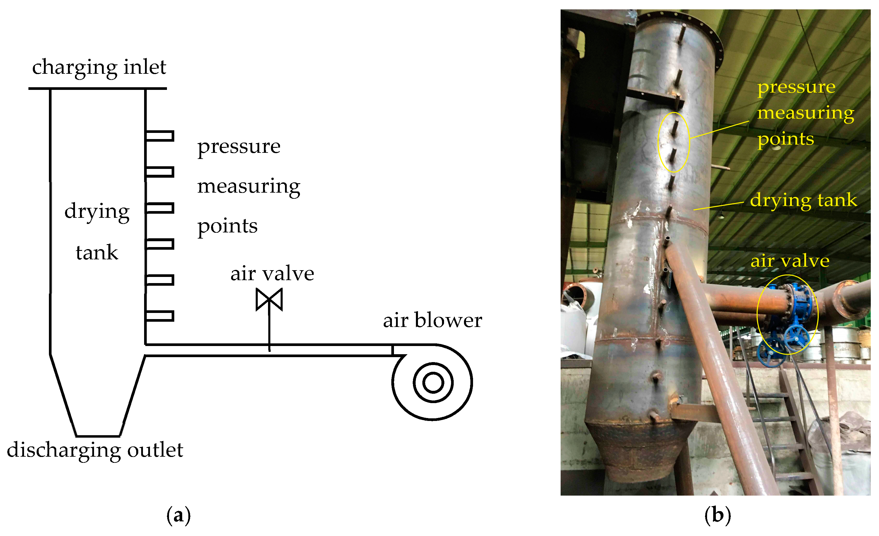
3.2.3. Method to Determine the Pressure Drop Characteristics

The air blower is a component of this proposed drying system and its capacity and operating parameters significantly influence the gas flow and heat transfer inside the shaft dryer. A pressure drop experiment was also conducted in this work by using an apparatus shown in Figure 4. The diameter of this apparatus is 800 mm. Wet green cokes were filled in the dryer tank, and the packing height was 1500 mm above the air inlet pipe. The outer and inner diameters of the air inlet pipe are 219 mm and 200 mm, respectively. The pressure drop was measured by using a differential pressure transmitter, and the flow rate of air was measured by a gas flowmeter.

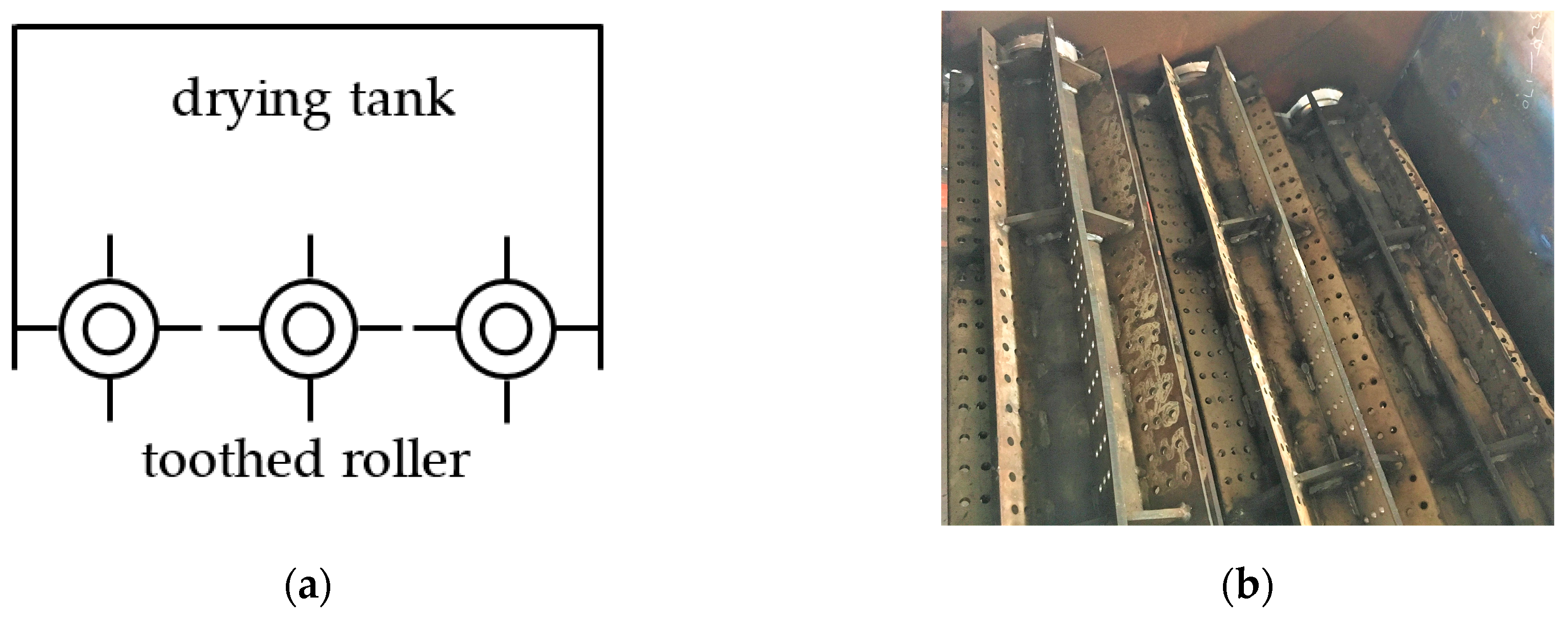
3.2.4. Method to Determine the Discharge Characteristics of the Toothed Roller

The toothed roller is specially designed for discharging the final green cokes. It is used for controlling the discharge speed of green cokes. Thus, in this work, the rational tooth spacing and rotary speed were experimentally investigated as shown in Figure 5.
The green cokes’ leakage can be measured as follows. The minimum tooth spacing was set as 30 mm, and the distance between the rollers and the top of the green coke stock was 1500 mm. The green cokes whose particle size is larger than 30 mm were screened out, and the left ones smaller than 30 mm were hung to 3 m above the experimental apparatus. After discharging, the green coke leakage was weighed. The experiment can be repeated by adjusting the minimum tooth spacing to 10 and 20 mm.

4. Results and Discussions

Figure 6 shows three kinds of green coke with different size at the initial moisture content of 22%. As the moisture content relates to the granulation properties [41], the lump, fine, and mixed green coke particles with the median size of 35.0, 1.0, and 21.4 mm, respectively, were selected in this experiment. For mixed green coke, the lump green coke accounts for 60%. Figure 7 shows the relationship between moisture content and gas temperature. With the increase in gas temperature, the moisture content reduces remarkably. For drying gas at 350 °C, the moisture content of lump green coke was 6.82%, while that of fine and mixed green cokes could be as low as 1.38% and 0.40%, respectively. Though lump green coke can be dried by using this shaft dryer, it may consume more energy. It can be found that the mixed green coke has the lowest moisture content because this plan has the best gas flow and heat transfer effect. Thus, mixed green coke is a good option in the real drying process.
Table 3 lists the measurement data and results of the vertex angle of the pile of green cokes of five reduplicative experiments. The vertex angle of the pile is another key property of coke besides the particle size distribution and strength [42]. It is shown that the average vertex angle of pile of green cokes is 109.2°, which is very important to design the structure of the distributor.
To investigate the pressure drop characteristics of green cokes, a fixed bed experiment was conducted. Four sets of green cokes as shown in Table 2 were used in this experiment. The relationship between the pressure drop and bed height is shown in Figure 8. An approximately linear relationship is shown and the pressure drop increases with the increase in bed height. The pressure characteristics vary with the particle sizes [43]. The green coke with larger size has a less pressure drop, because of its relatively large void ratio and good gas flow behavior. When the bed height is 1250 mm, the total pressure drops of the four test sets with median green coke size of 26.85, 29.00, 30.45, and 31.80 mm are 6104, 5944, 5744, and 5504 Pa, respectively. It can be found from Figure 9 that the specific pressure drops of the four test sets are 5714, 5554, 5354, and 5114 Pa/m, respectively.
Figure 10 shows the relationship between the mass of green coke leakage and tooth spacing based on the results of five repeated experiments. It can be seen that the green coke leakage increases with the increase in tooth spacing. Given that the rolls may experience a horizontal movement because of the axial compression among green cokes when discharging, the initial green coke leakage should be small and adjusted to its reasonable leakage tardily. The optimal tooth spacing can be determined according to the requirement of production yield.
The optimal rotary speed can be determined as follows. The mixed green cokes with the maximum particle size as 70 mm were filled in the drying tank. The rolls horizontally set in the shaft dryer were rotated by 180° at a constantly rotary speed. After discharging, the green coke leakage was weighed. Then, the rotary speed of the rollers can be obtained by the mass of leakage and the required leakage per minute in real production. With the development of Industrial 4.0 [44], the tooth spacing and rotary speed of the rollers can be adjusted according to the present working conditions.

5. Conclusions

(1) A novel drying system and a shaft dryer are proposed for drying the wet coal-based green needle cokes by using medium-temperature gas as a heat source in an energy-efficient, direct-contact, and counter-current way.
(2) The moisture content of green cokes reduces remarkably with the increase in gas temperature. Compared with lump and fine green cokes, mixed green coke has the lowest moisture content and is recommended in the real drying process. The average vertex angle of the pile of green cokes is 109.2°, which is an important parameter for the structure of the shaft dryer distributor.
(3) An approximately linear relationship is gotten between the pressure drop and the green coke bed height. The green coke with larger size has a less pressure drop. The specific pressure drops of the four test sets with median green coke size of 26.85, 29.00, 30.45, and 31.80 mm are 5714, 5554, 5354, and 5114 Pa/m, respectively.
(4) Tooth spacing affects the mass of green coke leakage. The larger the spacing, the more the leakage. In real production, the optimal tooth spacing and rotary speed of the rollers should be determined by the required production yield.

Author Contributions

Conceptualization, G.X., X.Z. and J.C.; methodology, G.X.; validation, G.X., K.Z. and S.Z.; formal analysis, G.X. and W.S.; investigation, K.Z. and S.Z.; data curation, G.X.; writing—original draft preparation, W.S. and G.X.; writing—review and editing, W.S. and G.X.; visualization, W.S.; supervision, X.Z. and J.C.; project administration, G.X.; funding acquisition, G.X.

Funding

This research was funded by the National Key R&D Program of China, grant number 2017YFB0603502; the National Natural Science Foundation of China, grant number 51734004; and the Liaoning Revitalization Talents Program, grant number XLYC1805016.

Conflicts of Interest

The authors declare no conflict of interest.

References

  1. Halim, H.P.; Im, J.S.; Lee, C.W. Preparation of needle coke from petroleum by-products. Carbon Lett. 2013, 14, 152–161. [Google Scholar] [CrossRef]
  2. Wang, R.; Lu, G.; Qiao, W.; Yu, J. Catalytic graphitization of coal-based carbon materials with light rare earth elements. Langmuir 2016, 32, 8583–8592. [Google Scholar] [CrossRef] [PubMed]
  3. Ma, S.; Zhang, Y.; Lv, J.; Yang, H.; Wu, J. Energy-cyber-physical system enabled management for energy-intensive manufacturing industries. J. Clean. Prod. 2019, 226, 892–903. [Google Scholar] [CrossRef]
  4. Wang, J.; Gu, F.; Liu, Y.; Fan, Y.; Guo, J. Bidirectional interactions between trading behaviors and carbon prices in European Union emission trading scheme. J. Clean. Prod. 2019, 224, 435–443. [Google Scholar] [CrossRef]
  5. Guo, J.; Su, B.; Yang, G.; Feng, L.; Liu, Y.; Gu, F. How Do Verified Emissions Announcements Affect the Comoves between Trading Behaviors and Carbon Prices? Evidence from EU ETS. Sustainability 2018, 10, 3255. [Google Scholar] [CrossRef]
  6. Lv, J.; Gu, F.; Zhang, W.; Guo, J. Life cycle assessment and life cycle costing of sanitary ware manufacturing: A case study in China. J. Clean. Prod. 2019, 238, 117938. [Google Scholar] [CrossRef]
  7. Li, X.; Sun, W.; Zhao, L.; Cai, J. Emission characterization of particulate matter in the ironmaking process. Environ. Technol. 2019, 40, 282–292. [Google Scholar] [CrossRef]
  8. Zhao, L.; Sun, W.; Li, X.; Ye, Z.; Huang, J.; Zhang, G.; Cai, J. Assessment of particulate emissions from a sinter plant in steelmaking works in China. Environ. Monit. Assess. 2017, 189, 368. [Google Scholar] [CrossRef]
  9. Xu, X.; Li, K.; Jia, H.; Yu, X.; Deng, J.; Mu, Y. Data-driven dynamic modeling of coupled thermal and electric outputs of microturbines. IEEE Trans. Smart Grid 2016, 9, 1387–1396. [Google Scholar] [CrossRef]
  10. Sun, W.; Wang, Y.; Zhang, F.; Zhao, Y. Dynamic allocation of surplus byproduct gas in steel plant by dynamic programming with reduced state space algorithm. Eng. Optim. 2018, 50, 1578–1592. [Google Scholar] [CrossRef]
  11. Sun, W.; Xu, X.; Lv, Z.; Mao, H.; Wu, J. Environmental impact assessment of wastewater discharge with multi-pollutants from iron and steel industry. J. Environ. Manag. 2019, 245, 210–215. [Google Scholar] [CrossRef]
  12. Li, X.; Sun, W.; Zhao, L.; Cai, J. Material metabolism and environmental emissions of BF-BOF and EAF steel production routes. Miner. Process. Extr. Metall. Rev. 2018, 39, 50–58. [Google Scholar] [CrossRef]
  13. Zubi, G.; Dufo-López, R.; Carvalho, M.; Pasaoglu, G. The lithium-ion battery: State of the art and future perspectives. Renew. Sustain. Energy Rev. 2018, 89, 292–308. [Google Scholar] [CrossRef]
  14. Zhu, Y.; Zhao, C.; Xu, Y.; Hu, C.; Zhao, X. Preparation and Characterization of Coal Pitch-Based Needle Coke (Part I): The Effects of Aromatic Index (fa) in Refined Coal Pitch. Energy Fuels 2019, 33, 3456–3464. [Google Scholar] [CrossRef]
  15. Kondrasheva, N.K.; Rudko, V.A.; Nazarenko, M.Y.; Povarov, V.G.; Derkunskii, I.; Konoplin, R.; Gabdulkhakov, R. Influence of parameters of delayed coking process and subsequent calcination on properties and morphology petroleum needle coke from decant oil mixture of west Siberian oil. Energy Fuels 2019, 33, 6373–6379. [Google Scholar] [CrossRef]
  16. Hardin, E.E.; Ellis, P.J.; Beilharz, C.L.; McCoy, L. A Comprehensive Review of the Effects of Calcination at Various Temperatures on Coke Structure and Properties Part II. In Essential Readings in Light Metals; Springer Science and Business Media LLC: Cham, Switzerland, 2016; Volume 4, pp. 73–83. [Google Scholar]
  17. Wang, Y.H.; Zhao, L.; Sun, W.Q.; Ye, Z.; Cai, J.J. Characteristics of particulate matter emissions from the coking process. Environ. Sci. 2018, 39, 5359–5364. [Google Scholar]
  18. Zhang, W.; Gu, F.; Guo, J. Can smart factories bring environmental benefits to their products? A case study of household refrigerators. J. Ind. Ecol. 2019. [Google Scholar] [CrossRef]
  19. Sun, W.; Xu, X.; Wu, J. Chlorine corrosion of blast furnace gas pipelines: Analysis from thermal perspective. J. Min. Met. Sect. B Met. 2019, 55, 197–208. [Google Scholar] [CrossRef] [Green Version]
  20. Liu, C.; Sang, S.; Zhang, K.; Song, F.; Wang, H.; Fan, X. Effects of temperature and pressure on pore morphology of different rank coals: Implications for CO2 geological storage. J. CO2 Util. 2019, 34, 343–352. [Google Scholar] [CrossRef]
  21. Zhang, W.; Guo, J.; Gu, F.; Gu, X. Coupling life cycle assessment and life cycle costing as an evaluation tool for developing product service system of high energy-consuming equipment. J. Clean. Prod. 2018, 183, 1043–1053. [Google Scholar] [CrossRef]
  22. Alonso, E.; Gallo, A.; Roldán, M.; Pérez-Rábago, C.; Fuentealba, E. Use of rotary kilns for solar thermal applications: Review of developed studies and analysis of their potential. Sol. Energy 2017, 144, 90–104. [Google Scholar] [CrossRef]
  23. Hernández, D.; Quinteros-Lama, H.; Tenreiro, C.; Gabriel, D. Assessing Concentration Changes of Odorant Compounds in the Thermal-Mechanical Drying Phase of Sediment-Like Wastes from Olive Oil Extraction. Appl. Sci. 2019, 9, 519. [Google Scholar] [CrossRef]
  24. Eremin, A.Y.; Stakheev, S.G.; Zagainov, N.V. Drying of coking batch by means of secondary energy resources. Coke Chem. 2017, 60, 185–188. [Google Scholar] [CrossRef]
  25. Yannick, E.R.; Abraham, T.F.; Marcel, E.; Alexis, K. Experimental Study of the Drying Kinetics of Mango (mangifera indica L.) during Airflow Drying Licking Countercurrent. Am. J. Food Sci. Technol. 2019, 7, 127–132. [Google Scholar] [CrossRef]
  26. Si, C.; Wu, J.; Wang, Y.; Zhang, Y.; Shang, X. Drying of Low-Rank Coals: A Review of Fluidized Bed Technologies. Dry. Technol. 2015, 33, 277–287. [Google Scholar] [CrossRef]
  27. Liu, C.-H.; Zhang, L.-B.; Srinivasakannan, C.; Peng, J.-H.; Liu, B.-G.; Xia, H.-Y. Dielectric Properties and Optimization of Parameters for Microwave Drying of Petroleum Coke Using Response Surface Methodology. Dry. Technol. 2014, 32, 328–338. [Google Scholar] [CrossRef]
  28. Pang, M.; Peng, Y.; Zhou, P.; Du, Y. Thermodynamic modeling of the Hf-N system. J. Min. Met. Sect. B Met. 2018, 54, 111–118. [Google Scholar] [CrossRef]
  29. Lecompte, S.; Ntavou, E.; Tchanche, B.; Kosmadakis, G.; Pillai, A.; Manolakos, D.; De Paepe, M. Review of Experimental Research on Supercritical and Transcritical Thermodynamic Cycles Designed for Heat Recovery Application. Appl. Sci. 2019, 9, 2571. [Google Scholar] [CrossRef]
  30. Saucedo-Zendejo, F.; Reséndiz-Flores, E. Transient heat transfer and solidification modelling in direct-chill casting using a generalized finite differences method. J. Min. Met. Sect. B Met. 2019, 55, 47–54. [Google Scholar] [CrossRef]
  31. Sun, W.Q.; Yue, X.Y.; Wang, Y.H.; Cai, J.J. Energy and exergy recovery from exhaust hot water using ORC (organic Rankine cycle) and a retrofitted configuration. J. Cent. South Univ. 2018, 25, 1464–1474. [Google Scholar] [CrossRef]
  32. Sun, W.; Zhou, Y.; Lv, J.; Wu, J. Assessment of multi-air emissions: Case of particulate matter (dust), SO2, NOx, CO2 from iron and steel industry of China. J. Clean. Prod. 2019, 232, 350–358. [Google Scholar] [CrossRef]
  33. Wang, Z.; Wang, F.; Zhu, Y.; Gong, B. Method of Desulfurization Process Selection Based on Improved Fuzzy Comprehensive Evaluation: A Case Study of Papermaking Desulfurization in China. Processes 2019, 7, 446. [Google Scholar] [CrossRef]
  34. Liu, J.; Yu, Q.; Zuo, Z.; Yang, F.; Han, Z.; Qin, Q. Reactivity and performance of dry granulation blast furnace slag cement. Cem. Concr. Compos. 2019, 95, 19–24. [Google Scholar] [CrossRef]
  35. Matiukhin, V.; Yaroshenko, Y.; Bulatov, K. On Modernization of Air Supply Systems for Improvement of Gas Distribution in Shaft Furnaces. Solid State Phenom. 2018, 284, 1390–1397. [Google Scholar] [CrossRef]
  36. Ozgen, F.; Celik, N. Evaluation of design parameters on drying of kiwi fruit. Appl. Sci. 2019, 9, 10. [Google Scholar] [CrossRef]
  37. Al-Kassir, A.; Coelho, P.; Garcia-Sanz-Calcedo, J.; Moral, F.J.; Al-Karany, R.K.; Yusaf, T. An Experimental Technology of Drying and Clean Combustion of Biomass Residues. Appl. Sci. 2018, 8, 905. [Google Scholar] [CrossRef]
  38. Prabakar, D.; Manimudi, V.T.; Mathimani, T.; Kumar, G.; Rene, E.R.; Pugazhendhi, A. Pretreatment technologies for industrial effluents: Critical review on bioenergy production and environmental concerns. J. Environ. Manag. 2018, 218, 165–180. [Google Scholar] [CrossRef]
  39. De Castro, J.A.; De Oliveira, E.M.; De Campos, M.F.; Takano, C.; Yagi, J.-I. Analyzing cleaner alternatives of solid and gaseous fuels for iron ore sintering in compacts machines. J. Clean. Prod. 2018, 198, 654–661. [Google Scholar] [CrossRef]
  40. Zhang, W.; Gu, F.; Dai, F.; Gu, X.; Yue, F.; Bao, B. Decision framework for feasibility analysis of introducing the steam turbine unit to recover industrial waste heat based on economic and environmental assessments. J. Clean. Prod. 2016, 137, 1491–1502. [Google Scholar] [CrossRef]
  41. Prasai, T.P.; Walsh, K.B.; Midmore, D.J.; Jones, B.E.; Bhattarai, S.P. Manure from biochar, bentonite and zeolite feed supplemented poultry: Moisture retention and granulation properties. J. Environ. Manag. 2018, 216, 82–88. [Google Scholar] [CrossRef]
  42. Shiau, J.-S.; Ko, Y.-C.; Ho, C.-K.; Hung, M.-T. Results of tuyere coke sampling with regard to application of appropriate coke strength after reaction (CSR) for a blast furnace. J. Min. Met. Sect. B: Met. 2017, 53, 131–138. [Google Scholar] [CrossRef] [Green Version]
  43. Ali, S.S.; Basu, A.; Alfadul, S.M.; Asif, M. Nanopowder Fluidization Using the Combined Assisted Fluidization Techniques of Particle Mixing and Flow Pulsation. Appl. Sci. 2019, 9, 572. [Google Scholar] [CrossRef]
  44. Gu, F.; Guo, J.; Hall, P.; Gu, X. An integrated architecture for implementing extended producer responsibility in the context of Industry 4.0. Int. J. Prod. Res. 2019, 57, 1458–1477. [Google Scholar] [CrossRef]
Figure 1. Scheme of the green coke drying system.
Applsci 09 03301 g001
Figure 2. Scheme of shaft dryer.
Applsci 09 03301 g002
Figure 3. Measuring the vertex angle of piles of green cokes.
Applsci 09 03301 g003
Figure 4. Apparatus for pressure drop experiment: (a) Conceptual scheme; (b) Real apparatus.
Applsci 09 03301 g004
Figure 5. Apparatus for discharging experiment: (a) Conceptual scheme; (b) Real apparatus.
Applsci 09 03301 g005
Figure 6. Three different green cokes used in the experiment.
Applsci 09 03301 g006
Figure 7. Relationship between moisture content and gas temperature.
Applsci 09 03301 g007
Figure 8. Relationship between pressure drop and bed height. Test no. refers to that listed in Table 2.
Applsci 09 03301 g008
Figure 9. Relationship between specific pressure drop and green coke size.
Applsci 09 03301 g009
Figure 10. Relationship between green coke leakage and tooth spacing.
Applsci 09 03301 g010
Table 1. Comparison of different green coke drying methods.
MethodAdvantageDisadvantageOperation and MaintenanceQuality of Green CokeEnergy Efficiency (%)ProductivityCapital Investment Cost
standing dehydration tanksimper tank structure; low energy consumption; high safetyuneven drying effect; low drying efficiency; unstable moisture content; large area occupied; high capital investment costeasyunstable moisture content-mediumhigh
rotary dryergood drying effect; wide applicability; easy to achieve mechanization and automation; good uniformity of green coke; simple operationmultiple transmission components of the dryer, which need continual running repairs; large device, large area occupied, high capital investment cost; serious burning loss of green cokedifficulteasily polluted and over-burnt50–60highhigh
tubular driersound safety; light abrasion of green cokecrushing is needed to meet the requirement on green coke particle size; poor drying effect; high failure rate of the dryerdifficultserious breakage30–40lowmedium
airflow dryershort drying time; good drying effect; big drying capacity; simple dryer structure, small area occupied; easy for manufacture; low capital investment costhigh energy consumption; poor safety; serious dryer wear, short service life; refractory waste gas; crushing is needed to meet the requirement on green coke particle sizemoderateserious breakage60–75highlow
fluidized-bed dryerbig drying capacity; simple dryer structurewall accretion and bed blocking easily occur; serious dust entrainment in waste gas; uneven drying of green coke; crushing is needed to meet the requirement on green coke particle sizeeasyserious breakage50–60highmedium
microwave dryergood drying effectunderdeveloped technology; high electricity consumption; safety concernseasygood25–35lowhigh
Table 2. Particle size distribution of green cokes.
Test No.Percentage of Size (0, 10) mm (%)Percentage of Size [10, 30) mm (%)Percentage of Size [30, 50) mm (%)Percentage of Size [50, 70] mm (%)Median Size (mm)
13726122526.85
23225172629.00
33323113330.45
43220133531.80
Table 3. Results of vertex angle of the pile of green cokes.
No.Vertical Height (mm)Hypotenuse (mm) Vertex Angle (°)
1314556112
2283477108
3287495110
4283470106
5284495110

