Abstract
In this paper, we propose a compact four-port coplanar antenna for cognitive radio applications. The proposed antenna consists of a coplanar waveguide (CPW)-fed ultra-wideband (UWB) antenna and three inner rectangular loop antennas. The dimensions of the proposed antenna are 42 mm × 50 mm × 0.8 mm. The UWB antenna is used for spectrum sensing and fully covers the UWB spectrum of 3.1–10.6 GHz. The three loop antennas cover the UWB frequency band partially for communication purposes. The first loop antenna for the low frequency range operates from 2.96 GHz to 5.38 GHz. The second loop antenna is in charge of the mid band from 5.31 GHz to 8.62 GHz. The third antenna operates from 8.48 GHz to 11.02 GHz, which is the high-frequency range. A high isolation level (greater than 17.3 dB) is realized among the UWB antenna and three loop antennas without applying any additional decoupling structures. The realized gains of the UWB antenna and three loop antennas are greater than 2.7 dBi and 1.38 dBi, respectively.
1. Introduction
The rapid development of wireless technologies and new communication services requires a large amount of frequency availability. Cognitive radio (CR) is a hierarchical spectrum-sharing solution for this high spectrum demand [1]. According to the Federal Communications Commission, a cognitive radio is “a radio that can change its transmitter parameters based on interaction with the environment in which it operates” [2]. To detect changes in occupied bandwidth and communicate with other wireless devices, transceivers are designed to have both ultra-wideband (UWB), for sensing purposes, and narrow band (NB) antennas for communication [1].
Various UWB antennas [3,4,5,6,7,8] have been studied to obtain the wideband characteristic required for UWB communications. In [9,10], a reactive impedance surface (RIS) was used to broaden the impedance bandwidth, especially at low frequencies. A meta-material structure was utilized to achieve the wide bandwidth and high gain characteristics in [11,12]. In these research works, however, the radiator and ground plane are not coplanar, meaning that these UWB antennas are not easy to integrate with NB communication antennas within a compact space. In terms of fabrication, a coplanar waveguide (CPW)-fed structure is considered as a better choice than conventional microstrip structures [13]. Therefore, we choose to use a CPW-fed wide-slot UWB antenna for easy integration with three NB ground radiation antennas [14,15] on a single ground plane and to achieve good isolation characteristics.
Recently, dual-port integrated UWB and frequency-reconfigurable NB antennas for CR applications were studied in [16,17,18,19,20,21,22,23]. To achieve frequency reconfigurability, additional switches, such as PIN diodes, step motors, and even photoconductive elements, are implemented. However, these approaches have drawbacks, such as fabrication complexity, large antenna dimensions, low mode switching speeds, and mutual coupling from biasing lines [23]. More importantly, it is difficult to fully cover the entire UWB communication band (3.1 GHz to 10.6 GHz) using only one NB antenna because of its narrow bandwidth characteristics. To fully cover the entire UWB communication band, some researchers [20] have been trying to integrate multiple NB antennas into the UWB antenna. However, that causes a low isolation problem between the UWB antenna and the NB antennas due to the compact antenna dimensions, especially in the low-frequency band. To further improve isolation performance, the UWB antenna and the NB antennas should be separated by greater than half a wavelength. Thus, the enlargement of antenna size becomes another inevitable problem. Recently, to realize high isolation characteristics, three types of novel decoupling methods were introduced, such as using defected ground structures [24], applying additional decoupling structures [25], and placing antenna elements orthogonally to each other to realize pattern diversity [26]. However, the aforementioned methods are not practical for the following reasons. First, it is not desirable to separate the ground plane in practical designs. Secondly, to apply the decoupling network and/ or the orthogonally arranged antennas, a sufficient ground size is necessary. Therefore, it is desirable to design a UWB antenna considering a compact ground size and isolation problems.
To overcome these drawbacks, this paper proposes a compact four-port coplanar antenna with a CPW-fed wide slot UWB antenna and three broadband loop-type ground radiation antennas for CR applications. This antenna is based on an excitation switching reconfigurable mechanism. This concept for CR systems was suggested in [20] by integrating multiple NB antennas and a reconfigurable switching mechanism. Depending on the sensed frequency spectrum hole, the corresponding NB antenna communicates while the other NB antennas are idle. Compared with former research [20] which used four NB antennas to cover the entire UWB communication band, this research used only three NB antennas to cover the full UWB communication band. In addition, the proposed antenna can still maintain high isolation performance between the UWB antenna and the NB antennas, despite the compact common ground, without additional decoupling structures or cutting the ground plane. The high isolation characteristics of the proposed antenna are realized by designing the UWB antenna as an electric source and the NB antennas as magnetic sources. This results in a fundamentally orthogonal design [27,28,29,30,31] (orthogonal characteristic mode).
2. Antenna Design
Figure 1 and Figure 2 show the geometry of the proposed coplanar antenna and NB antennas for CR applications. The antennas are printed on an FR-4 substrate ( = 4.4, tanδ = 0.02) with a thickness of 0.8 mm. Considering the space required for the NB antennas, the ground dimensions are designed as 42 mm × 50 mm (0.88 × 1 at 3 GHz). The guided wavelength ( wavelength within a dielectric substrate) can be approximated by the following equations:
where ‘g’ in stands for ‘guided’, is the effective permittivity, is the permittivity of the air, is the permittivity of the substrate, and is the desired wavelength in free space. The proposed coplanar antenna consists of a UWB antenna and three NB antennas. The UWB antenna is a CPW-fed tapered slot antenna with a trapezoidal tuning stub, which is connected to Port #1 (P1). The NB antennas are loop-type ground radiation antennas. NB Antenna #1 is fed by Port #2 (P2). It has an interdigital capacitor to achieve low-frequency operation, near the 3 GHz band, and impedance matching [30]. The position of NB Antenna #1 is chosen preferentially because it operates at the lowest frequency and is the longest of the three NB antennas. NB Antenna #1 is located on the upper right corner of the ground to prevent the performance degradation of the other NB antennas, such as impedance matching and radiation characteristics. Ports #3 (P3) and #4 (P4) are assigned for NB Antennas #2 and #3, which are positioned at the lower part of the ground plane. Instead of using an interdigital capacitor, NB Antennas #2 and #3 use a gap with a width of 0.3 mm.
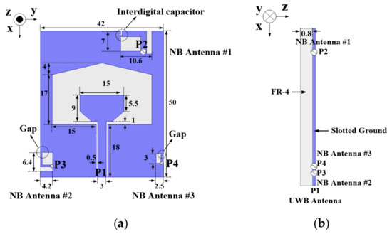
Figure 1.
Geometry of the proposed antenna: (a) top view (b) side view (all dimensions are in mm). NB: narrowband; UWB: ultra-wideband.
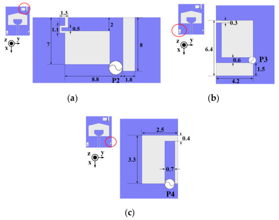
Figure 2.
Geometry of the proposed NB antennas: (a) NB Antenna #1, (b) NB Antenna #2 and (c) NB Antenna #3 (all dimensions are in mm).
3. Antenna Analysis
3.1. Operating Modes of the Proposed Design
The proposed antenna can operate in eight different modes, including a UWB spectrum sensing mode and seven different communication modes, as shown in Table 1. In the communication modes, there are three modes for holes in a single band, three modes for holes in two bands, and one mode for holes in low (3–5 GHz), mid (5–8 GHz) and high (8–11 GHz) frequency bands. Eight operative modes of the proposed antenna are analyzed in the following sections.

Table 1.
Communication modes depending on the on–off status of the ports.
3.2. UWB Sensing Mode
The proposed UWB antenna consists of a wide-slot and a CPW-fed monopole. The wideband characteristics are obtained by utilizing capacitive coupling between the two structures [32]. The circumference of the wide-slot is 1 at 3.1 GHz. Figure 3 shows the simulated reflection coefficient characteristics of the proposed UWB antenna. The −10 dB reflection coefficient bandwidth is from 2.7 GHz to 12 GHz. To understand the operating principle, the surface current distributions of the UWB antenna are analyzed in Figure 4. The frequencies used for the analysis of the proposed antenna in low, mid, and high frequency bands are 3.1 GHz (first resonant frequency of the UWB antenna), 6.52 GHz (second resonant frequency of the NB Antenna #2), and 9.5 GHz (resonant frequency of the NB Antenna #3). The current is excited vertically in all three frequencies within the UWB band. In Figure 4a, 1 resonance is generated at 3.1 GHz. On the other hand, in mid and high-frequency bands (6.52 GHz and 9.5 GHz), the wide-slot is excited by higher order modes and the surface current on the slot becomes weaker.
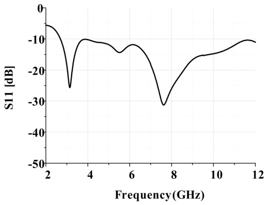
Figure 3.
Simulated reflection coefficients of the proposed UWB antenna.
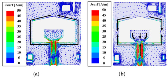
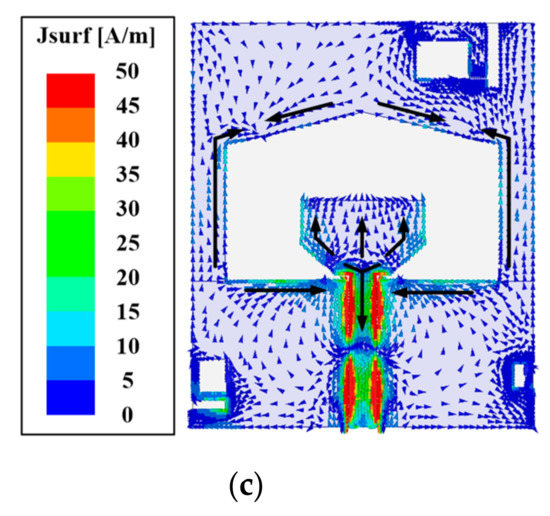
Figure 4.
Simulated surface current distributions of the proposed antenna for spectrum sensing mode (P1 ON): (a) low frequency at 3.1 GHz, (b) mid frequency at 6.52 GHz, and (c) high frequency at 9.5 GHz.
3.3. Single Communication Mode
3.3.1. Communication Mode #1
NB Antenna #1, located at the upper right corner of the ground, is responsible for communication in the low-frequency band (Communication Mode #1). Figure 5 depicts the simulated S-parameters of the proposed antenna in Mode #1. NB Antenna #1 has a wide bandwidth, from 2.96 GHz to 5.38 GHz (fractional bandwidth: 58.8%), which is achieved by combining resonances at 3.5 GHz (first resonance) and 4.9 GHz (second resonance). In addition, the isolation between the UWB antenna and NB Antenna #1 is greater than 17.3 dB, with a peak value of 39.4 dB at 2.96 GHz.
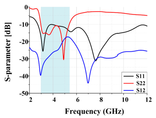
Figure 5.
Simulated S-parameters of the proposed antennas for communication mode #1.
To understand the operating principle of NB antenna #1, the surface current distributions at resonant frequencies are analyzed in Figure 6. As shown, the loop-type current is distributed on NB Antenna #1 at the first resonance frequency of 3.5 GHz from Figure 6a. In Figure 6b, it is noted that the second resonance at 4.9 GHz is excited by the U-shaped current distribution formed by the slot between the loop and left ground.
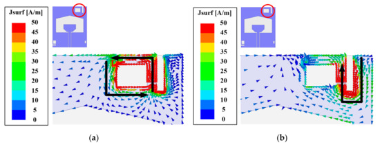
Figure 6.
Simulated surface current distributions of NB Antenna #1 (a) at 3.5 GHz and (b) at 4.9 GHz.
Because the UWB antenna is an electric dipole type, the resonances on the UWB antenna are mainly determined by the vertical length of the ground plane [30]. Due to the orthogonal current modes from the ground plane, high isolation characteristics can be achieved without applying any additional decoupling structures in this design.
To further understand the high isolation mechanism of NB Antenna #1, parametric studies for the key parameter D are analyzed in Figure 7. The parameter D represents the distance NB Antenna #1 moves down toward the wide slot. D = 0.8 mm is the maximum value to obtain the complete wide-slot UWB antenna structure. From Figure 7, it can be observed that the antenna achieves high isolation performance (greater than 17 dB) in spite of the close proximity of the UWB antenna and NB Antenna #1, without a noticeable change in the reflection coefficient characteristics. To attain optimal antenna performance, D = 0 mm is chosen as the proposed design parameter for NB Antenna #1.
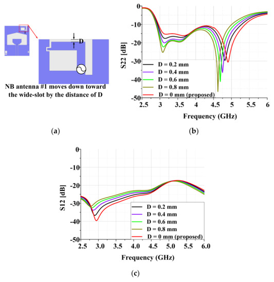
Figure 7.
Simulated S parameters for various values of D: (a) geometry of NB Antenna #1, (b) reflection coefficient of NB Antenna #1, and (c) transmission coefficient between the UWB and NB Antenna #1.
3.3.2. Communication Mode #2
Communication Mode #2 is conducted by NB Antenna #2. In Mode #2, NB Antenna #2 is used to communicate in the mid-frequency band (5–8 GHz). Figure 8 shows the S-parameter characteristics of NB Antenna #2. The −10 dB reflection coefficient bandwidth of NB Antenna #2 ranges from 5.31 GHz to 8.62 GHz (fractional bandwidth: 47.5%) with three resonant frequencies at 5.5 GHz, 6.52 GHz, and 7.65 GHz. The isolation between the UWB antenna and NB Antenna #2 is greater than 19.1 dB, with a peak value of 34 dB at 5.95 GHz. NB Antenna #2 is designed with the same form as NB Antenna #1. Due to the large separation (greater than /2) between the two input ports of the UWB antenna and NB Antenna #2, high isolation performance is maintained in the desired mid-frequency band.
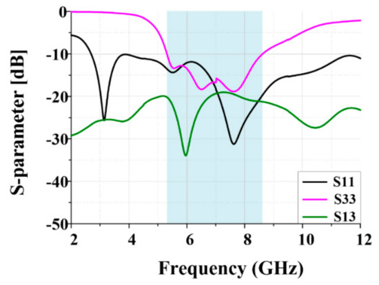
Figure 8.
Simulated S-parameters of the proposed antennas for communication mode #2.
To verify the operating principle of NB Antenna #2, current distributions of NB Antenna #2 at resonant frequencies of 5.5 GHz, 6.52 GHz, and 7.65 GHz are shown in Figure 9. As shown in Figure 9a,b, the loop type current excites the ground modes. In Figure 9a, the vertical current mode is excited on the ground at 5.5 GHz. In Figure 9b, the high order horizontal current mode is excited on the ground at 6.52 GHz. Therefore, high isolation can be obtained at 6.52 GHz. As shown in Figure 9c, the inverted C-shaped current on NB Antenna #2 excites the vertical ground mode.
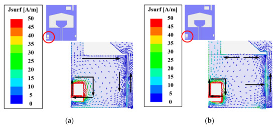
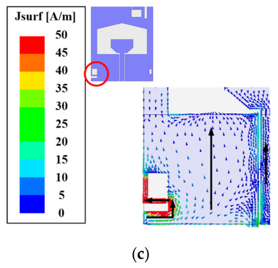
Figure 9.
Simulated surface current distributions of NB Antenna #2 at three resonant frequencies (a) at 5.5 GHz, (b) at 6.52 GHz, and (c) at 7.65 GHz.
Since the UWB antenna is orthogonal to the horizontal ground mode of NB Antenna #2 at 6.52 GHz, the isolation performance at 6.52 GHz is highest among the three resonant frequencies. However, the isolation performance over the entire mid-frequency band remains high (greater than 19 dB) due to the relatively large separation between the UWB antenna and NB Antenna #2.
3.3.3. Communication Mode #3
NB Antenna #3 operates from 8.48 GHz to 11.02 GHz (fractional bandwidth of Mode #3: 26.1%) with a resonant frequency at 9.5 GHz, as shown in Figure 10. The isolation between NB Antenna #3 and the UWB antenna is higher than 19 dB, with a peak value of 26.9 dB over the high-frequency band (8 GHz–11 GHz).
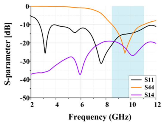
Figure 10.
Simulated S-parameters of the proposed antenna for communication mode #3.
To investigate the operating principle of NB Antenna #3, the surface current distribution at the resonant frequency of 9.5 GHz is shown in Figure 11. NB Antenna #3 operates in a loop current mode. Due to the large separation between the UWB antenna and NB Antenna #3, high isolation performance can be obtained in the high-frequency band.
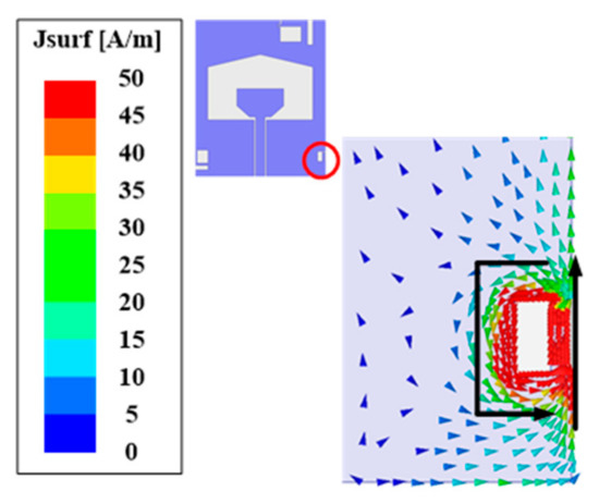
Figure 11.
Simulated surface distribution of the NB antenna at the resonant frequency of 9.5 GHz.
3.4. Multi-Communication Mode
In this section, multiple NB antenna modes, namely NB antenna modes #4 to #7, are analyzed. When multiple antennas are excited, the active S-parameters and S-parameters are different because the reflection coefficient at each port is affected by the inter-port coupling [33]. To investigate this phenomenon, the active S-parameters for multiple communication modes are compared with the S-parameters for a single communication mode. Figure 12 shows the S-parameters comparison between single communication modes and multi-communication modes. In single-mode operation, only one NB antenna is activated. On the other hand, two or more antennas are excited simultaneously in the multi-communication mode.
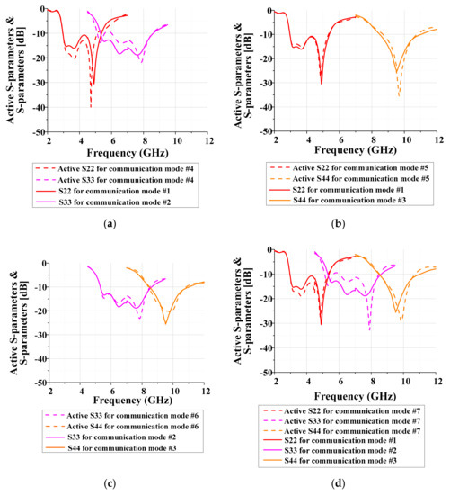
Figure 12.
Comparisons of simulated active S-parameters for multi-communication and S-parameters for single communication: (a) communication mode #4 (P2 & P3 ON), (b) communication mode #5 (P2 & P4 ON), (c) communication mode #6 (P3 & P4 ON), and (d) communication mode #7 (P2 & P3 & P4 ON).
For communication mode #4 (P2 & P3: ON), the active S-parameters for ports 2 and 3 do not agree well with those of the single mode at the same frequencies in low and mid bands, as shown in Figure 12a. As illustrated in Figure 12b, the agreement between the two modes is excellent in communication mode #5 (P2 & P4: ON) due to the relatively large distance separation in terms of wavelength in the high band. In addition to that, the currents excited on the ground plane by NB Antenna #1 and Antenna #3 are almost orthogonal to each other, as shown in Figure 6 and Figure 9. For communication mode #6, the S-parameters match well with each other both in mid and high bands, since the separation between the two antennas is long enough to minimize the coupling effect. For communication mode #7, (P2, P3 & P4: ON), there is a discrepancy in the low and mid bands, as depicted in Figure 12d. Especially, the reflection coefficient in the mid band is affected considerably by the coupling from both NB Antennas #1 and #3. This coupling effect can be alleviated by using a defected ground, a decoupling network, and (or) pattern diversity [24,25,26]. However, since the −10 dB reflection coefficient requirement is satisfied almost over entire the desired frequency band, we did not utilize such technologies.
To further investigate the S-parameter degradation of NB Antennas #2 and #3 in some frequencies under multi-communication modes, namely modes #4 and #7, the surface current distributions are analyzed and shown in Figure 13. Since the performance degradation around 5.2 GHz is evident, as shown in Figure 12a,d, the surface current distributions at 5.2 GHz are evaluated for both communication modes #4 and #7. As shown in Figure 13a, when NB Antennas #1 and #2 are activated simultaneously, currents excited along the left and upper left sides of the ground plane cause electromagnetic coupling between NB Antennas #1 and #2. In turn, the reflection coefficients deteriorate slightly. For communication mode #7 (P2, P3, & P4: ON), a similar coupling mechanism is generated between NB Antennas #1 and #2 as in the case of communication mode #4. However, since a very weak current is excited by NB Antenna #1 along the lower right side of the ground plane, as shown in Figure 13b, the effect of coupling in the reflection coefficient performance of NB Antenna #3 is minimal. The surface current distributions for communication modes #5 and #6 are not shown, since the reflection coefficient comparisons shown in Figure 12b,c are in good agreement.
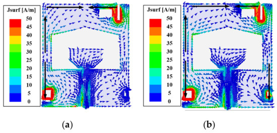
Figure 13.
Simulated surface current distributions for multi-communication mode at 5.2 GHz. (a) Communication mode #4 (P2 & P3 ON); (b) Communication mode #7 (P2 & P3 & P4 ON).
4. Experimental Results
Figure 14 shows a photograph of the fabricated antenna. Figure 15 illustrates the measured and simulated reflection coefficient characteristics of the fabricated UWB antenna. The fabricated UWB antenna satisfies a −10 dB reflection coefficient bandwidth from 2.4 GHz to 12 GHz, which is wide enough to fully cover the desired UWB spectrum.
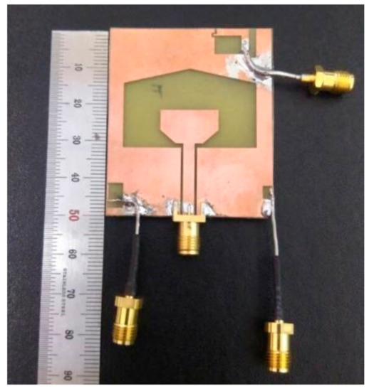
Figure 14.
Photograph of the proposed antenna.
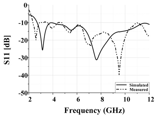
Figure 15.
Measured and simulated reflection coefficient characteristics of the fabricated UWB antenna.
The measured and simulated S-parameters of the three types of NB antenna are shown in Figure 16. NB Antenna #1 operates from 3.05 GHz to 5.35 GHz in the low-frequency band. NB Antenna #2 operates from 5.75 GHz to 9 GHz in the mid-frequency band, and NB Antenna #3 satisfies a −10 dB reflection coefficient from 9.15 GHz to 11.2 GHz in the high-frequency band. Additionally, the three NB antennas maintain a high isolation level (greater than 17 dB) over the whole operating frequency band.
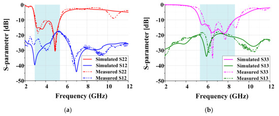
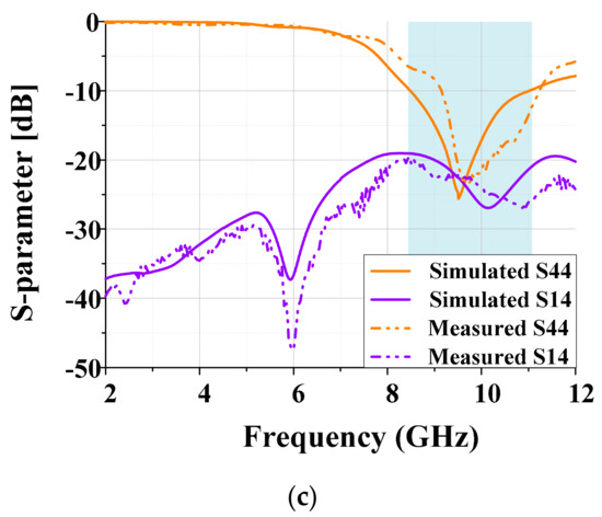
Figure 16.
Measured and simulated S-parameters of NB antennas: (a) NB Antenna #1, (b) NB Antenna #2 and (c) NB Antenna #3.
Figure 17 shows the simulated and measured radiation patterns of the fabricated UWB antenna at 3.5 GHz, 4.9 GHz, 6.52 GHz, 7.65 GHz, and 9.5 GHz. The fabricated UWB antenna has quasi-omnidirectional radiation patterns in the YZ plane.
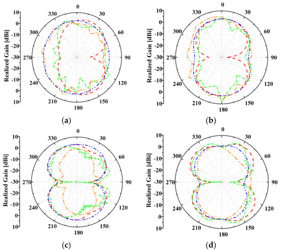
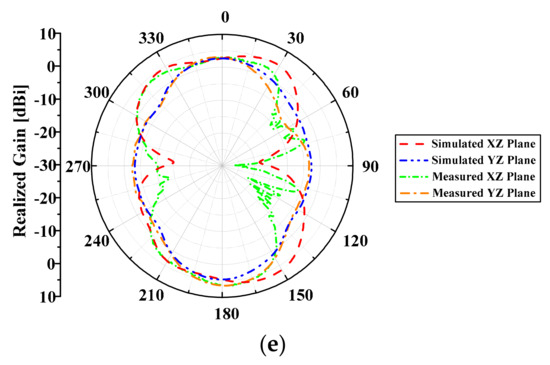
Figure 17.
Simulated and measured radiation patterns of the UWB antenna for various frequencies: (a) at 3.5 GHz; (b) at 4.9 GHz; (c) at 6.52 GHz; (d) at 7.65 GHz; € at 9.5 GHz.
Figure 18 shows the simulated and measured radiation patterns of the NB antennas at 3.5 GHz, 4.9 GHz, 6.52 GHz, 7.65 GHz, and 9.5 GHz. The NB antennas have quasi-omnidirectional radiation patterns in the YZ plane.
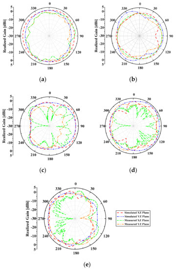
Figure 18.
Simulated and measured radiation patterns of the NB antennas for various frequencies. (a) NB Antenna #1 at 3.5 GHz; (b) NB Antenna #1 at 4.9 GHz; (c) NB Antenna #2 at 6.52 GHz; (d) NB Antenna #2 at 7.65 GHz; (e) NB Antenna #3 at 9.5 GHz.
Table 2 shows a comparison of the simulated and measured peak gains of the proposed antennas. Recognizable discrepancies exist between the simulated and measured peak gains in the mid and high frequency bands. We think that the discrepancy is due to the cable loss and effect of the feeding structure, which was not considered in the simulation.
Table 2.
The comparison of the simulated and measured peak gains of the proposed antennas at center resonant frequencies of the NB antennas.
Table 3 shows comparisons of various integrated UWB and NB antenna systems. From Table 3, it can be easily seen that the proposed antenna provides full coverage of the UWB communication band using only three NB antennas. This is attributed to the small-size broadband loop-type ground radiation antennas. This research also maintains relatively high isolation levels despite the compact ground size.
Table 3.
Comparison of various integrated UWB and NB antenna systems.
5. Conclusions
Based on the excitation switching reconfigurable mechanism, a compact four-port coplanar antenna design for CR applications is proposed in this paper. The proposed antenna combines a CPW-fed wide slot UWB antenna and three ground-coupled loop type NB antennas. The UWB antenna fully covers the UWB spectrum from 3.1 to 10.6 GHz and can detect unoccupied spectrum bands. NB Antenna #1, NB Antenna #2, and NB Antenna #3 cover the low-frequency band (3 GHz–5 GHz), mid-frequency band (5 GHz–8 GHz), and high-frequency band (8 GHz–11 GHz), respectively. As a result, only three NB antennas are required to cover the full UWB spectrum band. High isolation (greater than 17.3 dB) is maintained between the UWB antenna and the NB antennas over the entire UWB band. The realized gains of the UWB antenna and NB antennas are greater than 2.7 dBi and 1.38 dBi, respectively. Additionally, the proposed CR antenna can operate in eight modes, including a UWB spectrum sensing mode and seven communication modes which include a 5G sub-6 GHz frequency band. Finally, the proposed antenna design has increased spectrum efficiency and wide bandwidth over the entire UWB band. Therefore, the proposed antenna is a good candidate for not only CR systems but also 5G sub-6 GHz applications.
Author Contributions
The presented work was carried out in collaboration between all the authors. Y.O. wrote the paper. Y.J. participated in the conception. J.C. supervised the research.
Funding
This work was supported by a National Research Foundation of Korea (NRF) grant funded by the Korean government (MSIP) (No. 2017R1A2B4002811). This work was supported by Advanced Track for the State-of-the-art Technology of an Earth Resources Industry with an ICT Application of the Korea Institute of Energy Technology Evaluation and Planning (KETEP) granted financial resource from the Ministry of Trade, Industry & Energy, Republic of Korea (20174010201170).
Conflicts of Interest
The authors declare no conflict of interest.
References
- Cognitive Radio: UWB Integration and Related Antenna Design. Available online: https://www.intechopen.com/books/new-trends-in-technologies--control--management--computational-intelligence-and-network-systems/cognitive-radio-uwb-integration-and-related-antenna-design (accessed on 3 July 2019).
- Federal Communications Commission. Spectrum Policy Task Force; Rep. ET Docket; Federal Communications Commission: Washington, DC, USA, November 2002.
- Ojaroudi, M.; Ojaroudi, N. Ultra-Wideband Small Rectangular Slot Antenna with Variable Band-Stop Function. IEEE Trans. Antennas Propag. 2014, 62, 490–494. [Google Scholar] [CrossRef]
- Shakib, M.N.; Moghavvemi, M.; Mahadi, W.N.L. A low-profile patch antenna for ultrawideband application. IEEE Antennas Wirel. Propag. Lett. 2015, 14, 1790–1793. [Google Scholar] [CrossRef]
- Malekpoor, H.; Hamidkhani, M. Compact multi-band stacked circular patch antenna for wideband applications with enhanced gain. Electromagnetics 2019, 39, 241–253. [Google Scholar] [CrossRef]
- Kim, S.W.; Choi, D.Y. Implementation of Rectangular Slit-Inserted Ultra-Wideband Tapered Slot Antenna. SpringerPlus 2016, 5, 1387. [Google Scholar] [CrossRef] [PubMed][Green Version]
- Tseng, V.; Chang, C.Y. Linear Tapered Slot Antenna for Ultra-Wideband Radar Sensor: Design Consideration and Recommendation. Sensors 2019, 19, 1212. [Google Scholar] [CrossRef] [PubMed]
- Deng, J.; Hou, S.; Zhao, L.; Guo, L. Wideband-to-Narrowband Tunable Monopole Antenna with Integrated Bandpass Filters for UWB/WLAN Applications. IEEE Antennas Wirel. Propag. Lett. 2017, 16, 2734–2737. [Google Scholar] [CrossRef]
- Mosallaei, H.; Sarabandi, K. Antenna miniaturization and bandwidth enhancement using a reactive impedance substrate. IEEE Trans. Antennas Propag. 2004, 52, 2403–2414. [Google Scholar] [CrossRef]
- Yao, J.; Mbanya, T.F.; Jain, A.; Tjuatja, S.; Huang, H. Far-Field Interrogation of Microstrip Patch Antenna for Temperature Sensing Without Electronics. IEEE Sens. J. 2016, 16, 7053–7060. [Google Scholar] [CrossRef]
- Li, L.W.; Li, Y.N.; Yeo, T.S.; Mosing, J.R.; Martin, O.J.F. A Broadband and high-gain metamaterial microstrip antenna. Appl. Phys. Lett. 2010, 96, 164101. [Google Scholar] [CrossRef]
- Zhang, H.T.; Luo, G.Q.; Yuan, B.; Zhang, X.H. A Novel Ultra-Wideband Metamaterial Antenna Using Chessboard-Shaped Patch. Microw. Opt. Technol. Lett. 2016, 58, 3008–3012. [Google Scholar] [CrossRef]
- Simons, R.N. Conventional Coplanar Waveguide. Coplanar Waveguide Circuits, Components, and Systems, 1st ed.; Chang, K., Ed.; Wiley: New York, NY, USA, 2001; Volume 1, pp. 1–2. [Google Scholar]
- Lin, Y.F.; Chang, M.J.; Chen, H.M.; Huang, S.T. Theoretical study of ground radiation tag antenna with Tunable open-slot exciter. Int. J. Microw. Wirel. Techol. 2017, 9, 945–952. [Google Scholar] [CrossRef]
- Liu, Y.; Lee, J.; Kim, H.H.; Kim, H. Ground radiation method using slot with coupling capacitors. Electron. Lett. 2013, 49, 447–448. [Google Scholar] [CrossRef]
- Tawk, Y.; Costantine, J.; Christodoulou, C.G. A rotatable reconfigurable antenna for cognitive radio applications. In Proceedings of the IEEE Radio and Wireless Symposium, Phoenix, AZ, USA, 16–19 January 2011; pp. 158–161. [Google Scholar]
- Ebrahimi, E.; Kelly, J.R. Integrated Wide-Narrowband Antenna for Multi-Standard Radio. IEEE Trans. Antennas Propag. 2011, 59, 2628–2635. [Google Scholar] [CrossRef]
- Tawk, Y.; Costantine, J.; Christodoulou, C.G. Demonstration of a Cognitive Radio Front End Using an Optically Pumped Reconfigurable Antenna System (OPRAS). IEEE Trans. Antennas Propag. 2012, 60, 1075–1083. [Google Scholar] [CrossRef]
- Anvesh Kumar, N.; Gandhi, A.S. A compact novel three-port integrated wide and narrow band antennas system for cognitive radio applications. Int. J. Antennas Propag. 2016, 2016, 2829357. [Google Scholar]
- Anvesh Kumar, N.; Gandhi, A.S. A Five-Port Integrated UWB and Narrowband Antennas System Design for CR Applications. IEEE Trans. Antennas Propag. 2018, 66, 1669–1676. [Google Scholar]
- Jin, G.; Liao, H.; Liu, D. A dual-port frequency reconfigurable antenna for cognitive radio applications. In Proceedings of the IEEE International Conference on Computational Electromagnetics, Guangzhou, China, 23–25 February 2016. [Google Scholar]
- Pahadsingh, S.; Sahu, S. A two port UWB-dual narrowband antenna for cognitive radios. Microw. Opt. Technol. Lett. 2019, 58, 1973–1978. [Google Scholar] [CrossRef]
- Anvesh Kumar, N.; Gandhi, A.S. A Survey on Planar Antenna Designs for Cognitive Radio Applications. Wirel. Pers. Commun. 2018, 98, 541–569. [Google Scholar]
- Shoaib, S.; Shoaib, I.; Shoaib, N.; Chen, X.; Parini, C.G. Design and Performance Study of a Dual-Element Multiband Printed Monopole Antenna Array for MIMO Terminals. IEEE Antennas Wirel. Propag. 2014, 13, 329–332. [Google Scholar] [CrossRef]
- Wu, C.; Chiu, C.; Ma, T. Very Compact Fully Lumped Decoupling Network for a Coupled Two-Element Array. IEEE Antennas Wirel. Propag. 2016, 15, 158–161. [Google Scholar] [CrossRef]
- Alsath, M.G.N.; Kanagasabai, M. Compact Monopole Antenna for Automotive Communications. IEEE Trans. Antennas Propag. 2015, 63, 4204–4208. [Google Scholar] [CrossRef]
- Vainikainen, P.; Ollikainen, J.; Kivekas, O.; Kelander, K. Resonator-based analysis of the combination of mobile handset antenna and chassis. IEEE Trans. Antennas Propag. 2002, 50, 1433–1444. [Google Scholar] [CrossRef]
- Zhao, X.; Yeo, S.P.; Ong, L.C. Planar UWB MIMO Antenna with Pattern Diversity and Isolation Improvement for Mobile Platform Based on the Theory of Characteristic Modes. IEEE Trans. Antennas Propag. 2018, 66, 420–425. [Google Scholar] [CrossRef]
- Li, H.; Lau, B.K.; Ying, Z.; He, S. Decoupling of Multiple Antennas in Terminals with Chassis Excitation Using Polarization Diversity, Angle Diversity and Current Control. IEEE Trans. Antennas Propag. 2012, 60, 5947–5957. [Google Scholar] [CrossRef]
- Jin, Y.; Ko, M.; O, Y.; Choi, J. A planar UWB MIMO antenna with gain enhancement and isolation improvement for the 5G Mobile platform. Microw. Opt. Technol. Lett. 2019, 61, 990–998. [Google Scholar] [CrossRef]
- Chen, J.; Berg, M.; Somero, V.; Pärssinen, A. A Multiple Antenna System Design for Wearable Device Using Theory of Characteristic Mode. In Proceedings of the 12th European Conference on Antennas and Propagation, London, UK, 9–13 April 2018. [Google Scholar]
- Kumar, R.; Naidu, P.V.; Kamble, V. Design of asymmetric slot antenna with meandered narrow rectangular slit for dual band applications. Prog. Electromagn. Res. 2014, 60, 111–123. [Google Scholar] [CrossRef]
- Zhang, C.; Lai, Q.; Gao, C. Measurement of Active S-Parameters on Array Antenna Using Directional Couplers. In Proceedings of the IEEE Asia Pacific Microwave Conference, Kuala Lumpar, Malaysia, 13–16 November 2017. [Google Scholar]
© 2019 by the authors. Licensee MDPI, Basel, Switzerland. This article is an open access article distributed under the terms and conditions of the Creative Commons Attribution (CC BY) license (http://creativecommons.org/licenses/by/4.0/).