Article

Effect of Harsh Conditions on the Tensile Behaviour of Lap-Spliced Carbon Fiber Textile-Reinforced Mortar (TRM) with Different Surface Treatment Methods

School of Architecture, Soongsil University, 369 Sangdo-ro, Dongjak-gu, Seoul 06978, Korea
*
Author to whom correspondence should be addressed.
Appl. Sci. 2019, 9(15), 3087; https://doi.org/10.3390/app9153087
Submission received: 20 June 2019 / Revised: 18 July 2019 / Accepted: 27 July 2019 / Published: 31 July 2019

Abstract

:
In the present study, the effect of harsh conditions on the tensile behavior of lap-spliced carbon fiber textile-reinforced mortar (TRM) with different surface treatment methods was investigated through the direct tensile test. The TRM coupons were exposed to three different harsh conditions: a chloride environment of 3.5 wt.% sodium chloride, a high temperature and humidity environment (50 °C and 95% relative humidity), and sustained load of 30% of the tensile strength during 60 days. In addition, two different surface treatment methods of the lap-spliced region of TRM coupons were used: carbon fiber textile impregnated by epoxy resin, and carbon fiber textile covered with aluminum oxide (Al2O3) powder after epoxy resin impregnation. The tensile characteristics of TRM coupons were investigated in terms of the cracking strength, ultimate strength, initial stiffness, and ultimate strain, to evaluate the influence of different surface treatment methods on the tensile behaviors of TRM coupons after exposure to various types of harsh conditions. Additionally, the test results were compared to the previous test results of TRM coupons that were not subjected to harsh conditions.

1. Introduction

Fiber-reinforced polymer (FRP) methods have been widely applied in civil engineering due to their various advantages: no difficulty in the application with various shapes, high speed in the installation, high capacity of corrosion resistance, lightweight, and good mechanical properties [1,2,3,4,5]. However, the disadvantages of FRP methods could include their low capacity of fire resistance, poor behavior at high temperatures, low capacity of vapor permeation, low compatibility between resins and the structural surface (e.g., concrete or masonry), and irreversibility of the application (that is, the capability of undoing the repair, without harming the original structure) [6,7,8,9]. Nowadays, the use of composite materials, including textile-reinforced mortar (TRM), for the repair and strengthening of concrete and masonry structures has become a common technique in the civil engineering community. TRM composites comprise a cement-based matrix reinforced with various types of fiber textile (e.g., carbon fiber textile, glass fiber textile). TRM composites have become an alternative solution to conventional techniques, such as steel plates, reinforced concrete (RC) overlay, post-tensioning, and even fiber-reinforced polymer systems. Therefore, TRM composites could be widely applied to strengthen, repair, and retrofit existing concrete and masonry structures [10,11,12,13,14,15,16].
To understand the mechanical characteristics of the TRM composite, many studies have been carried out on the bond properties of TRM used in concrete structures [17,18,19,20,21,22,23]. The fabric–mortar interface behavior is essential to the stress transfer between the fiber filaments within a yarn, and between the yarns and the mortar matrix. Various surface treatment methods were applied on the surface of TRM coupons using epoxy impregnation [24,25,26,27] or sand coating after epoxy impregnation [27,28,29] of the textile or polymer coating of single filament jute fibers and yarns [30], which could significantly enhance the mechanical characteristics of the TRM coupons (e.g., bond strength and stiffness). These techniques might result in an improvement of the mechanical properties of the TRM composite. In addition, the surface treatment could change the failure mode of the TRM composites from the slippage of carbon fiber mesh inside the mortar matrix to carbon fibers rupture [27].
A limited number of studies were performed to investigate the effect of harsh environments on the tensile behavior of TRM composites. One of the important aspects of TRM composites that requires a lot of attention is their ability to withstand harsh conditions, such as seawater, alkali and acid, hot-wet/dry environments, freeze and thaw cycles, etc. Nobili et al. [31] and Mecelli et al. [32] showed that aggressive environments, especially seawater and alkaline environments, may reduce the tensile characteristics of carbon fiber-reinforced cementitious matrix composites. Therefore, more experimental studies are necessary to gain a better knowledge of the tensile behavior of TRM composites subjected to various types of harsh conditions.
In this research, the effect of harsh conditions on the tensile behavior of TRM coupons was studied via direct tensile tests, in accordance with ACI 549.4R-13 [33]. The TRM coupons consisted of an aluminum cement-based mortar used as a binder, reinforced with a lap-spliced carbon fiber textile. The TRM coupons were subjected to three different harsh conditions: a chloride environment, a high temperature and humidity environment, and a sustained load. Moreover, the effect of two surface treatment methods at the lap-spliced region of the textile was investigated: epoxy impregnation, and aluminum oxide (Al2O3) powder coating after epoxy impregnation of carbon fiber textile. The direct tensile test results of TRM coupons were investigated in terms of cracking strength, ultimate strength, initial stiffness, and ultimate strain, to evaluate the effect of different surface treatment methods on the tensile behaviors of TRM coupons subjected to harsh conditions.

2. Materials and Methods

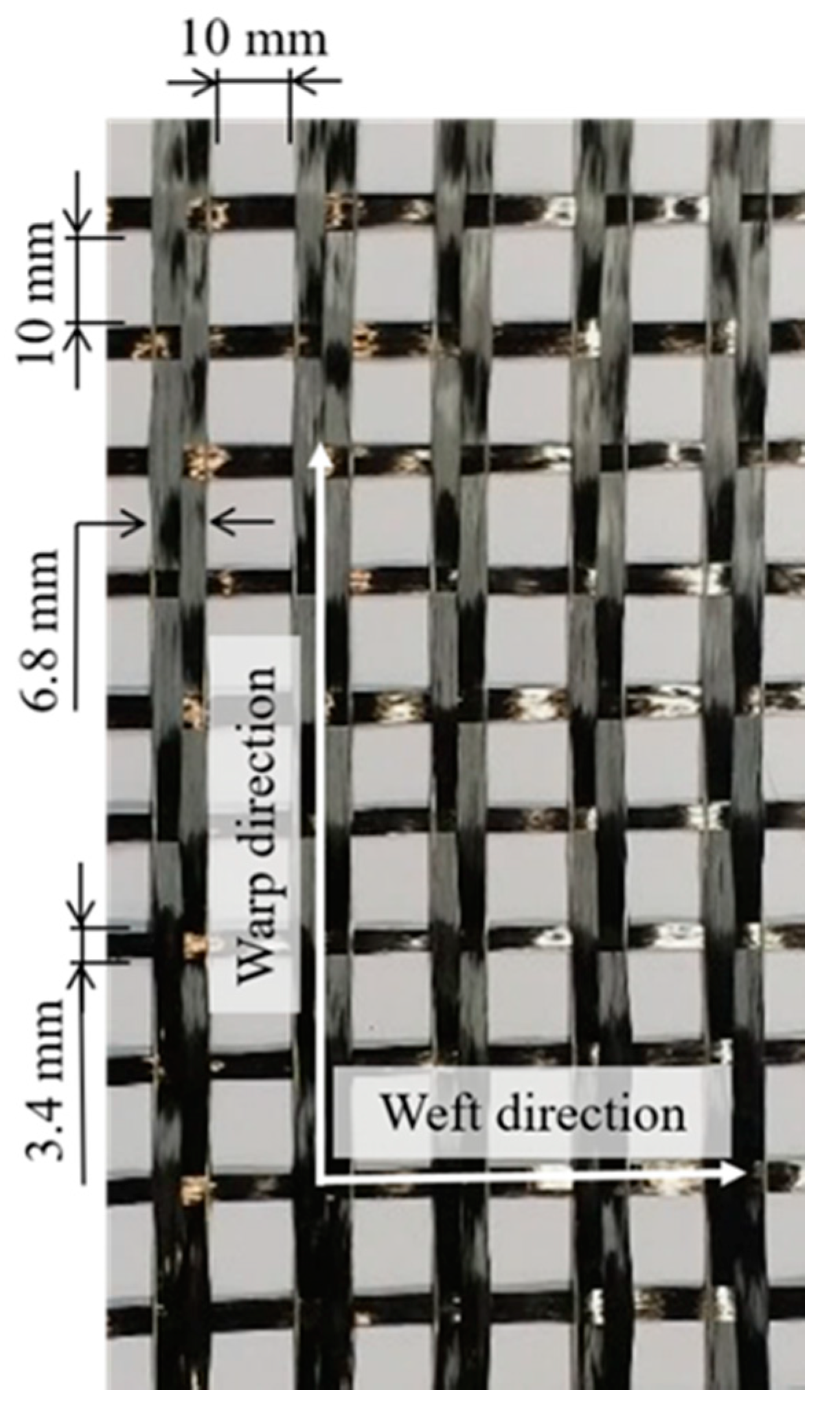
2.1. Material Properties
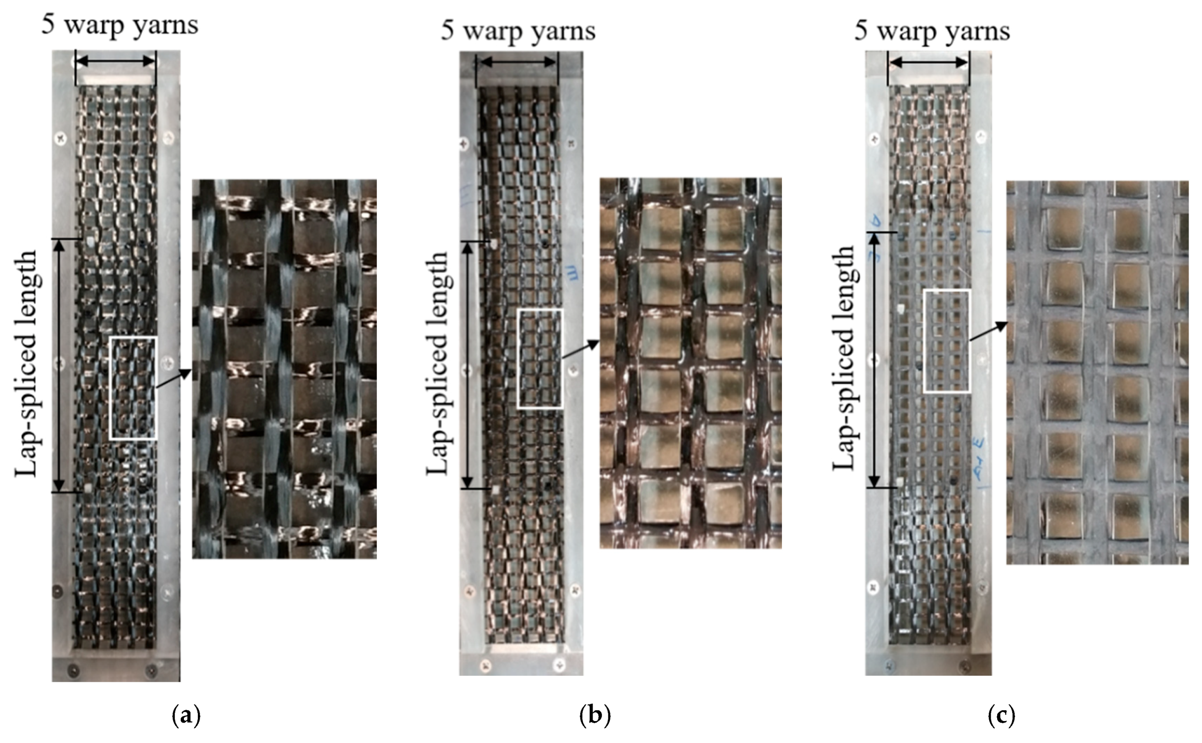
In this study, the textile-reinforced mortar (TRM) composite materials were composed of alumina cement-based mortar reinforced with carbon fiber textile. Figure 1 shows the geometrical characteristics of the carbon fiber textile utilized in this experiment as a textile reinforcement. According to the manufacturer, each warp yarn of the carbon fiber textile had an approximate width of 6.8 mm and an approximate thickness of 0.35 mm and was composed of 12,000 carbon filaments with filament diameters of 7 μm (Toray T700-12k). In addition, the carbon fiber textile had an average tensile strength and elastic modulus of 4300 MPa and 240 GPa, respectively.
The alumina cement-based mortar used as a binder in this study has high compressive strength, and shows the rapid development of compressive strength, compared to that of Portland cement mortar [34]. Additionally, alumina cement-based mortar has excellent thermal resistance and good capacity of fluidity. A type of granular sand with a granulation ratio of 2.4 was used for the mortar mixture. The mix proportion of the mortar mixture was prepared using a ratio of 1:2 for alumina cement and granular sand, along with a water–cement ratio of 0.45. The average compressive strength of mortar was 70.2 MPa at the 28th day of curing after casting, and tested as specified by Korean test standard KS L 5105 [35].

2.2. Coupon Details

The details of the TRM coupons fabricated in the laboratory are presented in Figure 2 and Table 1. All TRM coupons were a rectangular prism with dimensions 450 mm × 80 mm × 30 mm. The total length of the TRM coupons was 450 mm, including two clamping regions, each of length 115 mm, two transition zones of length 10 mm, and the central zone with a length of 200 mm.
The lap-spliced length of carbon fiber textile was chosen based on the study by Donnini et al. [36], and was equal to the length of the central zone (200 mm). It was located at the central part of the TRM coupons as the test region. The lap-spliced carbon textile as a reinforcement of the TRM composite was fabricated in the laboratory by two separated pieces of carbon fiber mesh, by means of these overlapping each other to the required length (Figure 2). The weft yarns at the lap-spliced region were fixed by cable ties, and kept straight by the edges of the mold during the casting of the TRM coupons, to ensure that during the loading process, the carbon fiber yarns could properly resist the tensile stresses (Figure 3). As a consequence, there were five warp yarns along the length of the central region of the TRM coupons, and the number of carbon fiber filaments of each warp yarn of the textile reinforcement was approximately 24,000, as shown in Figure 3. In addition, carbon fiber reinforced polymer (CFRP) tabs with a thickness of 2 mm were adhered at the clamping regions by means of epoxy resin (Figure 2), to avoid any damage within the gripping areas, and to ensure an effective force transfer from the universal testing machine.

2.3. Test Parameters

Two different surface treatment methods at the lap-spliced region of carbon fiber textile were used and tested: carbon fiber textile impregnated by epoxy (Figure 3b and Figure 4b), and carbon fiber textile covered with aluminum oxide (Al2O3) powder after epoxy impregnation (Figure 3c and Figure 4c). The purpose of the surface treatment was to avoid slippage at the lap-spliced region of the carbon fiber textile. Furthermore, the surface treatment using epoxy was able to completely penetrate between the carbon filaments that constitute carbon fiber yarns, which enhanced the mechanical bond strength at the fabric–mortar interface and affected the tensile behavior of the TRM composite in harsh conditions.
For the first surface treatment method (Figure 3b and Figure 4b), approximately 60 g of epoxy resin was used to fully impregnate the carbon fiber filaments within the lap-spliced region of the textile reinforcement. For the second surface treatment method (Figure 3c and Figure 4b), at the lap-spliced region of the textile reinforcement, the carbon fiber filaments were also completely impregnated with epoxy resin (60 g). Then, the carbon fiber textile was covered with aluminum oxide (Al2O3) powder with a diameter of 250 μm by using a high speed-spraying gun one day after epoxy impregnation [37,38]. The surface treatments were performed on both sides of the carbon fiber textile to ensure uniformity. The surface treatment methods were applied according to Truong et al. [39].

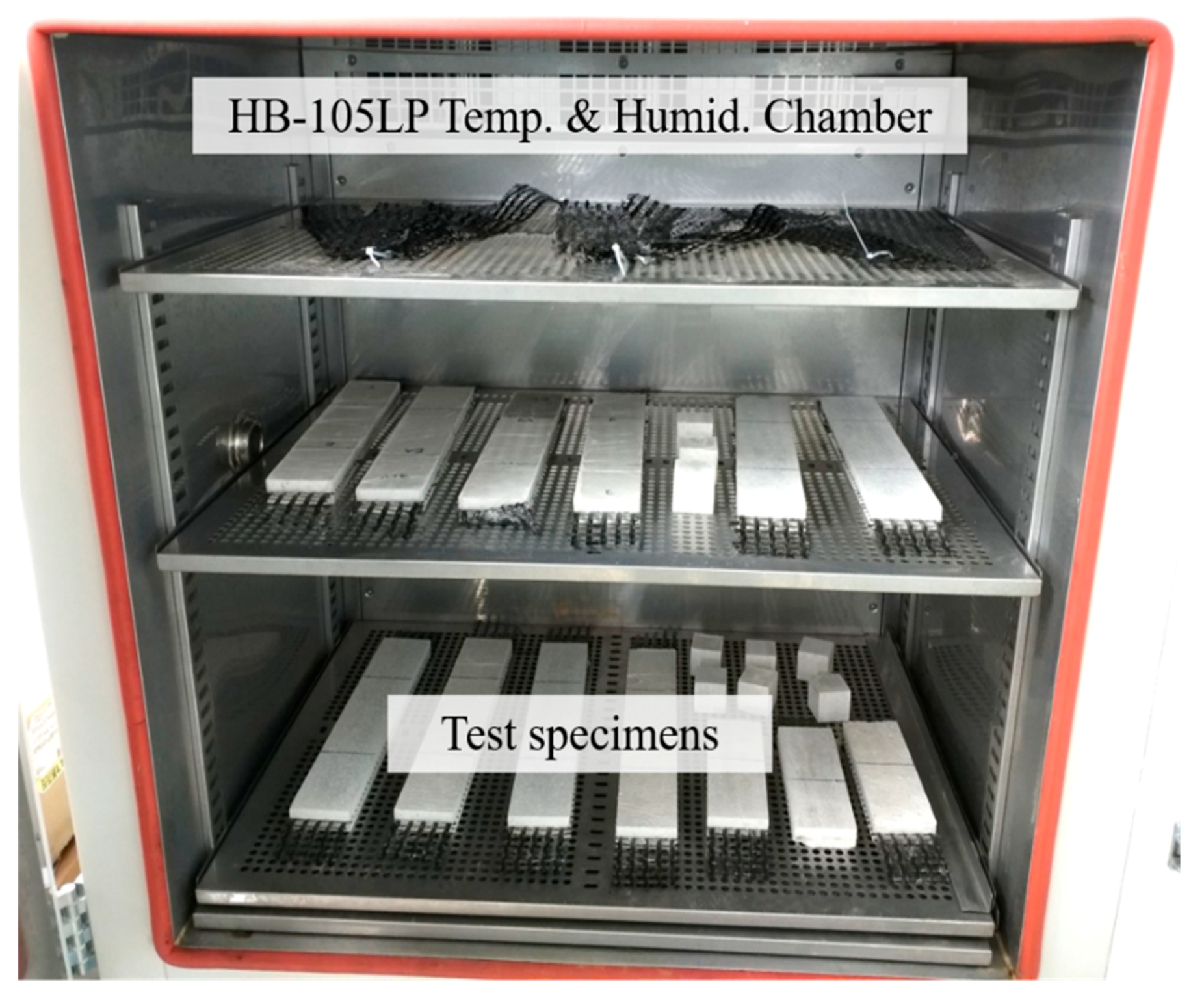
2.4. Test Environments

In this study, the TRM coupons were subjected to three different harsh conditions: chloride environment, high temperature and humidity environment, and sustained load.
For the first test series, the TRM coupons were demolded one day after casting, and then cured for 27 more days in the laboratory condition (11 ± 2 °C and 45% relative humidity), before being subjected to the chloride environment. Considering the ocean’s seawater average salinity [40], a 3.5 wt.% sodium chloride (NaCl) distilled water solution was used (Figure 5). The TRM coupons were cured for 60 days in such chemical conditions. The TRM coupons were taken out of the sodium chloride solution three days prior to the direct tensile test.
For the second test series, the TRM coupons were prepared in a similar manner to the first test series. However, to create a high temperature and humidity environment, the TRM coupons were stored at a constant temperature of 50 °C and relative humidity of 95% in a chamber for 60 days (Figure 6). The TRM coupons were then taken out of the chamber two days prior to the fixing of the CFRP tabs onto the ends of the TRM coupons. Then, the direct tensile test was performed one day later.
For the last test series, the TRM coupons were demolded one day after casting, and then adhered by CFRP tabs onto the ends. Next, the TRM coupons were cured for six more days in laboratory conditions, before being subjected to a sustained load (2.5 kN), as shown in Figure 7. The sustained load corresponded to 30% of the tensile strength at the seven-day aging. The last series was performed in the laboratory with the same conditions as those of the first two series. The TRM coupons were subjected to a sustained load for 60 days, and then the direct tensile test was performed.

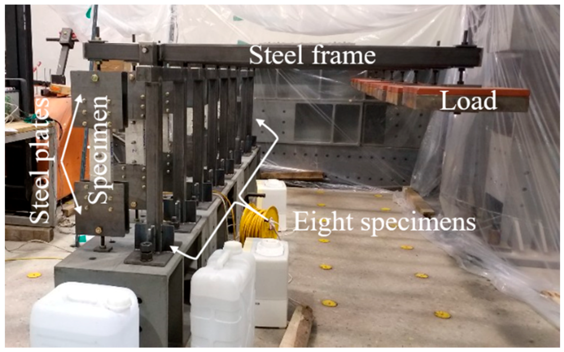
2.5. Test Setup and Instrumentation

Figure 8 shows the experimental setup of the direct tensile test for the TRM coupons. The steel plates were utilized to clamp the gripping regions of the TRM coupons and fixed by steel bolts. The clamping force induced during fixing the steel plates may have caused a high compressive force to be acting on the gripping area of the TRM coupons. Therefore, to avoid any damage within the clamping areas, and to ensure an effective force transfer from the universal testing machine, carbon fiber reinforced polymer (CFRP) tabs with a thickness of 2 mm were utilized to strengthen the gripping regions of the TRM coupons (Figure 8a). The slippage phenomenon may have occurred at the interface between the CFRP tabs and the steel plates. Hence, the surface of the steel plates was roughened to increase the friction between them. Furthermore, the non-alignment of the TRM coupons and the steel plates may have triggered a bending moment during the tensile test. Thus, a steel bar which could rotate freely around a hinge (Figure 8a) was used to connect the TRM coupons with a testing machine. This clamping method was also used in the studies of Truong et al. [39] and Kim et al. [41]. To perform the tensile tests, a universal testing machine (UTM) with a loading capacity of 1000 kN was utilized. The tensile test was performed according to ASTM D3039, with the applied load under displacement control at 0.5 mm/min [42].
To measure the tensile deformation, two linear variable displacement transformers (LVDT) were fixed at both sides along the longitudinal direction of the TRM coupons by means of the steel frames. Thus, the tensile strain of the TRM coupons was calculated as the average values obtained from LVDTs divided by the length of the central zone (180 mm).

3. Test Results and Discussions

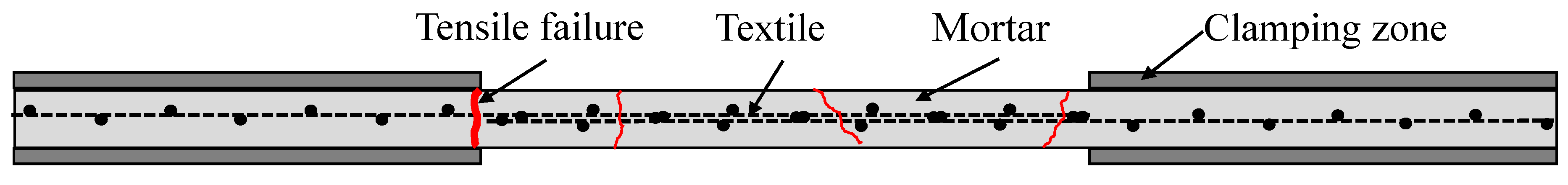
3.1. Crack Pattern and Failure Mode

Leone et al. [43] showed three different failure modes that were observed in their study during the uniaxial tensile test of fiber-reinforced cementitious matrix coupons. The first failure mode indicates the failure at the transition zone near the anchorage zone. This phenomenon is mainly due to the fact that the compressive action of the clamping force and the applied tensile load occurred simultaneously at the gripping zone. The second failure mode is related to the rupture of warp carbon fiber yarns due to the failure of the mortar matrix. The last failure mode is related to the crack of the mortar matrix, triggering slippage of carbon fiber yarns at the clamping area.
Figure 9 and Figure 10 show the typical crack patterns and failure modes observed for each series in this study. The results observed from all the TRM coupons exhibit the same failure mode, corresponding to the failure at the transition zone, as described in Figure 10. Meanwhile, the phenomena of the carbon fibers rupture and the carbon fibers slippage were not observed. During the tensile test, cracks appeared at the middle part of the TRM coupons (at the lap-spliced carbon fiber textile zone). Then, more cracks appeared near the transition zone, and continued to widen, until failure. According to Leone et al. [43], this failure mode occurs due to the fact that the compressive action of the clamping force and the applied tensile load occurred simultaneously in the gripping zone. This failure mode is desirable because it indicates the lap-spliced region is strong enough.

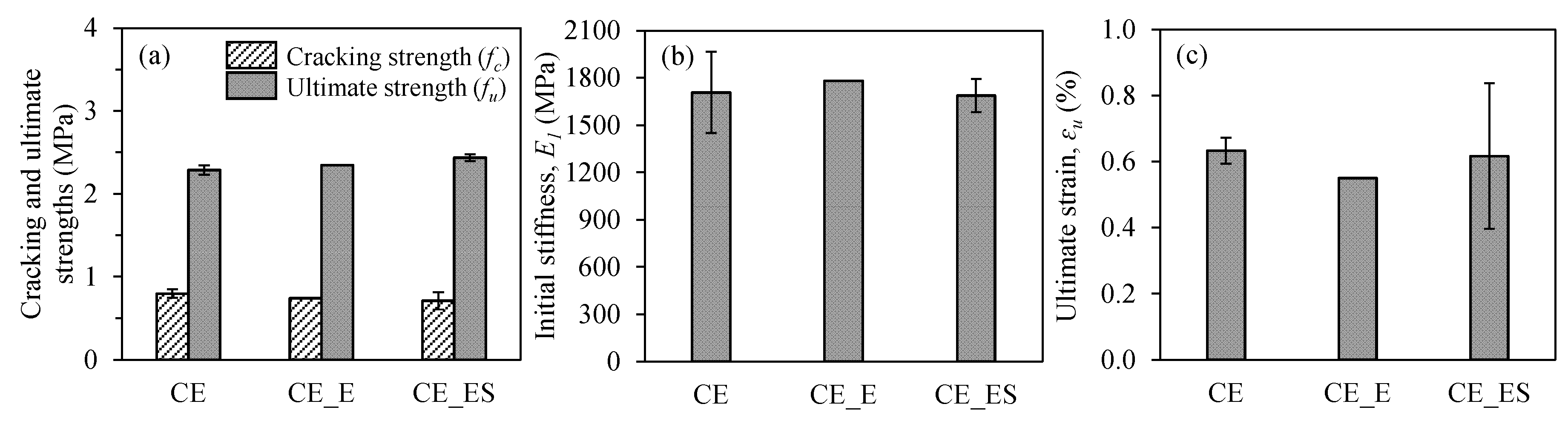
3.2. Effect of Chloride Environment

The tensile test results of TRM coupons were analyzed based on ACI 549.4R-13 [33]. The idealized stress–strain curve includes the initial segment as the uncracked stage, and the second segment as the cracked stage, which is distinguished by the significant stiffness change (transition point), as shown in Figure 11. The initial linear segment of the curve corresponds to the TRM uncracked linear behavior, and it is presented by the cracking tensile strength ( f c ) , cracking tensile strain ( ε c ) , and tensile modulus ( E 1 ) of elasticity of the uncracked coupons. In the first stage, the elastic modulus is governed by the mechanical characteristics of the mortar and carbon fiber textile based on the perfect bond at the interfaces. The second linear segment, which corresponds to the TRM cracked linear behavior, is presented by the ultimate tensile strength ( f u ) , ultimate tensile strain ( ε u ) , and tensile modulus ( E 2 ) of elasticity of the uncracked coupons.
In this study, tensile stress ( σ ) was defined as the applied load (N) divided by the cross-section area ( A s ) of the TRM coupons (80 mm × 30 mm) [39]:
The uncracked tensile modulus of elasticity was calculated for the first linear segment as:
E 1 = Δ σ / Δ ε ,
where Δ σ is the difference in tensile stress at the point where 60% of the cracking strength (MPa) is applied and Δ ε is the corresponding difference in tensile strain (see point A in Figure 11).
The cracked tensile modulus of elasticity was calculated for the second segment [33] as:
E 2 = Δ f / Δ ε = ( 0.9 f u 0.6 f u ) / ( ε 0.9 f u ε 0.6 f u ) ,
where ε 0.9 f u and ε 0.6 f u are the strains at a tensile stress level, equal to 0.9 f u and 0.6 f u , respectively (see points B and C in Figure 11). This is due to the fact that the mechanical characteristics of carbon fiber mesh mainly govern the elastic modulus in the second stage.
The first test series, which included the coupons CE, CE_E, and CE_ES, were prepared to investigate the effect of chloride environment on the tensile behavior of TRM coupons. The coupons CE mean the TRM coupons without surface treatment, subjected to a 3.5 wt.% chloride environment. The coupons CE_E and CE_ES mean the TRM coupons with epoxy impregnation, and with sand coating after epoxy impregnation, respectively.
Figure 12 shows the stress–strain relationship of the first test series with different surface treatment methods in the chloride environment. In the uncracked stage, the stress–strain relationship of the TRM coupons showed a linear elastic curve with a high slope by the combined working of both the mortar matrix and carbon fiber textile. After that, at around 0.75 MPa of tensile stress, the first cracks appeared in the middle of the TRM coupons, then more cracks appeared near the transition zone, and these cracks continued to widen, until failure (Figure 9a). Figure 13 compares the average values of initial stiffness, ultimate strain, cracking tensile strength, and peak tensile strength between TRM coupons with different surface treatments. There was no significant difference in most of the tensile behavioral characteristics, regardless of the surface treatment (Figure 13a and Table 2). However, the ultimate strains of the surface-treated TRM coupons decreased, in particular, the CE_E coupons showed a decrease of 13.09% compared to that of the CE coupons. The chloride environment might negatively affect the interfacial bonding once the chloride solution penetrates the interface made of epoxy and coating with aluminum oxide powder. The CE_E coupons showed longitudinal cracks that appeared during the tensile test (Figure 9a), during which cracking is expected to be related to bond deterioration.
Additionally, the results of TRM coupons in this series were compared to the previous test results of TRM coupons [39], with slightly different amounts and details of carbon fiber without exposure to the chloride environment. The reference TRM coupons in the previous study were Com, Com_E, and Com_ES series; the coupons Com, Com_E, and Com_ES mean the comparative coupons without surface treatment, the comparative coupons with epoxy impregnation, and the comparative coupons with sand coating after epoxy impregnation, respectively. Figure 14 presents the previous test results of the TRM coupons under sound conditions. Figure 12a and Figure 14a show that the CE and Com coupons without surface treatment revealed a significant difference in stiffness. In addition, those TRM coupons showed approximately 20% strength and 30% deformability differences. The initial stiffness and ultimate tensile strength of the CE series under chloride environment were decreased by 25–50% and 50%, respectively, compared to those of the Com series under sound conditions. This is because the chloride ion could penetrate inside the mortar and weaken the properties of the textile and the interfaces between textile and epoxy. Donnini [44] also showed that the tensile strength of glass yarns immersed in saline solution could be decreased by 40%, compared to that of controlled glass yarns. Moreover, Donnini indicated that the surface treatment using the polyvinyl alcohol (PVA) seems to be unable to protect the fiber textile reinforcement from a chloride environment, based on Scanning Electron Microscope (SEM) analysis on the cross-section of treated fiber textiles.
Note that those CE coupons slightly differ from the Com coupons in the carbon fiber amount and details, but the main difference is the chloride environment. When comparing three previous TRM coupons (Com series), they showed a significant change in strength and deformability (Figure 14). However, in the coupons of the CE series subjected to chloride environment, such a difference was not observed (Figure 12). This indicates that the improvement of bond behavior by means of surface treatment in the Com series almost disappeared in the CE series, because of the chloride environment.

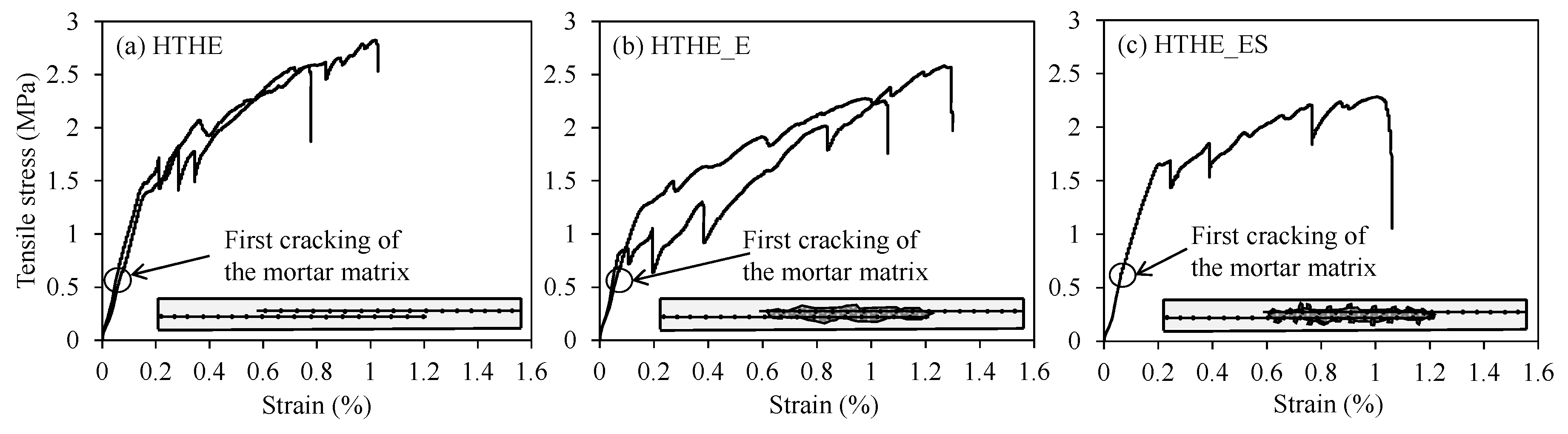
3.3. Effect of the High Temperature and Humidity Environment

The second test series that included the HTHE, HTHE_E, and HTHE_ES coupons was prepared to investigate the effect of a high temperature and humidity environment on the tensile behavior of TRM coupons. The HTHE coupons mean the TRM coupons without surface treatment subjected to the high temperature and humidity environment. Similarly, the HTHE_E and HTHE_ES coupons refer to the TRM coupons with epoxy impregnation, and the TRM coupons with sand coating after epoxy impregnation, respectively.
Figure 15 shows the stress–strain relationship of the TRM coupons with different surface treatment methods in the high temperature and humidity environment. In the uncracked stage, the TRM coupons in this series showed almost the same initial stiffness values (Figure 16a and Table 2). The crack pattern and failure mode in this series were the same as in the first series (Figure 9b). In addition, Figure 16 shows the average values of ultimate strain, cracking tensile strength, and ultimate tensile strength of TRM coupons. As presented in Figure 16a, the cracking tensile strengths were almost the same, but the ultimate tensile strengths of the HTHE_E and HTHE_ES coupons showed a slight decrease of 10.09% and 12.53% compared to that of coupons HTHE, respectively. In contrast, the ultimate strain of the HTHE_E and HTHE_ES coupons showed increases of 25.50% and 12.53%, respectively, compared to that of coupons HTHE. The results show that the high temperature and humidity environment affected the bond strength and deformability at the fabric–mortar interface. During the tensile test, longitudinal cracking at the side of the test coupons HTHE and HTHE_E was also observed (Figure 9b).
Figure 17 shows the tensile stress–strain relationship of TRM coupons subjected to the high temperature and humidity environment. Figure 17 shows that the HTHE coupons subjected to the high temperature and humidity environment revealed a significant reduction in stiffness, but a slight reduction in strength, and a slight increase in strain compared to that of the Com coupons. In addition, in the Com series, the positive effect of the surface treatment on the tensile behavior was significant, while that in the HTHE series was not significant.

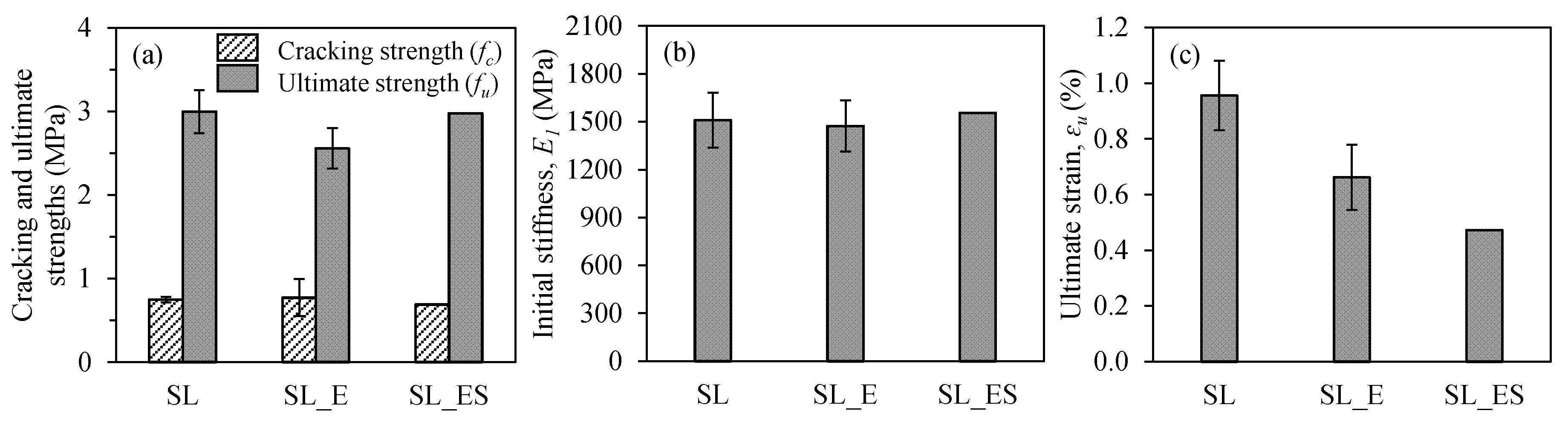
3.4. Effect of the Sustained Load

The last test series, which included the SL, SL_E, and SL_ES coupons, was prepared to investigate the effect of sustained load on the tensile behavior of TRM coupons. The SL coupons refer to the TRM coupons without surface treatment subjected to sustained load. Similarly, the SL_E and SL_ES coupons mean the TRM coupons with epoxy impregnation and the TRM coupons with sand coating after epoxy impregnation, respectively.
Figure 18 shows the stress–strain relationship of the TRM coupons with different surface treatment methods subjected to sustained load. Similar to the first two test series, the average cracking tensile strengths and the initial stiffness in this series were almost the same (Figure 19 and Table 2). Figure 19b clearly shows the effect of sustained load on the ultimate strain of TRM coupons with the different surface treatment methods. The ultimate strain of the SL_E and SL_ES coupons decreased by 30.78% and 50.59%, respectively, compared to that of the SL coupons. Meanwhile, the ultimate tensile strength in this series showed a fluctuation.
Figure 20 shows the comparison between TRM coupons with and without sustained load. The SL and Com coupons without surface treatment showed almost equal strength, but 95% deformability difference (Figure 20a). In the three previous test coupons of the Com series, the tensile strength showed a significant difference according to the surface treatment method. However, in the coupons of the SL series under sustained load, such a difference was not observed. This indicates that the improvement of tensile behavior due to surface treatment decreased because of the sustained load.

4. Conclusions

This study investigated the effect of harsh conditions on the tensile behaviors of TRM coupons. To simulate various types of harsh conditions, a chloride environment, high temperature and humidity environment, and sustained load were used. Two different details in the lap-spliced zone, including impregnation by epoxy and coating aluminum oxide powder after epoxy impregnation on carbon fiber textile, were applied to enhance the mechanical characteristics of TRM coupons. Besides this, the test results were also compared to the previous test results of TRM coupons that were not subjected to harsh conditions. The primary conclusions of this study can be summarized as follows:
  • All the TRM coupons failed near the transition region and showed the same failure mode;
  • The tensile strength of TRM coupons under harsh conditions significantly decreased;
  • Harsh conditions significantly decreased the improvement in tensile behavior by means of surface treatment.
Further analytical and theoretical studies are needed to gain a clear understanding of the tensile behavior of textile reinforced mortar subjected to harsh conditions.

Author Contributions

H.V.T. contributed by carrying out the experiments, analysis the data, and writing the manuscript. G.T.T. contributed by carrying out the experiments. K.-K.C. supervised the experiment, reviewed and edited of the manuscript.

Funding

This research was supported by Basic Science Research Program through the National Research Foundation of Korea (NRF) funded by the Ministry of Education (No. 2017R1D1A1B04033611).

Conflicts of Interest

The authors declare that they have no conflict of interest.

References

  1. Triantafillou, T.; Papanicolaou, C.C.G. Innovative applications of textile-based composites in strengthening and seismic retrofitting as well as in the prefabrication of new structures. Adv. Mater. Res. 2013, 639, 26–41. [Google Scholar] [CrossRef]
  2. Triantafillou, T.C. Composites: A new possibility for the shear strengthening of concrete, masonry and wood. Compos. Sci. Technol. 1998, 58, 1285–1295. [Google Scholar] [CrossRef]
  3. Angelillo, M.; Babilio, E.; Cardamone, L.; Fortunato, A.; Lippiello, M. Some remarks on the retrofitting of masonry structures with composite materials. Compos. Part B Eng. 2014, 61, 11–16. [Google Scholar] [CrossRef]
  4. Mostofinejad, D.; Kashani, A.T. Experimental study on effect of EBR and EBROG methods on debonding of FRP sheets used for shear strengthening of RC beams. Compos. Part B Eng. 2013, 45, 1704–1713. [Google Scholar] [CrossRef]
  5. GangaRao, H. Infrastructure Applications of Fiber-Reinforced Polymer Composites. In Applied Plastics Engineering Handbook; William Andrew Publishing: Norwich, NY, USA, 2017; pp. 675–695. [Google Scholar]
  6. Saleem, M.U.; Qureshi, H.J.; Amin, M.N.; Khan, K.; Khurshid, H. Cracking Behavior of RC Beams Strengthened with Different Amounts and Layouts of CFRP. Appl. Sci. 2019, 9, 1017. [Google Scholar] [CrossRef]
  7. D’Antino, T.; Papanicolaou, C. Comparison between different tensile test set-ups for the mechanical characterization of inorganic-matrix composites. Constr. Build. Mater. 2018, 171, 140–151. [Google Scholar] [CrossRef]
  8. Bournas, D.A.; Lontou, P.V.; Papanicolaou, C.G.; Triantafillou, T.C. Textile-reinforced mortar (TRM) versus FRP confinement in reinforced concrete columns. ACI Struct. J. 2007, 104, 740–748. [Google Scholar]
  9. De Santis, S.; De Felice, G. Tensile behaviour of mortar-based composites for externally bonded reinforcement systems. Compos. Part B Eng. 2015, 68, 401–413. [Google Scholar] [CrossRef]
  10. Scheerer, S.; Zobel, R.; Müller, E.; Senckpiel-Peters, T.; Schmidt, A.; Curbach, M. Flexural Strengthening of RC Structures with TRC—Experimental Observations, Design Approach and Application. Appl. Sci. Basel 2019, 9, 1322. [Google Scholar] [CrossRef]
  11. Bielak, J.; Adam, V.; Hegger, J.; Classen, M. Shear Capacity of Textile-Reinforced Concrete Slabs without Shear Reinforcement. Appl. Sci. 2019, 9, 1382. [Google Scholar] [CrossRef]
  12. Park, J.; Hong, S.; Park, S.-K. Experimental Study on Flexural Behavior of TRM-Strengthened RC Beam: Various Types of Textile-Reinforced Mortar with Non-Impregnated Textile. Appl. Sci. 2019, 9, 1981. [Google Scholar] [CrossRef]
  13. D’Ambrisi, A.; Focacci, F. Flexural Strengthening of RC Beams with Cement-Based Composites. J. Compos. Constr. 2011, 15, 707–720. [Google Scholar] [CrossRef]
  14. Schladitz, F.; Frenzel, M.; Ehlig, D.; Curbach, M. Bending load capacity of reinforced concrete slabs strengthened with textile reinforced concrete. Eng. Struct. 2012, 40, 317–326. [Google Scholar] [CrossRef]
  15. Koutas, L.N.; Bournas, D.A. Flexural strengthening of two-way RC slabs with textile-reinforced mortar: Experimental investigation and design equations. J. Compos. Constr. 2016, 21, 04016065. [Google Scholar] [CrossRef]
  16. Tetta, Z.C.; Koutas, L.N.; Bournas, D.A. Textile-reinforced mortar (TRM) versus fiber-reinforced polymers (FRP) in shear strengthening of concrete beams. Compos. Part B Eng. 2015, 77, 338–348. [Google Scholar] [CrossRef] [Green Version]
  17. Askouni, P.D.; Papanicolaou, C.C.G.; Kaffetzakis, M.I. The Effect of Elevated Temperatures on the TRM-to-Masonry Bond: Comparison of Normal Weight and Lightweight Matrices. Appl. Sci. Basel 2019, 9, 2156. [Google Scholar] [CrossRef]
  18. De Munck, M.; Tysmans, T.; Wastiels, J.; Kapsalis, P.; Vervloet, J.; El Kadi, M.; Remy, O. Fatigue Behaviour of Textile Reinforced Cementitious Composites and Their Application in Sandwich Elements. Appl. Sci. 2019, 9, 1293. [Google Scholar] [CrossRef]
  19. Rampini, M.C.; Zani, G.; Colombo, M.; Di Prisco, M. Mechanical Behaviour of TRC Composites: Experimental and Analytical Approaches. Appl. Sci. 2019, 9, 1492. [Google Scholar] [CrossRef]
  20. Kapsalis, P.; El Kadi, M.; Vervloet, J.; De Munck, M.; Wastiels, J.; Triantafillou, T.; Tysmans, T. Thermomechanical Behavior of Textile Reinforced Cementitious Composites Subjected to Fire. Appl. Sci. 2019, 9, 747. [Google Scholar] [CrossRef]
  21. Vervloet, J.; Tysmans, T.; El Kadi, M.; De Munck, M.; Kapsalis, P.; Van Itterbeeck, P.; Wastiels, J.; Van Hemelrijck, D. Validation of a Numerical Bending Model for Sandwich Beams with Textile-Reinforced Cement Faces by Means of Digital Image Correlation. Appl. Sci. 2019, 9, 1253. [Google Scholar] [CrossRef]
  22. Carozzi, F.G.; Bellini, A.; D’Antino, T.; De Felice, G.; Focacci, F.; Hojdys, Ł.; Laghi, L.; Lanoye, E.; Micelli, F.; Panizza, M.; et al. Experimental investigation of tensile and bond properties of Carbon-FRCM composites for strengthening masonry elements. Compos. Part B Eng. 2017, 128, 100–119. [Google Scholar] [CrossRef]
  23. Carozzi, F.G.; Poggi, C. Mechanical properties and debonding strength of Fabric Reinforced Cementitious Matrix (FRCM) systems for masonry strengthening. Compos. Part B Eng. 2015, 70, 215–230. [Google Scholar] [CrossRef]
  24. Wagner, J.; Curbach, M. Bond Fatigue of TRC with Epoxy Impregnated Carbon Textiles. Appl. Sci. 2019, 9, 1980. [Google Scholar] [CrossRef]
  25. Xu, S.; Krüger, M.; Reinhardt, H.-W.; Ožbolt, J. Bond Characteristics of Carbon, Alkali Resistant Glass, and Aramid Textiles in Mortar. J. Mater. Civ. Eng. 2004, 16, 356–364. [Google Scholar] [CrossRef]
  26. Yin, S.; Xu, S.; Li, H. Improved mechanical properties of textile reinforced concrete thin plate. J. Wuhan Univ. Technol. Sci. Ed. 2013, 28, 92–98. [Google Scholar] [CrossRef]
  27. Donnini, J.; Corinaldesi, V.; Nanni, A. Mechanical properties of FRCM using carbon fabrics with different coating treatments. Compos. Part B Eng. 2016, 88, 220–228. [Google Scholar] [CrossRef]
  28. Xu, S.; Li, H. Bond properties and experimental methods of textile reinforced concrete. J. Wuhan Univ. Technol. Sci. Ed. 2007, 22, 529–532. [Google Scholar] [CrossRef]
  29. Peled, A.; Zaguri, E.; Marom, G. Bonding characteristics of multifilament polymer yarns and cement matrices. Compos. Part A Appl. Sci. Manuf. 2008, 39, 930–939. [Google Scholar] [CrossRef]
  30. Fidelis, M.E.A.; Filho, R.D.T.; Silva, F.D.A.; Mobasher, B.; Müller, S.; Mechtcherine, V. Interface characteristics of jute fiber systems in a cementitious matrix. Cem. Concr. Res. 2019, 116, 252–265. [Google Scholar] [CrossRef]
  31. Nobili, A.; Signorini, C. On the effect of curing time and environmental exposure on impregnated Carbon Fabric Reinforced Cementitious Matrix (CFRCM) composite with design considerations. Compos. Part B Eng. 2017, 112, 300–313. [Google Scholar] [CrossRef] [Green Version]
  32. Micelli, F.; Aiello, M.A. Residual tensile strength of dry and impregnated reinforcement fibres after exposure to alkaline environments. Compos. Part B Eng. 2019, 159, 490–501. [Google Scholar] [CrossRef]
  33. American Concrete Institute. Guide to Design and Construction of Externally Bonded Fabric-Reinforced Cementitious Matrix (FRCM) Systems for Repair and Strengthening Concrete and Masonry Structures; ACI 549.4R-13; American Concrete Institute: Farmington Hills, MI, USA, 2013. [Google Scholar]
  34. Yang, H.J.; Jin, S.H.; Ann, K.Y. Chloride Transport of High Alumina Cement Mortar Exposed to a Saline Solution. Adv. Mater. Sci. Eng. 2016, 2016, 1–8. [Google Scholar] [CrossRef] [Green Version]
  35. Korean Standard Association. Testing Method for Compressive Strength of Hydraulic Cement Mortars; KS L 5105; Korean Standards Association: Seoul, Korea, 2017. [Google Scholar]
  36. Donnini, J.; Chiappini, G.; Lancioni, G.; Corinaldesi, V. Tensile behaviour of glass FRCM systems with fabrics’ overlap: Experimental results and numerical modeling. Compos. Struct. 2019, 212, 398–411. [Google Scholar] [CrossRef]
  37. Brauer, G.; Laughlin, R.M.; Huget, E. Aluminum Oxide as a Reinforcing Agent for Zinc Oxide-Eugenol-o-Ethoxybenzoic Acid Cements. J. Dent. Res. 1968, 47, 622–628. [Google Scholar] [CrossRef] [PubMed]
  38. Xie, Y.; Sherwood, P.M.A. Coatings of Aluminum Oxide and Magnesium Oxide on Carbon Fiber Surfaces. Chem. Mater. 1994, 6, 650–657. [Google Scholar] [CrossRef]
  39. Truong, G.T.; Park, S.H.; Choi, K.K. Tensile Behaviors of Lap-Spliced Carbon Fiber-Textile Reinforced Mortar Composites Exposed to High Temperature. Materials 2019, 12, 1512. [Google Scholar] [CrossRef] [PubMed]
  40. American Society for Testing and Materials. Standard Practice for the Preparation of Substitute Ocean Water; ASTM D1141-98; ASTM International: West Conshohocken, PA, USA, 1998. [Google Scholar]
  41. Kim, H.S.; Truong, G.T.; Park, S.H.; Choi, K.K. Tensile Properties of Carbon Fiber-Textile Reinforced Mortar (TRM) Characterized by Different Anchorage Methods. Int. J. Concr. Struct. Mater. 2018, 12, 73. [Google Scholar] [CrossRef] [Green Version]
  42. American Society for Testing and Materials. Standard Test Method for Tensile Properties of Polymer Matrix Composite Materials; ASTM D3039; ASTM International: West Conshohocken, PA, USA, 2000. [Google Scholar]
  43. Leone, M.; Aiello, M.A.; Balsamo, A.; Carozzi, F.G.; Ceroni, F.; Corradi, M.; Gams, M.; Garbin, E.; Gattesco, N.; Krajewski, P.; et al. Glass fabric reinforced cementitious matrix: Tensile properties and bond performance on masonry substrate. Compos. Part B Eng. 2017, 127, 196–214. [Google Scholar] [CrossRef] [Green Version]
  44. Donnini, J. Durability of glass FRCM systems: Effects of different environments on mechanical properties. Compos. Part B Eng. 2019, 107047. [Google Scholar] [CrossRef]
Figure 1. Geometrical properties of the carbon fiber mesh used as textile reinforcement.
Applsci 09 03087 g001
Figure 2. Configurations and details of the test coupons.
Applsci 09 03087 g002
Figure 3. Photos of carbon fiber mesh with different coating treatments: (a) carbon fiber mesh (without surface treatment); (b) carbon fiber mesh impregnated by epoxy; (c) carbon fiber mesh coated with aluminum oxide powder after epoxy impregnation.
Applsci 09 03087 g003
Figure 4. Illustrative details in the lap-spliced zone: (a) lap-spliced zone without surface treatment; (b) lap-spliced zone impregnated by epoxy; (c) lap-spliced zone coated with aluminum oxide after epoxy impregnation.
Applsci 09 03087 g004
Figure 5. Test setup of TRM coupons subjected to the chloride environment: (a) scheme of the test setup of TRM coupons subjected to the chloride environment; (b) photo of test setup.
Applsci 09 03087 g005
Figure 6. Photo of the test setup of TRM coupons subjected to the high temperature and humidity environment.
Applsci 09 03087 g006
Figure 7. Photo of the test setup of TRM coupons subjected to sustained load.
Applsci 09 03087 g007
Figure 8. Test setup and measuring instruments: (a) schematic of the test setup; (b) photograph of the test setup.
Applsci 09 03087 g008
Figure 9. Failure modes of TRM test coupons.
Applsci 09 03087 g009
Figure 10. Failure mode from the uniaxial tensile test of TRM coupons.
Applsci 09 03087 g010
Figure 11. Idealized stress–strain curve of the TRM coupons [33].
Applsci 09 03087 g011
Figure 12. Tensile stress–strain relationship of TRM coupons with different surface treatments in the chloride environment: (a) coupons without surface treatment; (b) coupons impregnated by epoxy; (c) coupons coated with aluminum oxide powder after epoxy impregnation.
Applsci 09 03087 g012
Figure 13. Effects of different surface treatments on the tensile behavior of TRM coupons in the chloride environment: (a) cracking and ultimate strength; (b) initial stiffness; (c) ultimate strain.
Applsci 09 03087 g013
Figure 14. Tensile stress–strain relationship of TRM coupons under sound conditions: (a) coupons without surface treatment; (b) coupons impregnated by epoxy; (c) coupons coated with aluminum oxide powder after epoxy impregnation.
Applsci 09 03087 g014
Figure 15. Tensile stress–strain relationship of TRM coupons with different surface treatments in the high temperature and humidity environment: (a) coupons without surface treatment; (b) coupons impregnated by epoxy; (c) coupons coated with aluminum oxide powder after epoxy impregnation.
Applsci 09 03087 g015
Figure 16. Effect of different surface treatments on the tensile behavior of TRM coupons in the high temperature and humidity environment: (a) cracking and ultimate strength; (b) initial stiffness; (c) ultimate strain.
Applsci 09 03087 g016
Figure 17. Tensile stress–strain relationship of TRM coupons subjected to the high temperature and humidity environment: (a) coupons without surface treatment; (b) coupons impregnated by epoxy; (c) coupons coated with aluminum oxide powder after epoxy impregnation.
Applsci 09 03087 g017
Figure 18. Tensile stress–strain relationship of TRM coupons with different surface treatments subjected to sustained load: (a) coupons without surface treatment; (b) coupons impregnated by epoxy; (c) coupons coated with aluminum oxide powder after epoxy impregnation.
Applsci 09 03087 g018
Figure 19. Effect of different surface treatments on the tensile behavior of TRM coupons subjected to sustained load: (a) cracking and ultimate strength; (b) initial stiffness; (c) ultimate strain.
Applsci 09 03087 g019
Figure 20. Tensile stress–strain relationship of TRM coupons subjected to sustained load: (a) coupons without surface treatment; (b) coupons impregnated by epoxy; (c) coupons coated with aluminum oxide powder after epoxy impregnation.
Applsci 09 03087 g020
Table 1. Properties of the textile-reinforced mortar (TRM) coupons.
Test CouponsSurface TreatmentExperimental ConditionsNumber of Test Coupons
CENon-coatingChloride environment
(for 60 days)
2
CE_EEpoxy1
CE_ESEpoxy + sand blasting2
HTHENon-coatingHigh temperature and humidity environment
(for 60 days)
2
HTHE_EEpoxy2
HTHE_ESEpoxy + sand blasting1
SLNon-coatingSustained load
(for 60 days)
2
SL_EEpoxy2
SL_ESEpoxy + sand blasting1
Table 2. Tensile behavioral characteristics obtained from the experimental results.
Test CouponsCracking Tensile StressCracking Tensile StrengthFirst StiffnessUltimate Tensile StrengthUltimate Tensile StrainSecond Stiffness
fc
(MPa)
Aver. fc
(MPa)
εc
(%)
Aver. εc
(%)
E1
(MPa)
Aver. E1
(MPa)
fu
(MPa)
Aver. fu
(MPa)
εu
(%)
Aver. εu
(%)
E2
(MPa)
Aver. E2
(MPa)
CE10.760.800.0500.0471525.001707.312.252.290.6610.634189.84199.30
CE20.830.0441889.612.330.606208.75
CE_E0.74-0.042-1780.00-2.35-0.550-190.91-
CE_ES10.640.710.0400.0421613.671688.092.472.440.7720.617247.22383.11
CE_ES20.780.0441762.502.410.461519.00
HTHE10.660.660.0610.0691093.13961.742.832.701.0170.894132.39170.30
HTHE20.650.078830.362.580.772208.21
HTHE_E10.690.720.0780.073889.291007.152.282.430.9782.245128.13142.44
HTHE_E20.750.0671125.002.581.267156.74
HTHE_ES0.68-0.067-1018.75-2.29-1.01-106.68-
SL10.770.750.0560.0501387.501509.382.823.001.0440.956148.53169.05
SL20.730.0441631.253.180.867189.56
SL_E10.930.780.0680.0541359.761472.742.392.560.5790.662201.69200.68
SL_E20.620.0391585.712.730.744199.66
SL_ES0.69-0.044-1556.25-2.98-0.472-458.57-

