Article

Field Optimization and Electrostatic Stress Reduction of Proposed Conductor Scheme for Pliable Gas-Insulated Transmission Lines

1
Department of Electrical Engineering, University of Engineering and Technology, 54890 Lahore, Pakistan
2
Department of Electrical Engineering, NFC Institute of Engineering and Fertilizer Research, 38090 Faisalabad, Pakistan
3
Department of Polymer Engineering, University of Engineering and Technology, 54890 Lahore, Pakistan
*
Author to whom correspondence should be addressed.
Appl. Sci. 2019, 9(15), 2988; https://doi.org/10.3390/app9152988
Submission received: 13 June 2019 / Revised: 12 July 2019 / Accepted: 16 July 2019 / Published: 25 July 2019
(This article belongs to the Special Issue Integration of High Voltage AC/DC Grids into Modern Power Systems)

Abstract

:

Featured Application

Flexible gas-insulated transmission lines (FGILs) are a potential candidate for the trenchless underground implementation of high-voltage transmission lines in metropolitan areas. This research highlights the necessity of field intensity minimization and field irregularity suppression for FGILs regarding stranded conductors and proposes a practicable scheme for the same. The proposed scheme will facilitate the achievement of analogous electrostatic and dielectric characteristics for FGILs as compared to conventional gas-insulated lines (GILs).

Abstract

The implementation of stranded conductors in flexible gas-insulated transmission lines (FGILs) requires field intensity minimization as well as field irregularity suppression in order to avoid dielectric breakdown. Moreover, the interdependence of enclosure and conductor sizes of FGILs regarding electrostatic aspects necessitate critical consideration of their dimensional specifications. In this research, geometric and electrostatic field optimization for FGILs regarding stranded conductors is performed. In addition, the effect of conductor irregularity on field dispersion is analyzed, and a semiconducting film (SCF)-coated stranded conductor is proposed as a potential candidate for FGILs. Considering the performed optimized design, an 11 kV scaled-down model of a 132-kV FGIL was also fabricated in order to practically analyze its electrostatic and dielectric performances regarding simple and SCF-coated stranded conductors. Simulation and experimental investigations revealed that the SCF-coated stranded conductor significantly minimized the field irregularity of the FGIL along with improving in its dielectric breakdown characteristics.

Graphical Abstract

1. Introduction

Escalating urbanization and industrialization has resulted in an increased load demand along with the necessity of higher system stability and reliability, which requires the upgrade and new installation of power transmission schemes (PTSs) [1,2,3,4,5]. Moreover, renewable energy integration [6,7], smart grid development [5,8], and the need of interruption-free operation in the case of faults [8,9] also require the implementation of PTSs within metropolitan areas [10,11]. Researchers have described that conventional PTSs include overhead lines (OHLs) [1,3,5,10,12], underground cables (UGCs) [7,13,14] and gas-insulated lines (GILs) [15,16,17,18]. Literature regarding the metropolitan application of PTSs mentioned that OHLs and UGCs encounter hindrances such as right of way [2,3,19], spatial proximity [9,20,21], aesthetics [19,20], system failure due to prolonged fault clearance time [8,9], corrosion [2,22], trench requirements [14,23], and electromagnetic compatibility (EMC) concerns [2,4,21,24,25]. Further, studies mentioned that conventional GILs also face impediments regarding their implementation in urban vicinities due to their metallic profile, such as their structural rigidity [15,25,26], larger bending radius and lay length [15,16,27], jointing complexities [15,17,27], corrosion protection [16,24,28], requirement of acceleration dampers [17,24,29], and trench development [11,27,30]. Thus, protruding urbanization, despite being a potential load consumer, critically curtails the implementation of conventional PTSs in metropolitan vicinities.
References [11,31,32,33,34] reveal that flexible gas-insulated lines (FGILs) comprised of a reinforced thermoplastic enclosure, stranded conductor, and polyurethane (PU) post insulator are a potential candidate for curtailing the intricacies associated with the implementation of conventional PTSs in metropolitan areas. Further, researchers [35,36,37] have mentioned that flexible cables and enclosures like FGILs are practicable for horizontal directional drilling (HDD)-based underground laying schemes and do not require trench development, which is highly beneficial in urban vicinities. Thus, the simplification of several issues associated with conventional PTSs like right of way, EMC concerns, trench requirement, corrosion protection, and larger land area requirement makes FGILs an appropriate scheme for the subsurface metropolitan application of high-voltage lines. However, researchers have mentioned that the contour irregularity of stranded conductors [38] is a point of concern due to its irregular field distribution [39,40], which results in poor field utilization [17,24,41,42] and augments partial discharge activity [43,44,45] and streamers [43,45,46]. Moreover, references [17,24,41,42] mentioned that the interdependence of enclosure and conductor sizes apropos of field utilization necessitate critical consideration regarding the dimensional specifications of FGILs in case of any variation in their field utilization. Thus, field irregularity due to stranded conductors in FGILs along with its effect upon dimensional specification needs thoughtful consideration.
Researchers [47,48,49,50,51,52,53,54,55,56] mentioned that regarding GILs, irregular field distribution and partial discharge activity due to electrode irregularities could be curtailed by the implementation of a solid dielectric layer on the electrode. However, the implementation of a solid dielectric layer in an FGIL would result in its reduced structural flexibility, which is objectionable regarding their metropolitan applications. A probable solution for conductor irregularity suppression in FGILs could be the implementation of a flexible semiconducting film (SCF) over the stranded conductor. SCFs basically exhibit non-linear conducting characteristics and will facilitate the minimization of the field irregularity and field intensity of FGILs without compromising their structural flexibility. Thus, considering the field irregularity concerns of FGILs, in this research, Autodesk Inventor® was used to model the geometric variants of stranded conductors. These conductor models were then analyzed in COMSOL Multiphysics® regarding electrostatic and dielectric aspects along with the development of the geometrically and electrostatically optimized FGIL model. Considering the performed optimized design, an 11 kV scaled-down model of a 132 kV FGIL was also fabricated in order to practically investigate the electrostatic and dielectric stresses in the FGIL through a high-voltage experimental setup. Simulation and experimental investigations revealed that SCF-coated stranded conductor significantly minimized the field irregularity of the FGIL and improved its dielectric breakdown characteristics.

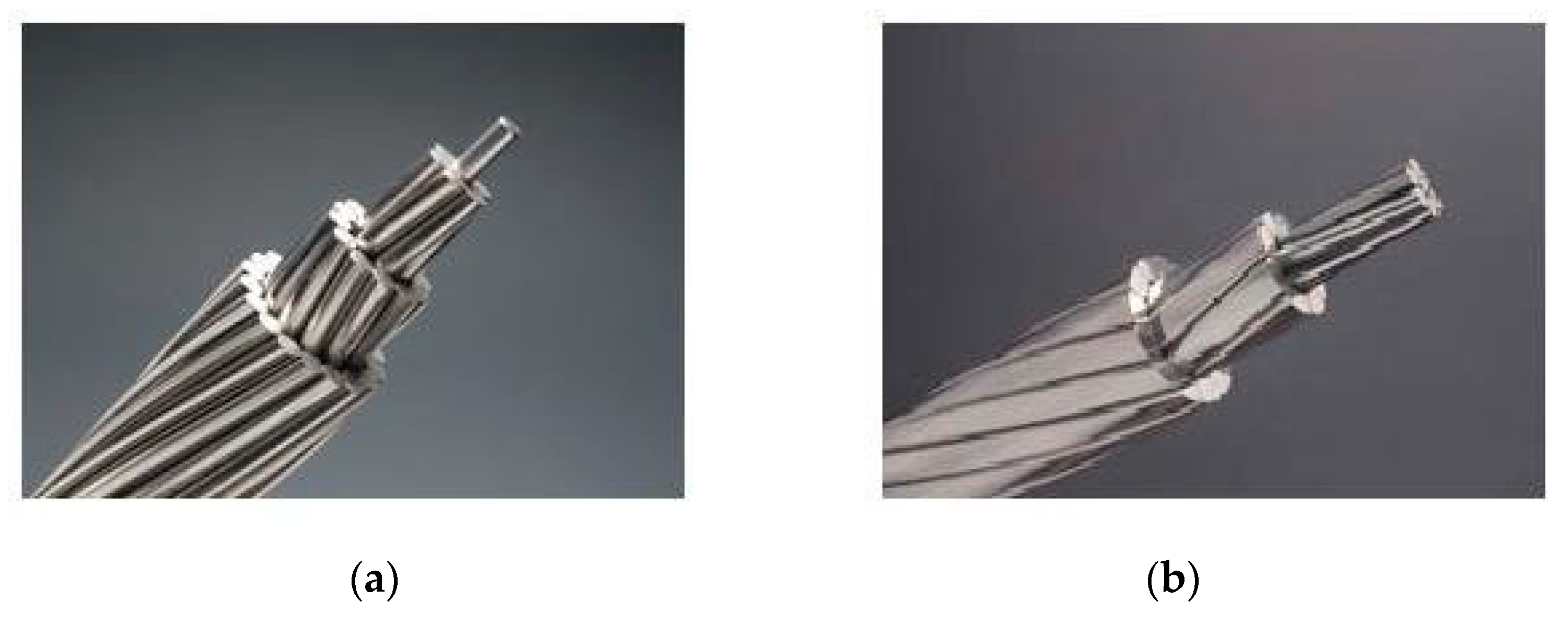
2. Stranded Conductor Geometric Variants

Stranded conductors are normally discriminated on the basis of strand geometry as well as the compactness technique used in the conductor development [57]. The geometric configuration of stranded conductors used in UGCs and OHLs are specified in Table 1, and Figure 1 represents circular and trapezoidal strand conductors [57].

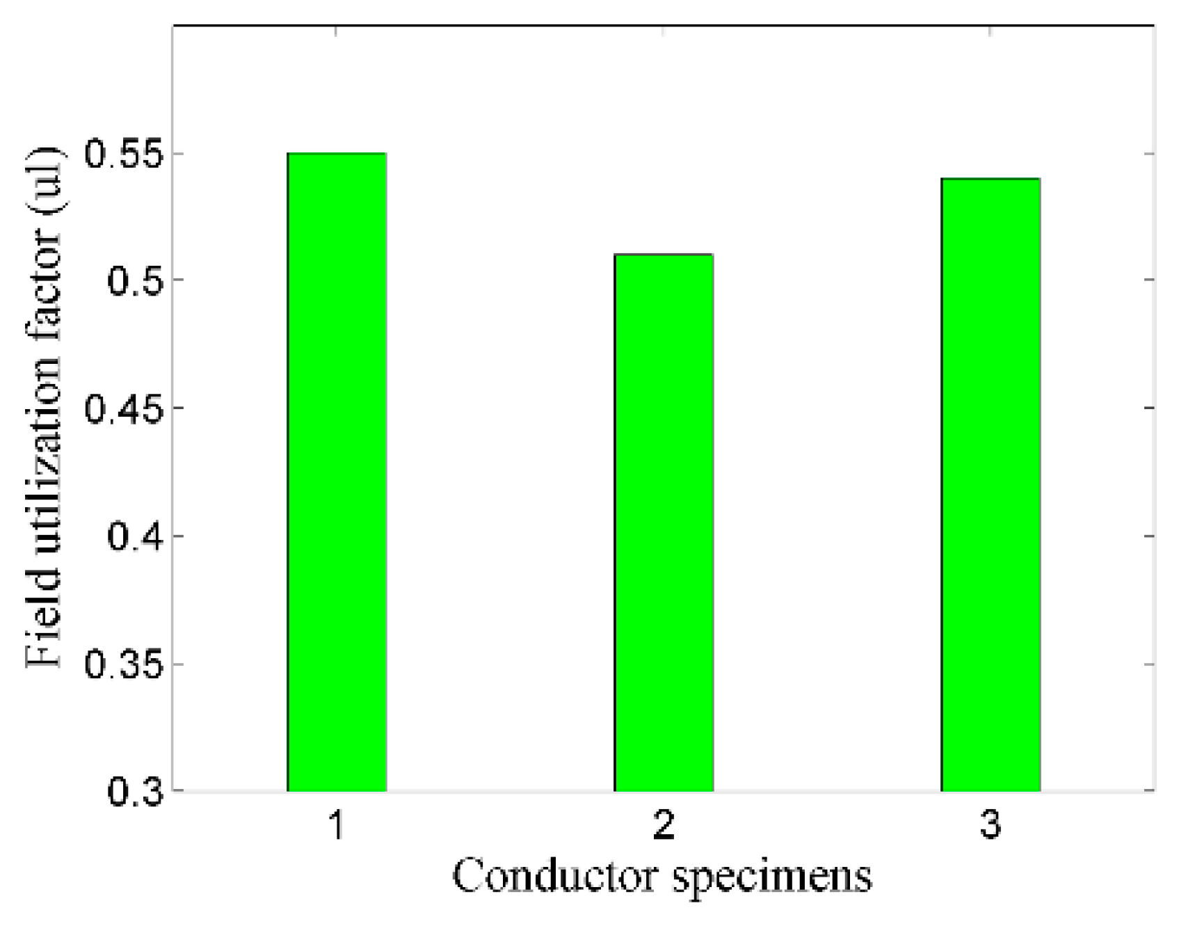
Electric Field Dispersal Regarding Strand Geometry

The electric field dispersion in a region normally depends upon electrode geometry, surface irregularity, and gap distribution [58]. The field utilization factor (FUF) gives an idea of the effective utilization of field space and facilitates analysis of the electrostatic stresses imposed upon the dielectric material. In general, the FUF can be evaluated through Equation (1), where Eavg denotes the average electric field and Emax denotes the maximum electric field. Further, pertaining to its coaxial configuration, the FUF for an FGIL can be calculated through Equation (2), where R is the enclosure’s radius in millimeters and r is the conductor’s radius in millimeters [41].
η   =   E a v g E m a x
F   =   r · ( ln R r ) R   r

3. Design and Analysis

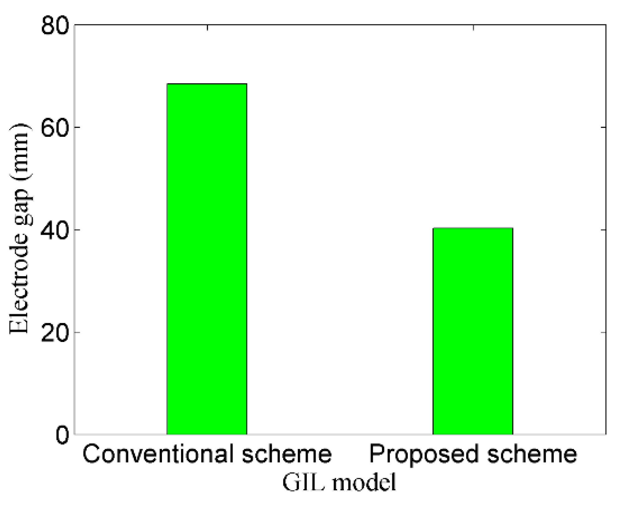
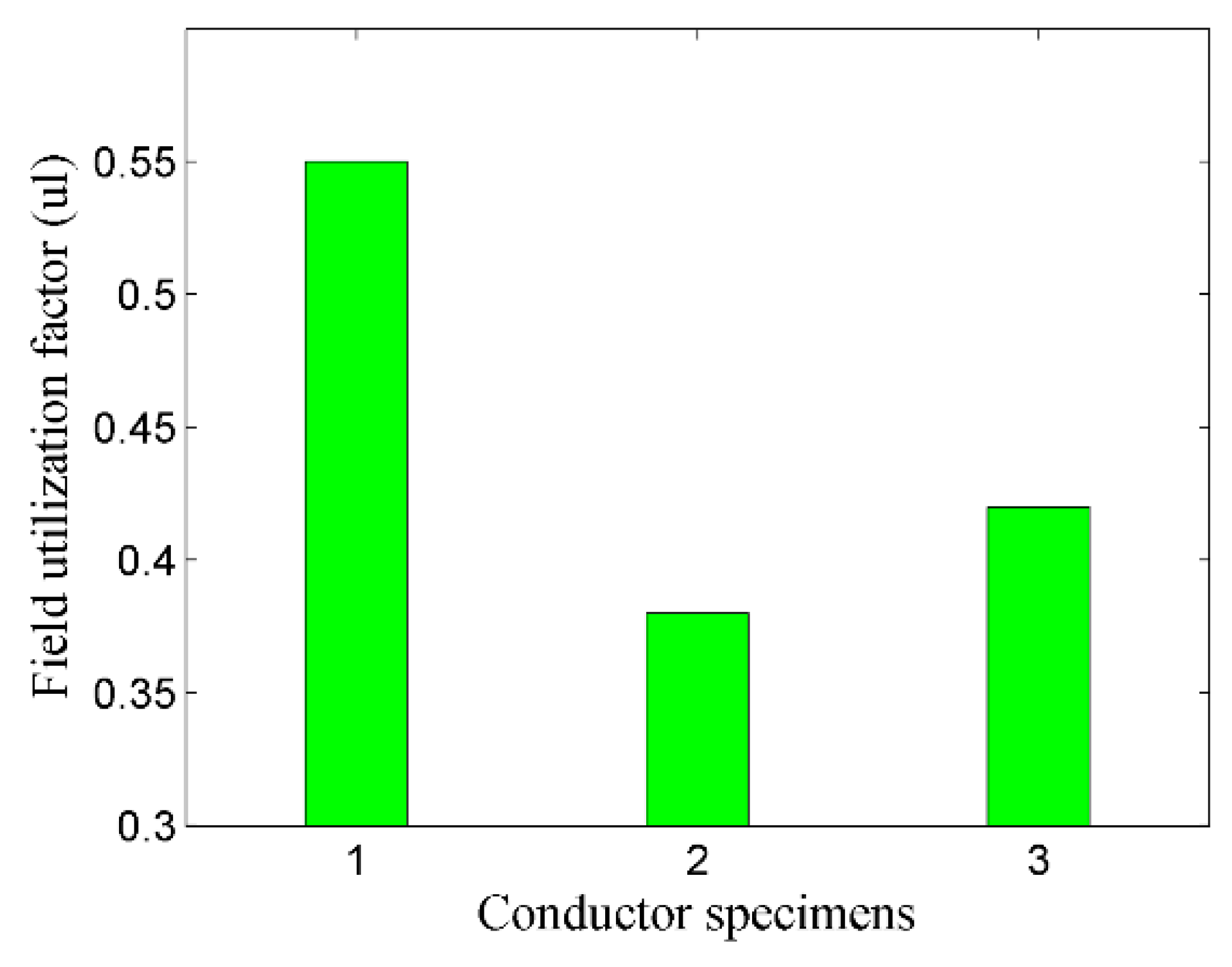
3.1. Dimensional Optimization of FGIL Enclosure Apropos of Stranded Conductor

The selection of a stranded conductor for an FGIL requires reconsideration regarding enclosure diameter because the FUF for GILs is normally kept in the range of 0.5 to 0.6 and is directly related with their dimensional specifications [24,41,42]. In a standard GIL, enclosure and conductor dimensions are normally selected to have approximately 1 as the solution of the logarithmic expression in Equation (2). That is, the enclosure diameter is approximately three times the conductor diameter [24,41,42]. However, in order to have an optimized enclosure size regarding the required FUF, Equation (2) was rearranged for enclosure dimension and expressed as Equation (3). Considering that Equation (3) appears as an implicit equation, its solution was performed through the Newton–Raphson iterative (NR) method in MATLAB® with the required accuracy up to four decimals and an initial estimate of 50 for the unknown parameter (i.e., enclosure radius). The estimated values and their errors showed a converging trend, and the enclosure radius finally converged in eleven iterations up to the required accuracy. Dimensional appraisal of conductor and enclosure revealed that the enclosure was approximately three times the conductor size and resulted in the achievement of the desired FUF.
R   =   r e x p ( F · ( ( R r ) 1 ) )

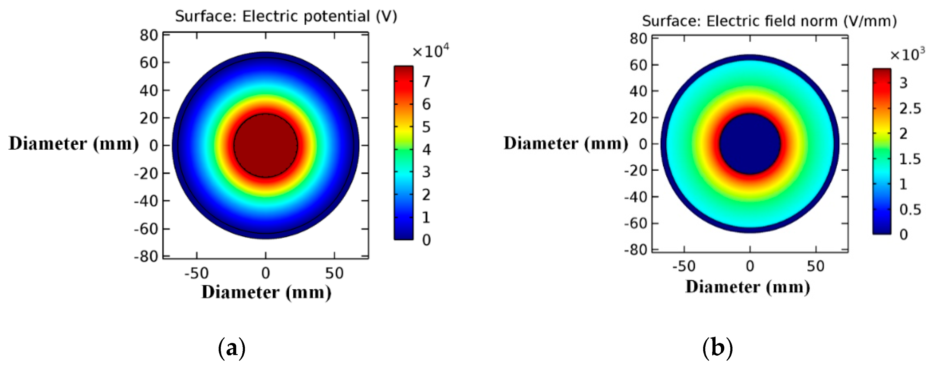
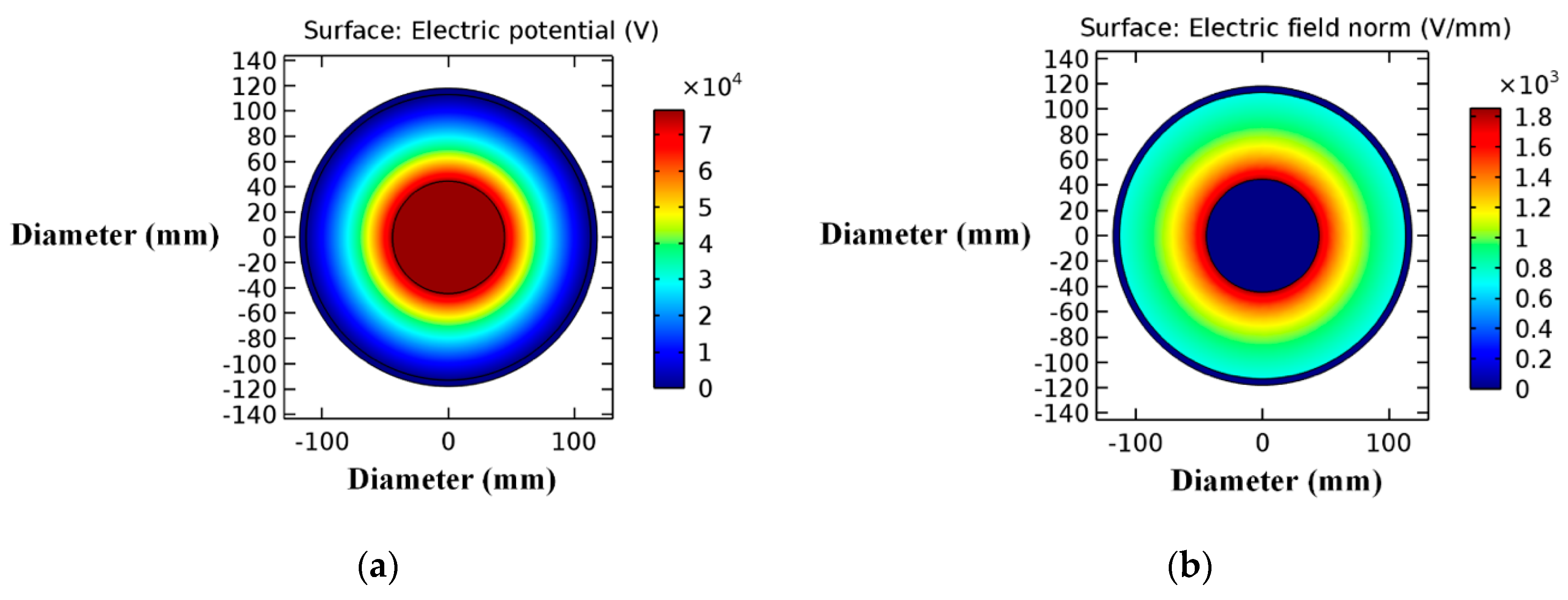
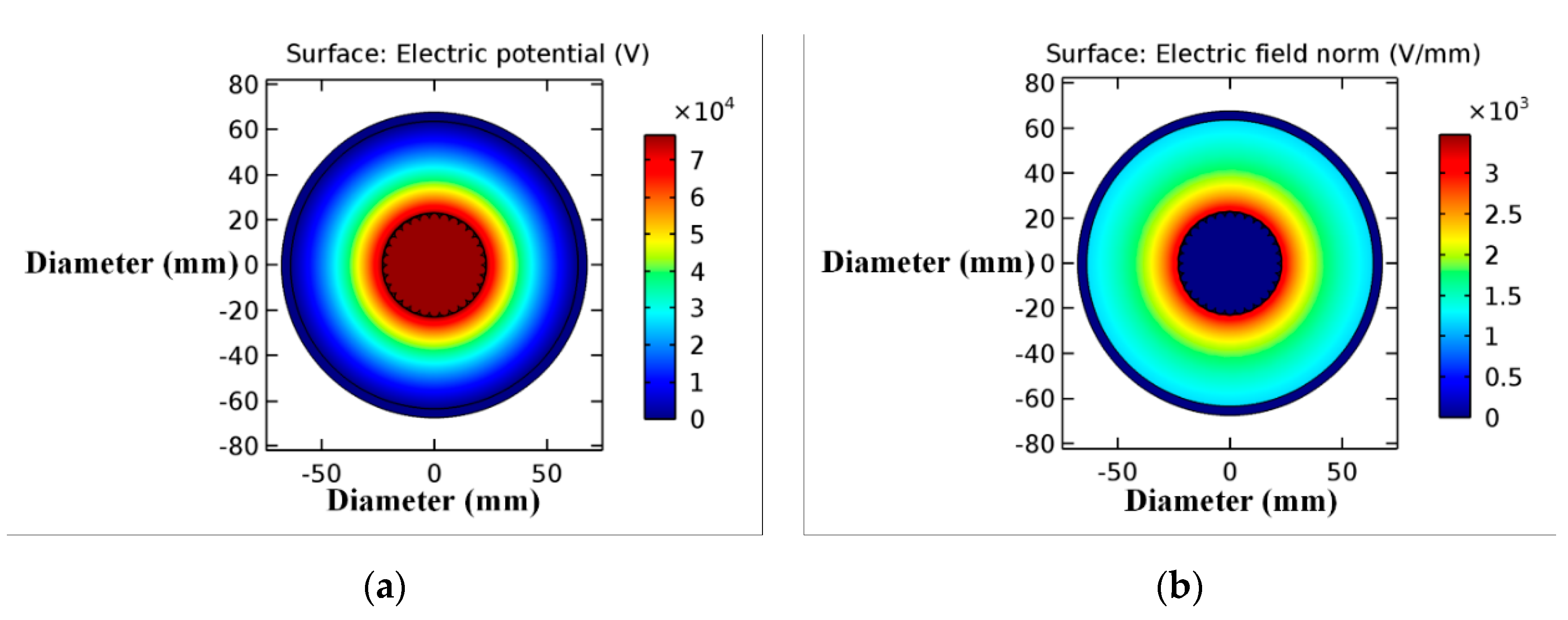
3.2. Electrostatic Field Optimization of the FGIL

Electric field optimization is obligatory in electrical systems in order to eradicate the prospect of dielectric failure due to partial discharge or gap discharge [58]. Considering the stranded conductor as a potential candidate for pliable GILs and concerning its surface irregularity, detailed electrostatic appraisal is essentially required for the proposed scheme. Protrusions and surface irregularities in stranded conductors may lead to escalated electric fields on the conductor’s surface contour, which may result in detrimental partial discharge activity followed by dielectric strength degradation due to streamers [43,44,45,58]. Thus, considering the importance of field dispersion in pliable GIL, COMSOL Multiphysics®-based electrostatic analysis was performed for the FGIL regarding the stranded conductor specimens given in Table 2 in comparison to existing GILs in order to achieve minimal electrostatic stresses as per the required standards for gas-insulated equipment. The stranded conductors used in the electrostatic examination were developed using Autodesk Inventor®. Dimensional and technical specifications like electrode gap, thickness, and diameter for the conventional and proposed schemes were based upon ASTM B 232, ASTM B 857, and 132 kV GIL standards along with the evaluations of Section 3.1 [59,60]. Table 2 presents the detailed specifications of different conductor specimens used in the electrostatic stress investigation [59,61,62].

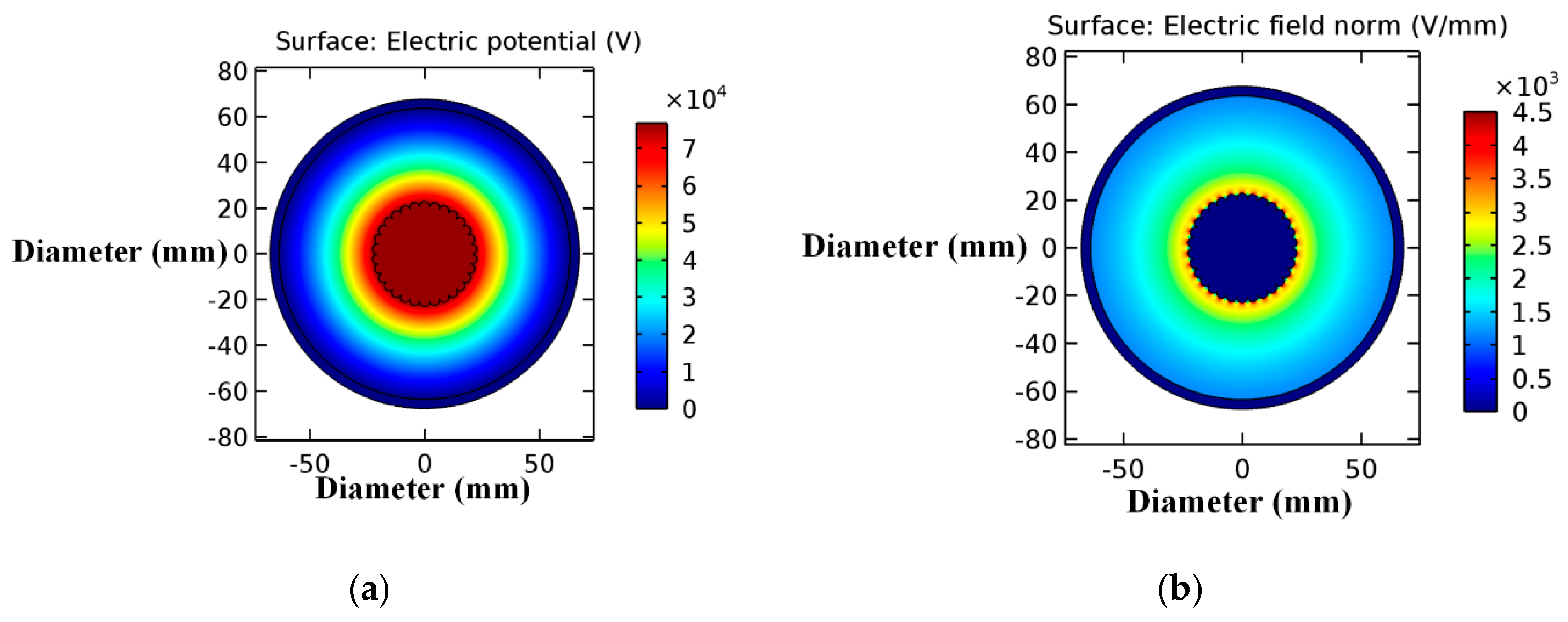
3.2.1. Electrostatic Field Dispersion Apropos of Conventional and Stranded Conductors

Concerning the analysis of the field dispersion along with identification of regions of high electric fields in the proposed GIL scheme, COMSOL Multiphysics®-based models for conventional and pliable GILs were developed and compared regarding the different conductor configurations given in Table 2. Figure 2a,b demonstrates the electric potential and electric field dispersion in a conventional GIL. Figure 3a,b exhibits the electric potential and electrostatic field dispersal in the proposed GIL with a circular strand conductor. Figure 4a,b represents the electric potential and electrostatic field distribution in the proposed GIL with trapezoidal strand conductor. Field dispersion regarding conventional and proposed schemes revealed that stranded conductors resulted in regions of concentrated electric field on the conductor’s surface contour. Figure 5a,b represents the enlarged view of such concentrated electric field regions in the FGIL scheme regarding specimen 2 and specimen 3 of Table 2. Critical perusal of Figure 2, Figure 3, Figure 4 and Figure 5 regarding electric field dispersion reveals that due to protrusions and surface irregularities of the stranded conductors, high electric fields appeared on their surface contour as compared to the conventional scheme with a smooth solid conductor. However, the trapezoidal strand conductor had approximately 10% lower magnitude of maximum electric field stresses due to its relatively smoother profile in comparison to the circular strand conductor. Figure 6 compares the average and maximum electric fields for conventional and proposed GIL schemes regarding the different conductor specimens described in Table 2. Further, Figure 7 compares the FUF for conventional and proposed GIL schemes regarding the different conductor specimens described in Table 2. Detailed analysis of Figure 6 and Figure 7 revealed that the surface irregularity of stranded conductors in the proposed pliable GIL resulted in objectionably high electric fields regarding specimen 2 and specimen 3 in comparison to the conventional scheme regarding specimen 1. Further, the field utilization factor was also reduced by 31% and 23% respectively for specimens 2 and 3 regarding proposed pliable GIL in comparison to specimen 1 regarding the conventional scheme. A probable solution to the above stated problem could be to enlarge the enclosure‘s diameter or to suppress the conductor’s irregularity [63,64,65]. COMSOL Multiphysics®-based simulations were performed for this purpose, which revealed that enclosure enlargement resulted in the minimization of the irregular field distribution and reduced the electrostatic stresses on the conductor’s surface. However, the FUF was reduced in comparison to the standard allowable limit for GILs because as per GIL standards, the enclosure’s diameter should be approximately three times the conductor’s diameter in order to acquire an FUF in the permissible range of 0.5 to 0.6 [17,24,41,42]. The violation of the aforementioned constraint regarding enclosure diameter resulted in a poor field utilization factor for the proposed scheme, which is objectionable as per GIL standards. Thus, remedial measures regarding suppression of irregularities in the stranded conductor must be taken in order to achieve the required FUF and eradicate concentrated electric field regions.

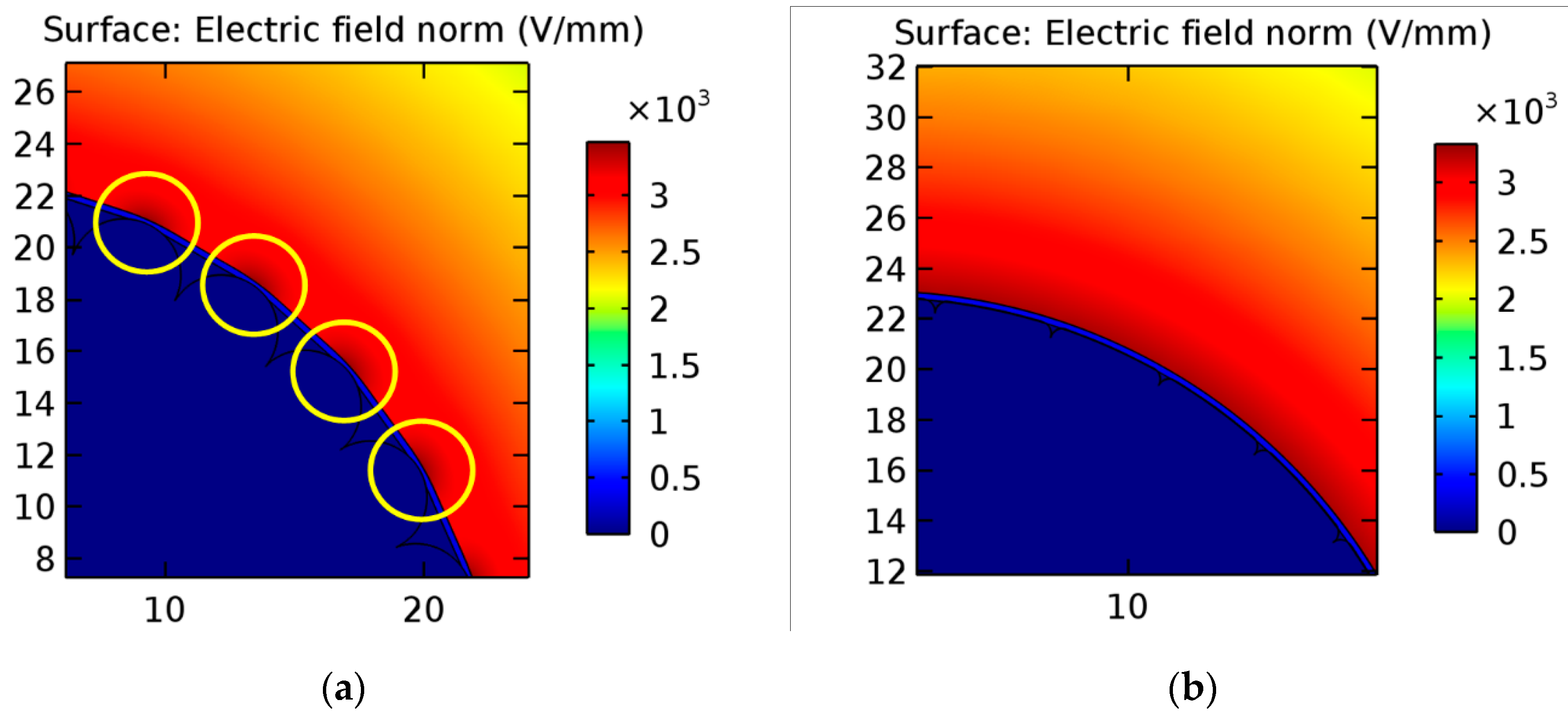
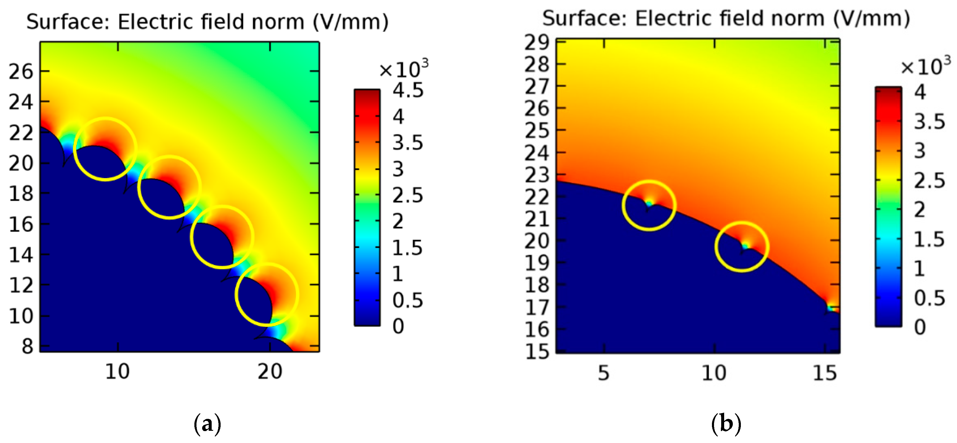
3.2.2. Contour Irregularity Suppression of Stranded Conductor

Considering the objectionable deviations in the field utilization of the proposed FGIL due to stranded conductors, irregularity suppression essentially needs to be done in order to acquire the required FUF. A probable solution could be the implementation of a silicon carbide (SiC)-impregnated polyester-based SCF of 0.1–0.4 mm thickness on the stranded conductor in order to acquire a relatively smoother conductor profile [39,66,67]. The implementation of such film-coated stranded conductors in gas-insulated equipment necessitates detailed electrostatic and dielectric appraisal, as no published research regarding the implementation of field-graded stranded conductors in gas-insulated equipment exists to date.

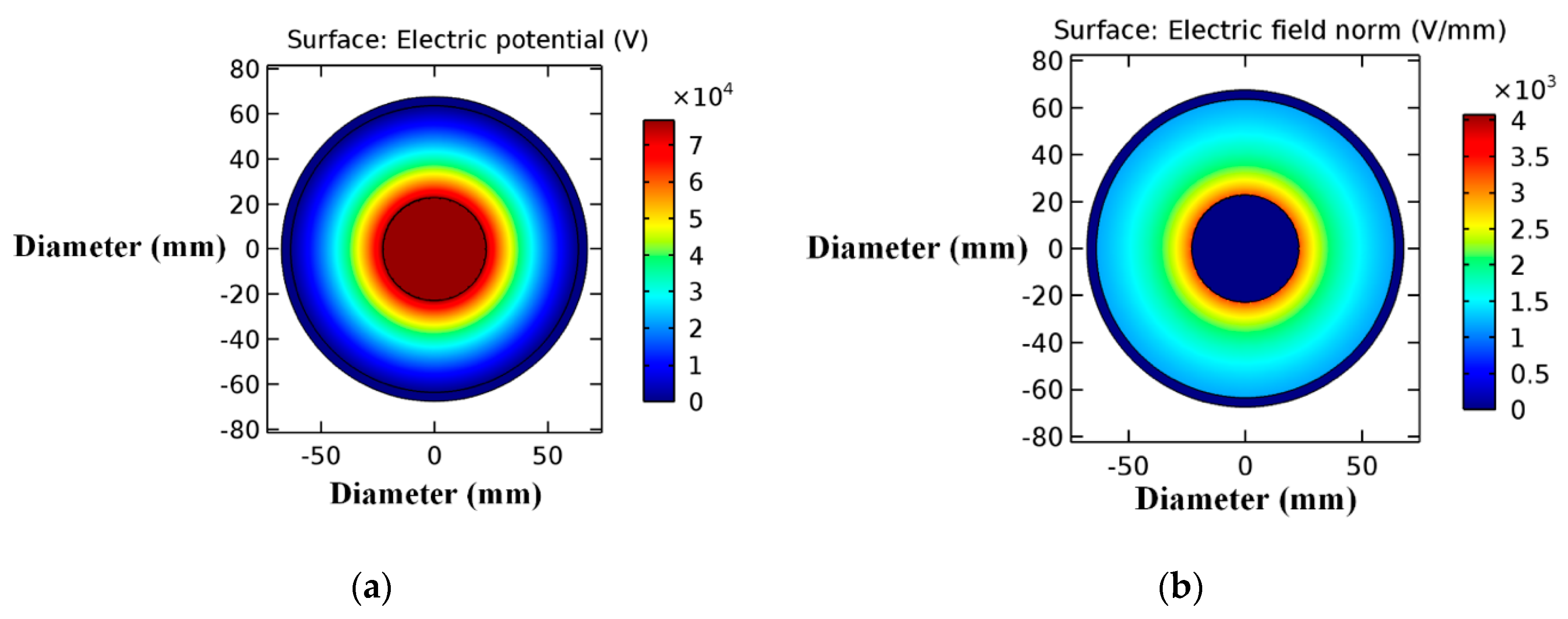
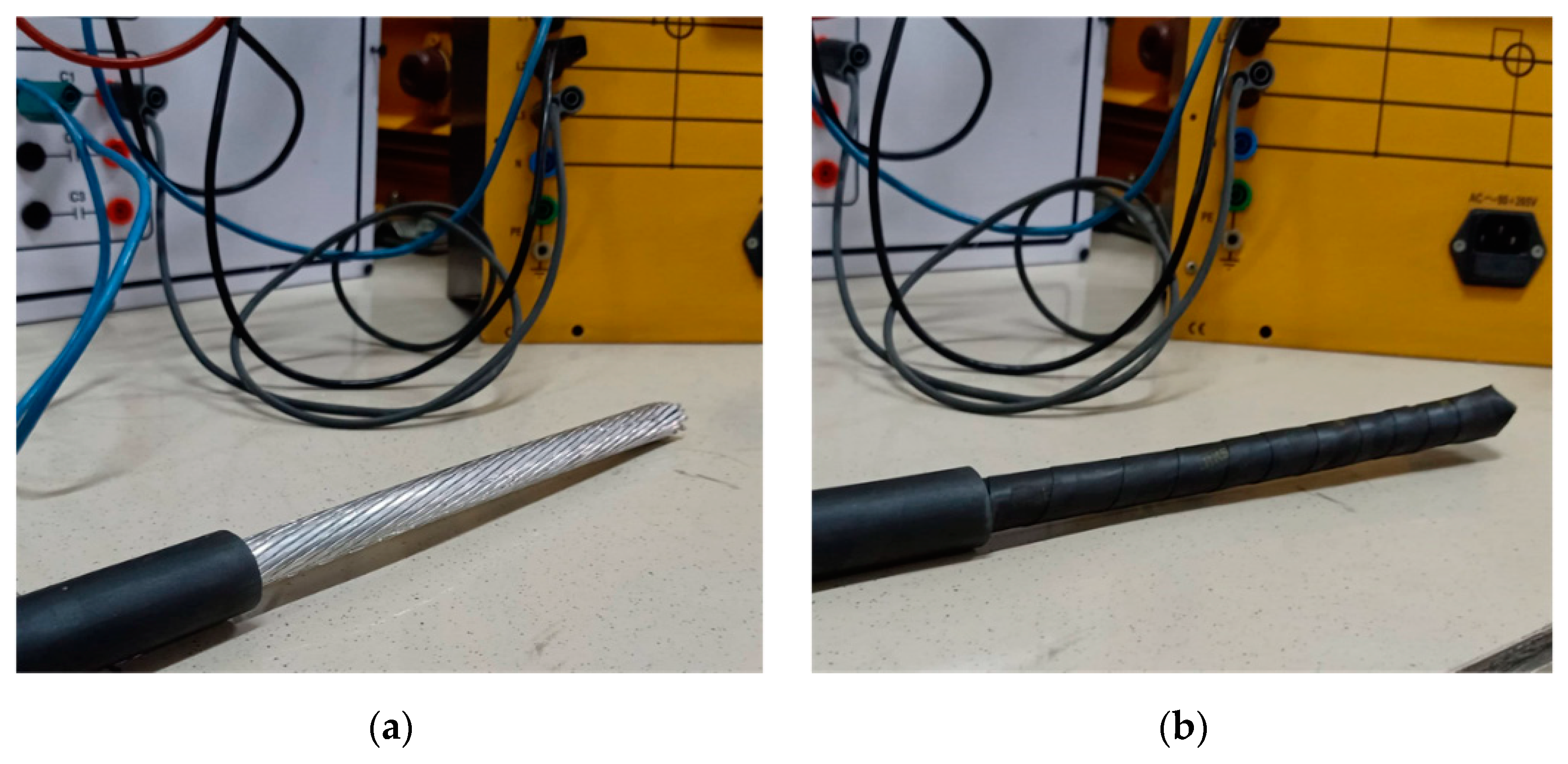
3.2.3. Electrostatic Field Dispersion Apropos of Film-Coated Stranded Conductors

Concerning the effectivity of irregularity suppression for stranded conductors in terms of field utilization factor and electric field dispersion, SCF-coated stranded conductors were developed using Autodesk Inventor®. Dimensional specifications for the SCF-coated stranded conductors were based upon the ASTM B 232 and ASTM B 857 standards for stranded conductors, and the film thickness was based upon the standard film thickness for power cables [57,61,68]. Detailed specifications of the developed film-coated stranded conductors along with conventional GIL conductor are given in Table 3. Considering the conductor specimens given in Table 3, COMSOL Multiphysics®-based pliable GIL models were developed and analyzed in comparison to existing GIL schemes so as to achieve the desired electrostatic performance per the standards for GILs. Figure 8a,b demonstrates the electric potential and electrostatic field dispersion in the proposed pliable GIL scheme regarding specimen 2 of Table 3 respectively. Figure 9a,b exhibits the electric potential and electrostatic field distribution in the proposed pliable GIL scheme regarding specimen 3 of Table 3 respectively. Figure 10a,b shows the enlarged view of high electric field regions in the proposed FGIL scheme regarding specimens 2 and 3 of Table 3 respectively. Critical perusal of Figure 5 and Figure 10 reveals that surface irregularity suppression resulted in substantial reduction in electrostatic stresses on the surface contour of the stranded conductor, and improved the field distribution for both stranded specimens of Table 3. However, specimen 3 had approximately 6% lower magnitude of maximum electrostatic stresses due to its nearly circular profile in comparison to specimen 2. Figure 11 compares the average and maximum electric fields for the conventional and proposed pliable GIL schemes regarding the respective conductor specimens of Table 3. Further, Figure 12 compares the field utilization factor of conventional and proposed GIL schemes regarding the respective conductor specimens of Table 3. Detailed analysis of Figure 12 reveals that surface irregularity suppression resulted in achieving a relatively better FUF, with a trivial deviation of 7.5% and 1.8% regarding specimens 2 and 3 of Table 3 as compared to specimen 1 of the respective Table. In addition, a smoother conductor profile due to the SCF coating also resulted in substantial electrostatic stress reductions in the conductor contour up to 23% and 21% regarding specimens 2 and 3 of Table 3 in comparison to respective simple stranded conductors of Table 2. Further, in comparison to aluminum conductor steel reinforced (ACSR) and all aluminum alloy conductor (AAAC), due to their compact design, trapezoidal stranded conductors of the aluminum conductor steel supported (ACSS) category exhibit higher ampacity and thermal ratings within the same dimensional specifications [62]. Thus specimen 3 of Table 3 could serve as the optimal candidate regarding thermal, ampacity, and electrostatic requirements along with the desired flexibility for the proposed pliable GIL.

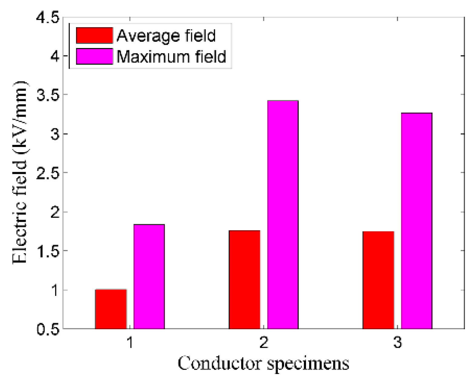
3.3. Dielectric Appraisal of FGIL Apropos of the Stranded Conductor

In order to analyze the breakdown characteristics of the dielectric medium in the stranded-conductor-based FGIL model developed above, an analysis was performed regarding its minimum discharge voltage (i.e., breakdown voltage, BV). Existing methodologies for discharge voltage calculation can be categorized on the basis of the streamer breakdown theory as well as the critical field strength evaluations [58,69]. Both methodologies were incorporated in this research in order to ascertain the practicability of the suggested conductor scheme for a pliable GIL.

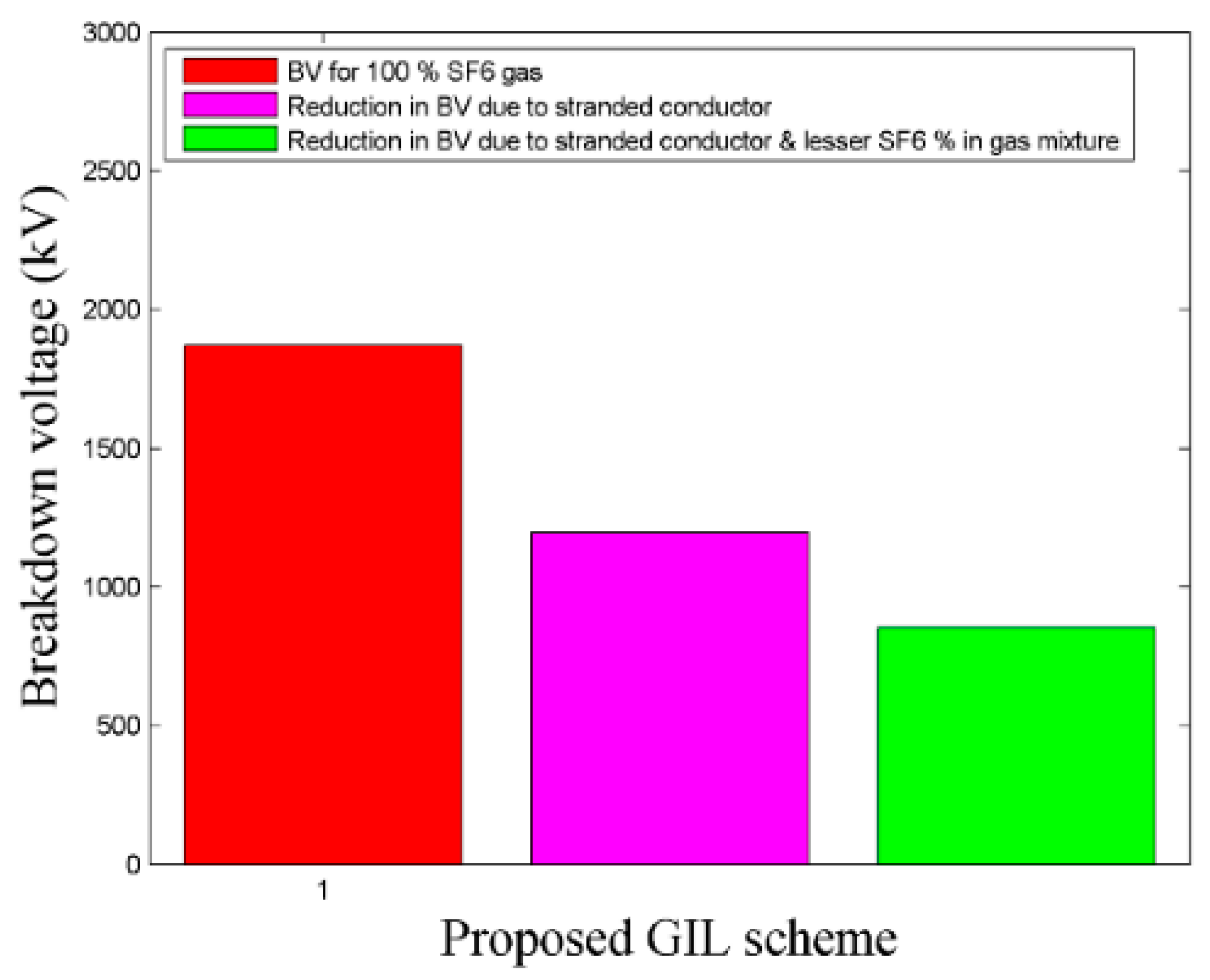
3.3.1. Breakdown Voltage of the Proposed Configuration Regarding Streamer Breakdown Theory

Per the streamer breakdown theory, a streamer may result in a partial discharge such as a corona or a complete gap discharge, and the associated potential level is considered as the breakdown voltage [58,69]. The minimum breakdown voltage in SF6 insulated equipment can be evaluated by using Equation (4), where BV is the breakdown voltage in kV, P is the gas pressure in kPa, and d is the electrode gap in centimeters [58,69]. However, the effect of electrode surface irregularity should also be considered, as it significantly degrades the minimum breakdown voltage. Considering the conductor’s surface irregularity in the model developed above, Equation (5) can be used for the evaluation of the minimum breakdown voltage, where BV is the breakdown voltage in kV, C is the curvature factor, d is the electrode gap in centimeters, F is the field utilization factor, P is the gas pressure in kPa, and S is the electrode roughness factor [58]. Further, considering the case when the dielectric medium comprises sulfur hexafluoride and nitrogen gases at a ratio of 20:80, its breakdown strength will be lesser in comparison to pure SF6 gas, and will depend upon the percentage of SF6 in the mixture. Thus, Equation (6) can be used for the evaluation of possible degradation in the minimum breakdown voltage of the gas mixture [69]. Figure 13 shows the electrode gap comparison between the 132-kV conventional and proposed GIL scheme which is further used in the evaluation of the minimum breakdown voltage for the proposed scheme. Reduction in electrode gap resulted due to the reduction of conductor diameter from 89 mm to 44.5 mm, as the proposed scheme comprises a stranded aluminum conductor whereas the conventional scheme comprises a hollow aluminum conductor. However, the ampacity of both conductors was kept approximately the same. Further, the diameter of the ground electrode was also reduced from 226 to 127.2 mm, as it is based on the dimensional evaluations performed in Section 3.1 regarding the standard field utilization factor as well as the standard dimensional specifications for GILs. Figure 14 represents the breakdown voltage for 100% SF6 content and the respective reduction in this breakdown voltage due to surface irregularity of the stranded conductor using Equations (4) and (5). Moreover, it also highlights the reduction in breakdown voltage due to the reduced SF6 content in the SF6 and N2 gas mixture through Equation (6). Critical analysis of Figure 13 and Figure 14 shows that the BV for the given dimensional and operational specifications of the proposed 132 kV pliable GIL was well above the normal operating voltage and the standard basis insulation level (BIL) value of 132 kV. Thus, per the evaluated dimensional specifications, the proposed FGIL scheme exhibits good dielectric withstand capability.
B V   =   1.321 · ( P d ) 0.915
B V   =   0.8775 · F · S · C · P · d
m   =   38.03 · n 0.21

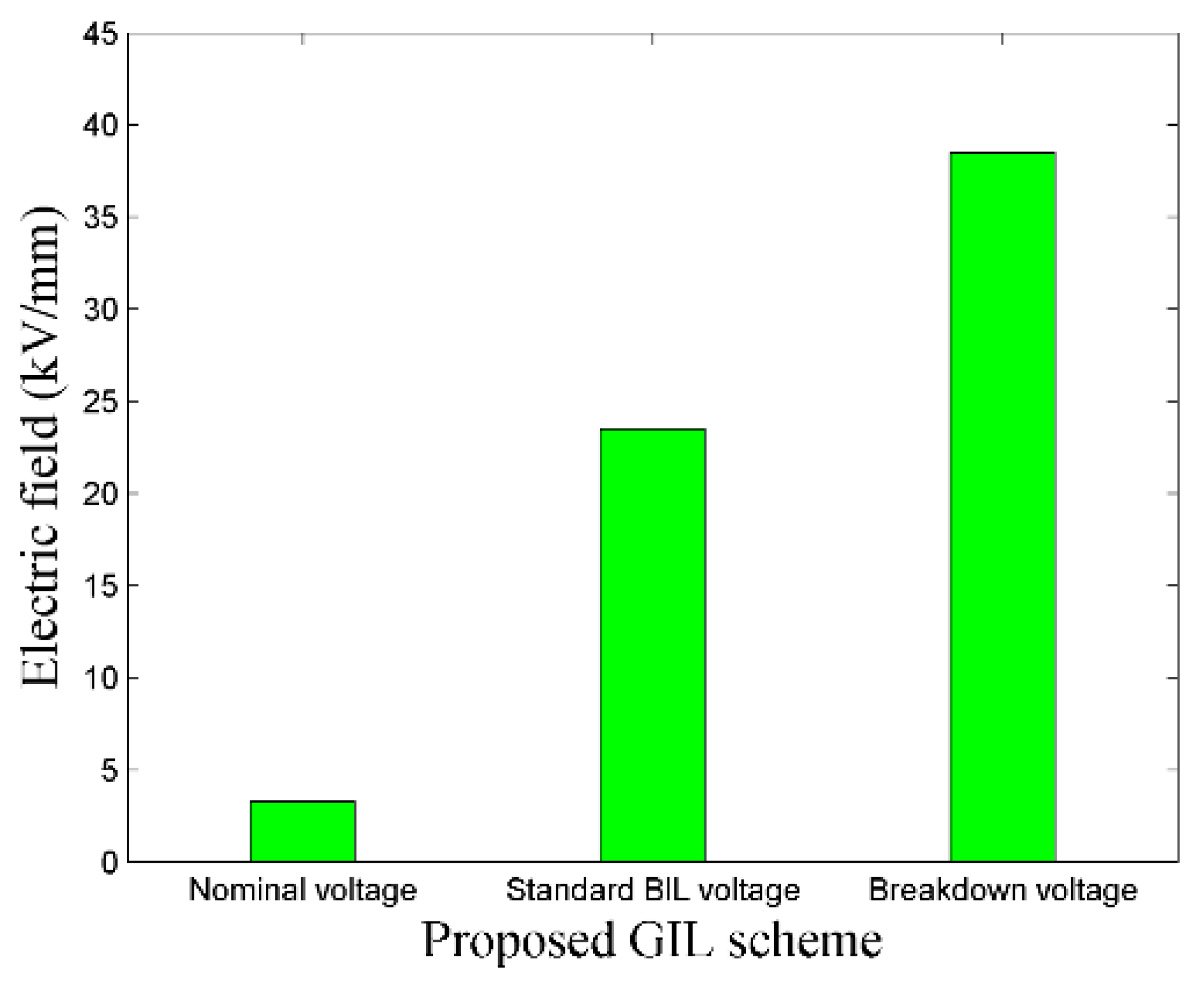
3.3.2. Breakdown Field Strength of the Proposed Configuration Regarding Critical Field Intensity Theory

In the critical field intensity method, the breakdown voltage of a dielectric gas is associated with critical field, electrode gap, FUF, electrode surface irregularity, and gas pressure [69]. According to this theory, the operational and design magnitudes of the electric field should be well below its critical value in order to avoid dielectric breakdown through avalanche [58]. Further, in accordance with GIL standards, the typical allowable design criterion regarding electric field strength is approximately 20 kV/mm, and might be higher such that the influenced region is not substantially enormous [24]. Thus, concerning the practical viability of the proposed 132-kV FGIL scheme, its electrostatic field appraisal regarding operational, design, and critical field values is essentially required. The operational and design values of the electric field in the proposed pliable GIL could be evaluated through Equation (7) by considering the normal operating voltage and standard BIL voltages, respectively [41]. Further, Equation (7) can be rearranged by considering Equations (1), (5), and (6) for the evaluation of the critical electric field as shown in Equation (8) [41,58]. In Equation (8), BV is the breakdown voltage and EC is the critical electric field as evaluated on the basis of Equations (5) and (6). Figure 15 shows the comparison regarding the operational, design, and critical electric fields for the proposed scheme. Critical perusal of Figure 15 shows that the operational and design values for the electric field were well within limits as specified by the standards for gas-insulated equipment, and both field magnitudes were much less than the critical field value. Thus, per the appraised dimensional specifications, the proposed 132-kV FGIL scheme exhibits good electrostatic stress withstand capability.
E m a x   =   U 0 r · ln ( R r )
E c   =   B V f · ( R r )

3.4. Field Stress Distribution in Bended Segment of FGIL

In order to analyze the practicability of the proposed scheme for bent segments, simulation regarding electrostatic stress distribution for FGIL in case of bend was performed in comparison to its equivalent straight model. For the said purpose, 20-m-long straight and bent FGIL models were developed using Autodesk Inventor®, and further field distribution and FUF for the two models were analyzed using COMSOL Multiphysics®. Line bending was performed as per the permissible longitudinal minimum bending radius (LMBR) of reinforced polyvinyl chloride (RPVC), and field distribution as well as FUF analysis for the respective FGIL models was performed regarding axial and radial cross sections. Critical appraisal of bent and straight FGIL models regrading axial cross section revealed a trivial deviation of 0.7% and 0.8% in electric field intensity and FUF, respectively. Moreover, detailed comparison of two FGIL models regrading radial cross section showed a slight deviation of 0.4% and 0.5% in electric field intensity and FUF, respectively. Minimal deviation in the compared models was observed because longitudinal bending as per LMBR limits resulted in negligible circumferential deformation as well as gradual bending. Thus, field magnitude and stress distribution for the bent line segment were nearly the same as those for the straight line segment.

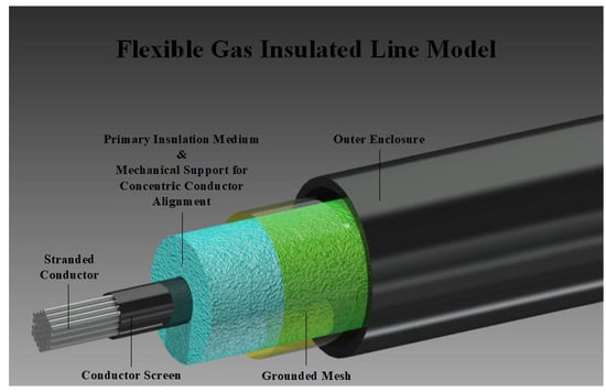
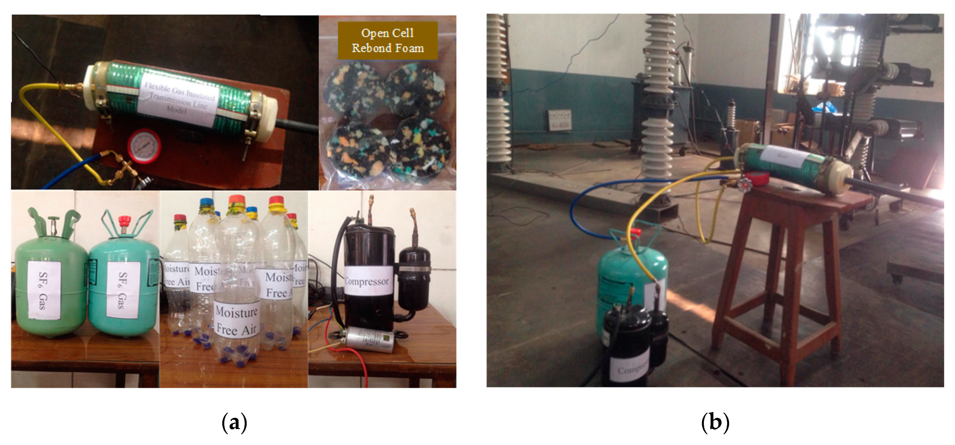
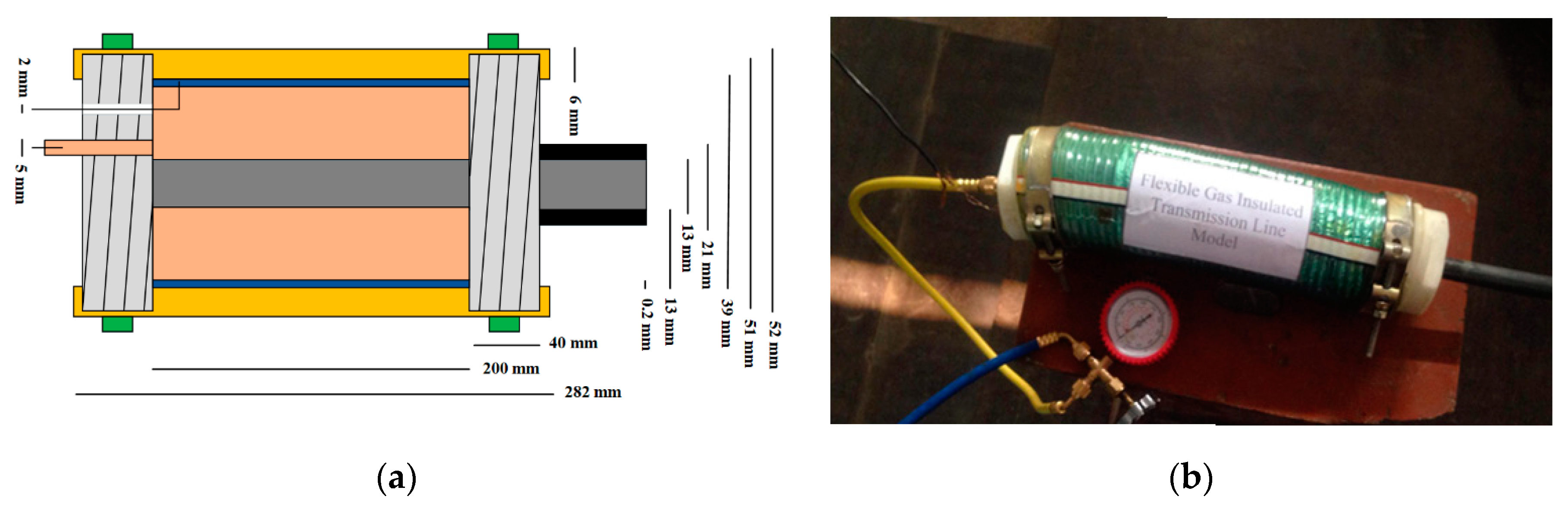
4. Fabrication of the Scaled FGIL Model

Regarding the practical viability of the proposed scheme, an 11-kV scaled-down model of the 132-kV FGIL was fabricated on the basis of electrostatic modeling by replicating the field distribution of a high-voltage GIL for a scaled down model [17,24,41,42]. Considering the standard FUF and allowable maximum electric field for the 132 kV GIL, dimensional specifications regarding enclosure and conductor of the 11 kV scaled down model were evaluated per the technique described in Section 3.1. After finalizing the dimensional specifications, the scaled down model was first analyzed and compared with the actual 132 kV GIL model by using the technique described in Section 3.2 and Section 3.3 regarding field distribution, field magnitude, FUF, and breakdown characteristics using COMSOL Multiphysics®. Then, a practical model was developed in order to conduct experimental investigations. RPVC was used as the enclosure material, and braided metallic mesh covered with aluminum foil was placed inside the enclosure as the ground terminal. A stranded aluminum conductor was placed inside the RPVC pipe, and threaded Teflon corks were used to prevent any gas leakage from pipe ends. Further, metallic clamps were placed on Teflon corks in order to avoid cork slippage and gas leakage at high gas pressures. Electrically pretested open cell rebond foam of 105 kg/m3 density was used to achieve concentric conductor alignment inside the enclosure [34]. A gas charging and discharging system was implemented to pressurize the flexible GIL model at different gas pressures, and to create vacuum. The material and thickness of SCF were selected per the scheme described in Section 3.2.2 and Section 3.2.3. The specified FGIL model for high-voltage experimentation was developed for simple as well as SCF-wrapped stranded conductors. Figure 16a,b shows the simple and SCF-coated stranded conductors used in the development of the FGIL models respectively. Figure 17a shows the dimensional specifications of the designed flexible GIL model, and Figure 17b shows the fully developed model.

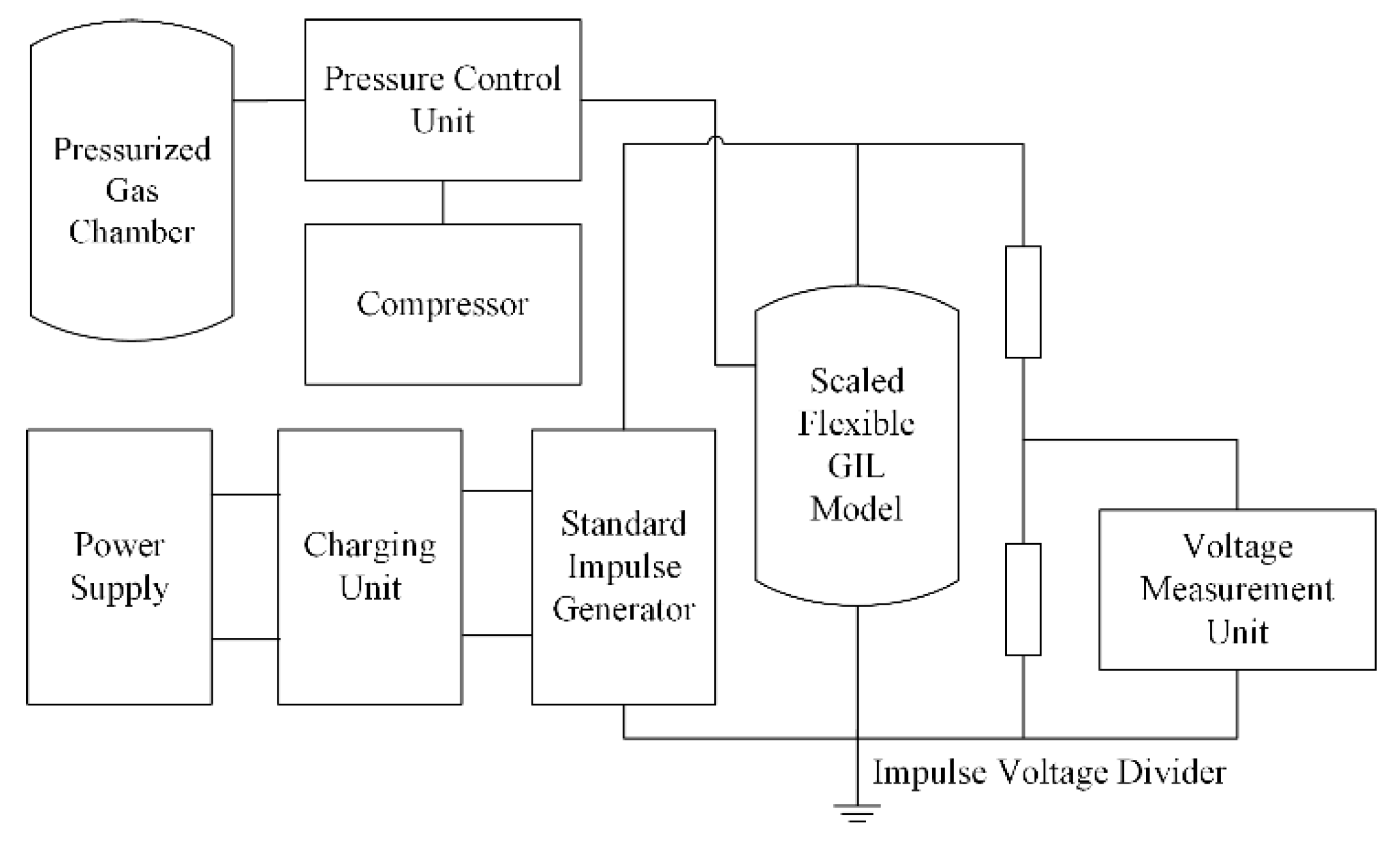
5. Experimental Setup Development

Pertaining to the practicability of the proposed scheme, an experimental setup was developed regarding lightning impulse and power frequency disruptive discharge tests for the proposed scheme, as per the IEC 60060-1:2010 standard [70]. FGIL models, fabricated respectively with simple and SCF-coated stranded conductors, were used in this experimental investigation. Concerning the lightning impulse discharge tests, U50 for different GIL specimens was determined by Up–Down method, where for power frequency discharge an average of ten disruptive discharges was considered. A compressor and a pressure control unit were incorporated in order to create a vacuum in the developed GIL model along with the injection of dielectric gas at the desired pressure. Gas-insulated equipment normally utilizes pure SF6 or a mixture of SF6 and N2 at a ratio of 20:80, but the required gas pressure in the latter case was almost doubled as compared to the prior case. Considering the security concerns associated with the high-pressure containment of SF6/N2 mixture at the laboratory level, pure SF6 gas was used, as it would result in a significant reduction of the required gas pressure without compromising the insulation characteristics. A block diagram of the experimental setup is shown in Figure 18. Figure 19a represents the different components used in the high-voltage experimentation, while Figure 19b represents the experimental setup placed in a high-voltage laboratory.

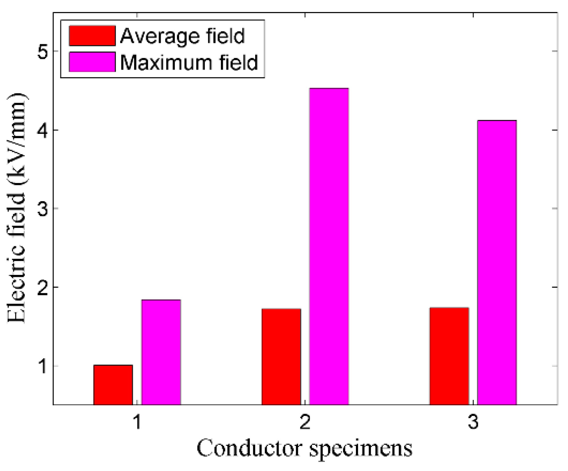
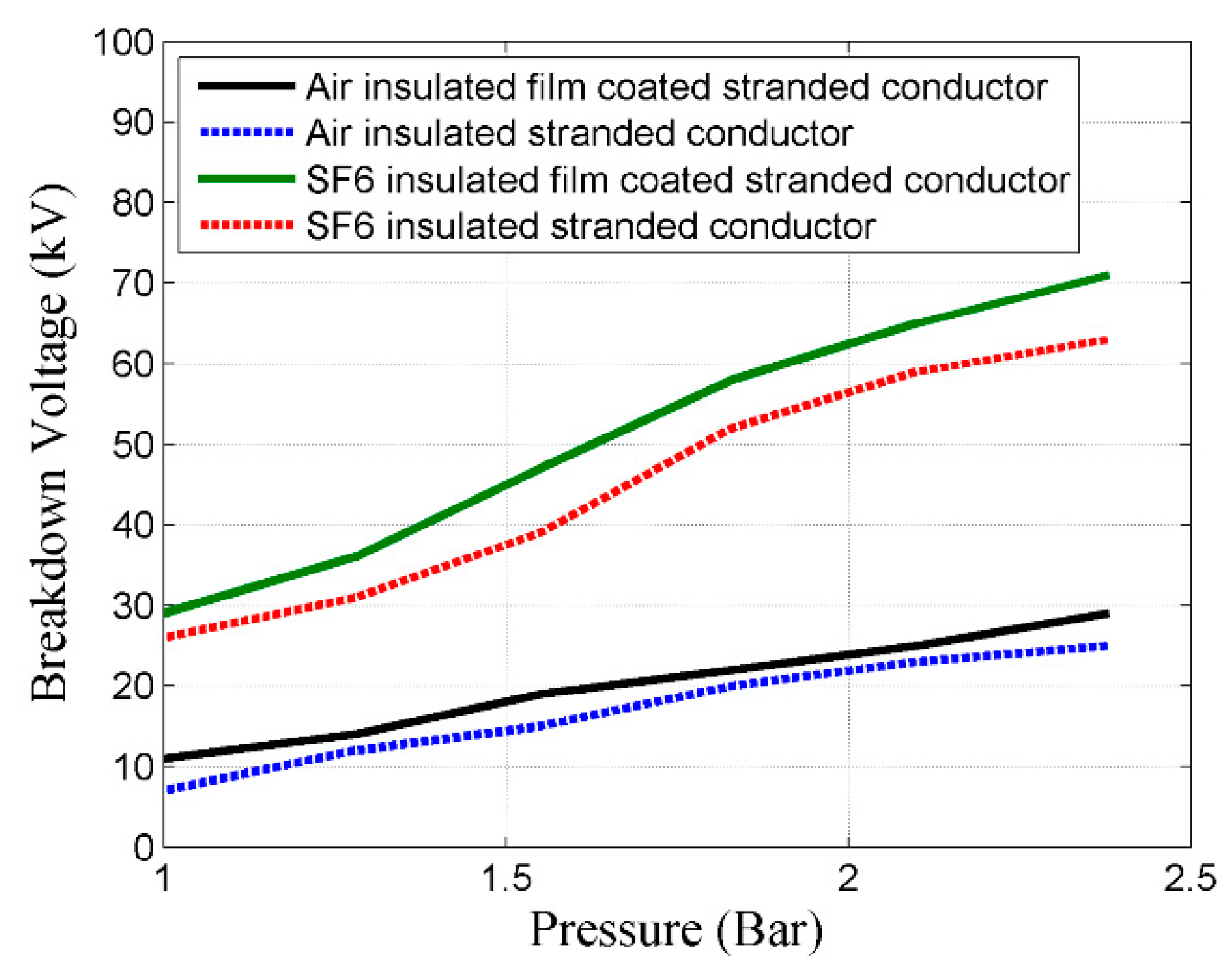
5.1. Dielectric Breakdown Analysis of the Fabricated FGIL Models

Experimental analysis apropos of the dielectric breakdown of the developed FGIL models was performed for SF6 and air gases at different gas pressures in order to investigate the power frequency and impulse discharge characteristics of the FGILs.

5.1.1. Power Frequency Discharge Test

In order to appraise the dielectric characteristics of the FGILs regarding simple and film-coated stranded conductors, power frequency discharge tests using air and SF6 were performed for the fabricated FGIL models. After creating vacuum in the FGIL models, moisture-free air was filled at different gas pressures from 1 to 2.5 bar, and the discharge voltage was noted for both GIL models. Followed by air, similar power frequency discharge tests were performed regarding SF6 gas for both FGIL specimens at different gas pressures from 1 to 2.5 bar. Figure 20 shows the disruptive discharge test results of air- and SF6-filled simple and film-coated stranded-conductor-based FGIL models under different gas pressures. Critical analysis of Figure 20 reveals that the discharge voltage increased with increasing gas pressure in all cases. However, the FGIL model with a film-coated stranded conductor had relatively higher discharge voltages in air as well as sulfur hexafluoride respectively in comparison to the FGIL model with a simple stranded conductor. Further, pertaining to their higher dielectric strength, SF6-filled FGIL models achieved higher breakdown voltages at the respective gas pressures.

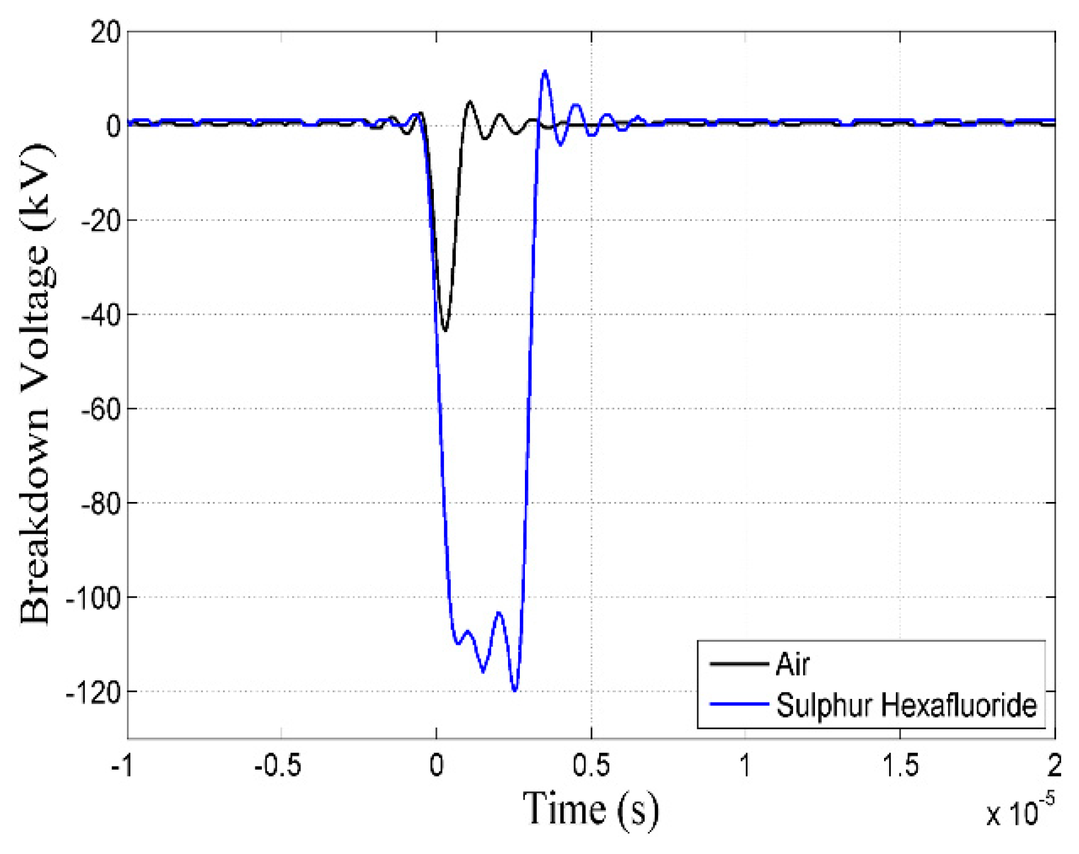
5.1.2. Lightning Impulse Discharge Test

Concerning the impulse withstand characteristics of the developed models, lightning impulse voltage tests were conducted for SF6- and air-filled FGIL models with simple and SCF-coated stranded conductors. After creating vacuum in the FGIL models, moisture-free air was injected at different gas pressures from 1 to 2.5 bar, and lightning impulse discharge voltage was noted for both GIL models. Followed by air, similar lightning impulse discharge tests were performed regarding SF6 gas for both FGIL models at different gas pressures from 1 to 2.5 bar. Figure 21 represents the test results of SF6- and air-filled simple and film-coated stranded-conductor-based GIL models under different gas pressures. Critical analysis of Figure 21 reveals that the impulse discharge voltage increased with increasing gas pressure in all cases. However, the GIL model with a film-coated stranded conductor had relatively higher discharge voltages regarding air as well as sulfur hexafluoride respectively in comparison to the GIL model with a simple stranded conductor. Further, owing to its higher dielectric strength, SF6-filled GIL models achieved the required BIL value for 11 kV beyond 2 bar pressure. Figure 22 shows the recorded waveforms of lightning impulse discharge tests regarding air and SF6 gases at a pressure of 2.38 bar.

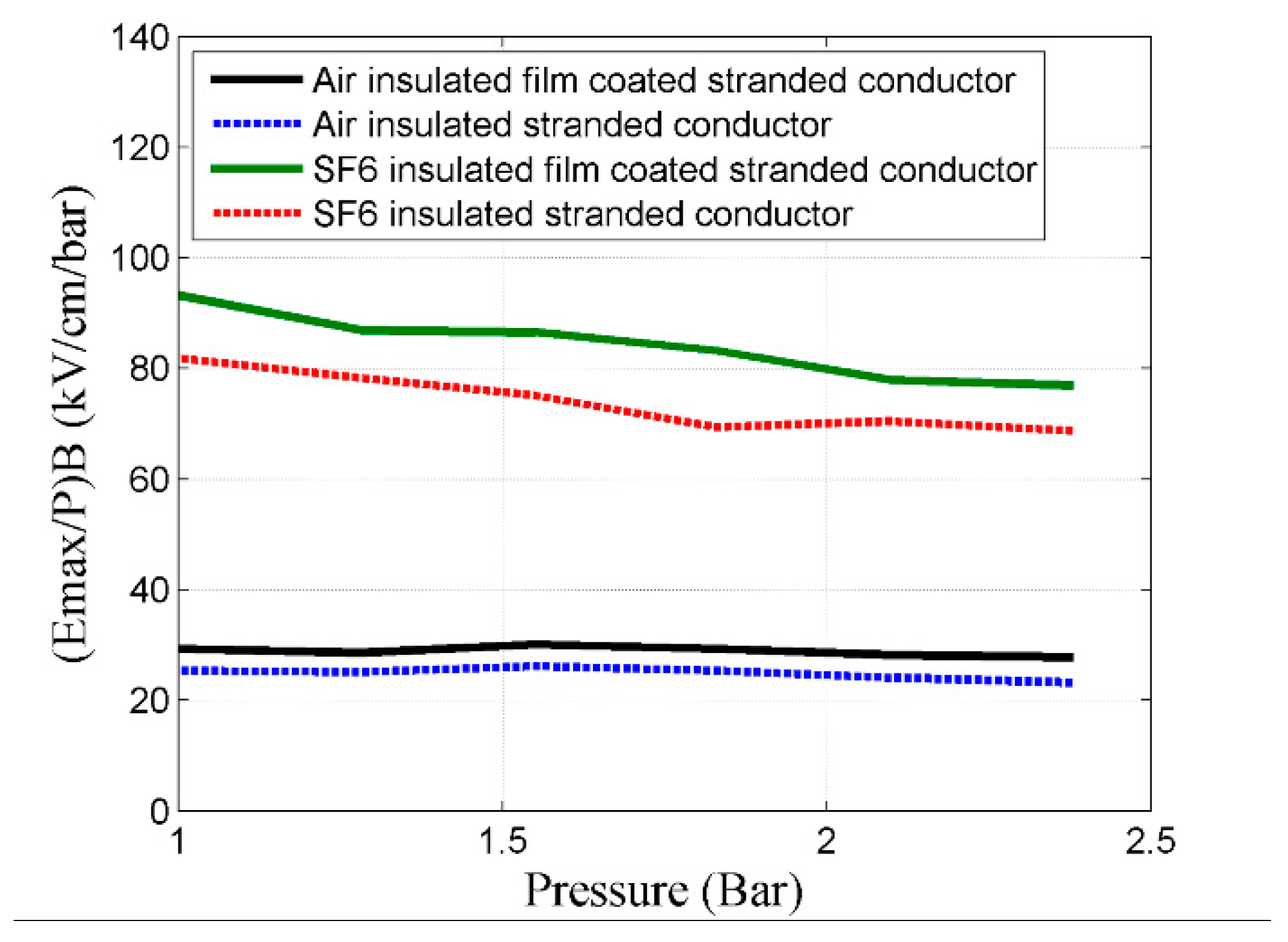
5.2. Critical Field and Breakdown Field Analysis of Fabricated FGIL Models

Concerning the GIL, constraints regarding dielectric design require that the (E/P)Breakdown should be relatively lesser than the (E/P)Critical of the respective dielectric gas. The critical reduced field strength (E/P)Critical at (αη) = 0 regarding air and SF6 per the computations using the BOLSIG+ tool were estimated as 30 kV/cm/bar and 89 kV/cm/bar [41]. Here, η represents the electron attachment rate and α is the coefficient of ionization. Regarding the developed experimental setup, the pressure normalized maximum field strength at U50, (Emax/P)Breakdown, could be evaluated by rewriting Equation (7) as Equation (9), where r represents the conductor’s radius in mm, R represents the enclosure’s radius in mm, and P is the gas pressure in kPa. Figure 23 shows the computations by Equation (9) regarding the experimental findings of lightning impulse discharge characteristics for air- and SF6-insulated FGIL models with simple and SCF-coated stranded conductors. Critical analysis of Figure 23 reveals that the (E/P)Breakdown was lesser than the (E/P)Critical for all scenarios, and furthermore, the SCF coating over the stranded conductor enhanced the breakdown field level for both air- and SF6-insulated FGIL models. Thus, the developed FGIL models fulfill the above-stated dielectric design requirements for GILs.
( E m a x / P ) B r e a k d o w n   =   U 50 r · ln ( R r ) · P

6. Conclusions

Conventional GILs are comprised of a hollow conductor which, owing to its intrinsic rigidity, restricts several application perspectives of conventional GILs specifically in metropolitan areas. Thus, the incorporation of structural flexibility in GILs is essential in order to curtail the operational intricacies of conventional GILs. In this research, FGIL models based on flexible simple stranded and flexible field graded stranded conductors were developed and analyzed regarding electrostatic and dielectric aspects through simulation and experimental assay.
Simulation results revealed that the simple stranded conductors had regions of objectionably high electric fields which ultimately resulted in 31% and 23% degradation of the FUF regarding circular strand and trapezoidal strand conductors respectively in comparison to the conventional GIL. Thus, simple stranded conductors may result in dielectric breakdown due to their surface irregularity, and require contour stress minimization. Possible solutions regarding stress minimization include enclosure enlargement and the suppression of conductors’ irregularity. However, enclosure enlargement significantly deviated the FUF of the FGIL from its allowable range, which is highly objectionable according to GIL standards. Thus, field-graded stranded-conductor-based FGIL models were developed and analyzed through simulation and experimental investigations.
Simulation results revealed that SiC-coated stranded conductors resulted in the achievement of analogous electrostatic characteristics compared to the conventional GIL, with a trivial deviation of 7.2% and 1.8% in the FUF for circular strand and trapezoidal strand conductors, respectively, which are quite acceptable per the allowable FUF range for GILs. Further, critical comparison regarding dielectric aspects revealed that the breakdown voltage for the proposed scheme was approximately 23% above the required standard BIL value for GILs. In addition, electric fields for the proposed scheme regarding standard BIL voltage were approximately 38% below the critical field value and were well within the standard allowable range for electric fields in GILs.
Additionally, experimental investigations of fabricated FGIL models revealed that in comparison to the simple stranded-conductor-based model, the field-graded stranded-conductor-based model exhibited approximately 10–20% and 5–15% higher discharge voltages in power frequency and lightning impulse discharge tests. Moreover, the (E/P)Breakdown for the fabricated pliable models were observed to be relatively lesser than the (E/P)Critical at (αη) = 0 for the respective dielectric gases.
Consequently, simulation and experimental analysis revealed that the proposed conductor scheme could facilitate the achievement of the required dielectric and electrostatic characteristics for FGILs as described by GIL standards. However, the next step of this research is to perform similar high-voltage investigations on a full-scale 132-kV FGIL demonstrator.

Author Contributions

Conceptualization, T.I. and A.A.Q.; Data curation, M.J.A. and H.S.K.; Formal analysis, M.J.A.; Investigation, M.J.A. and A.S.; Methodology, M.J.A.; Project administration, T.I. and A.A.Q.; Software, M.J.A. and H.S.K.; Writing—original draft, M.J.A.; Writing—review and editing, T.I., A.A.Q., and A.S.

Funding

This research received no external funding.

Conflicts of Interest

The authors declare no conflict of interest.

References

  1. Mohammadi, F.; Zheng, C. Stability Analysis of Electric Power System. In Proceedings of the 4th National Conference on Technology in Electrical and Computer Engineering, Tehran, Iran, 19 February 2018. [Google Scholar]
  2. Adedeji, K.; Ponnle, A.; Abe, B.; Jimoh, A. Effect of increasing energy demand on the corrosion rate of buried pipelines in the vicinity of high voltage overhead transmission lines. In Proceedings of the 2015 Intl Aegean Conference on Electrical Machines & Power Electronics (ACEMP), 2015 Intl Conference on Optimization of Electrical & Electronic Equipment (OPTIM) & 2015 Intl Symposium on Advanced Electromechanical Motion Systems (ELECTROMOTION), Side, Turkey, 2–4 September 2015; pp. 299–303. [Google Scholar]
  3. Sardaro, R.; Bozzo, F.; Fucilli, V. High-voltage overhead transmission lines and farmland value: Evidences from the real estate market in Apulia, southern Italy. Energy Policy 2018, 119, 449–457. [Google Scholar] [CrossRef]
  4. Wiedemann, P.M.; Boerner, F.; Claus, F. How far is how far enough? Safety perception and acceptance of extra-high-voltage power lines in Germany. J. Risk Res. 2018, 21, 463–479. [Google Scholar] [CrossRef]
  5. Fan, F.; Wu, G.; Wang, M.; Cao, Q.; Yang, S. Robot Delay-Tolerant Sensor Network for Overhead Transmission Line Monitoring. Appl. Sci. 2018, 8, 847. [Google Scholar] [CrossRef]
  6. Gautam, B.R.; Li, F.; Ru, G. Assessment of urban roof top solar photovoltaic potential to solve power shortage problem in Nepal. Energy Build. 2015, 86, 735–744. [Google Scholar] [CrossRef]
  7. Hajeforosh, S.; Pooranian, Z.; Shabani, A.; Conti, M. Evaluating the high frequency behavior of the modified grounding scheme in wind farms. Appl. Sci. 2017, 7, 1323. [Google Scholar] [CrossRef]
  8. Mohammadi, F.; Zheng, C.; Su, R. Fault Diagnosis in Smart Grid Based on Data-Driven Computational Methods. In Proceedings of the 5th International Conference on Applied Research in Electrical, Mechanical, and Mechatronics Engineering, Tehran, Iran, 28 February 2019. [Google Scholar]
  9. Xu, K.; Zhang, X.; Chen, Z.; Wu, W.; Li, T. Risk assessment for wildfire occurrence in high-voltage power line corridors by using remote-sensing techniques: A case study in Hubei Province, China. Int. J. Remote Sens. 2016, 37, 4818–4837. [Google Scholar] [CrossRef]
  10. Benato, R.; Sessa, S.D.; Guizzo, L.; Rebolini, M. Saving environmental impact of electrical energy transmission by employing existing/planned transport corridors. In Proceedings of the 2017 IEEE International Conference on Environment and Electrical Engineering and 2017 IEEE Industrial and Commercial Power Systems Europe (EEEIC/I&CPS Europe), Milan, Italy, 6–9 June 2017; pp. 1–6. [Google Scholar]
  11. Benato, R.; Sessa, S.D.; Guizzo, L.; Rebolini, M. Synergy of the future: High voltage insulated power cables and railway-highway structures. IET Gener. Transm. Distrib. 2017, 11, 2712–2720. [Google Scholar] [CrossRef]
  12. Lauria, D.; Quaia, S. Technical comparison between a gas-insulated line and a traditional three-bundled OHL for a 400 kV, 200 km connection. In Proceedings of the 2015 International Conference on Clean Electrical Power (ICCEP), Taormina, Italy, 16–18 June 2015; pp. 597–601. [Google Scholar]
  13. Kukharchuk, I.; Kazakov, A.; Trufanova, N. Investigation of heating of 150 kV underground cable line for various conditions of laying. In Proceedings of the IOP Conference Series: Materials Science and Engineering, Tomsk, Russia, 4–6 December 2017; p. 022041. [Google Scholar]
  14. Salata, F.; Nardecchia, F.; de Lieto Vollaro, A.; Gugliermetti, F. Underground electric cables a correct evaluation of the soil thermal resistance. Appl. Therm. Eng. 2015, 78, 268–277. [Google Scholar] [CrossRef]
  15. Magier, T.; Tenzer, M.; Koch, H. Direct Current Gas-Insulated Transmission Lines. IEEE Trans. Power Deliv. 2018, 33, 440–446. [Google Scholar] [CrossRef]
  16. Magier, T.; Dehler, A.; Koch, H. AC Compact High Power Gas-Insulated Transmission Lines. In Proceedings of the 2018 IEEE/PES Transmission and Distribution Conference and Exposition (T&D), Denver, CO, USA, 16–19 April 2018; pp. 1–5. [Google Scholar]
  17. Koch, H.; Goll, F.; Magier, T.; Juhre, K. Technical aspects of gas insulated transmission lines and application of new insulating gases. IEEE Trans. Dielectr. Electr. Insul. 2018, 25, 1448–1453. [Google Scholar] [CrossRef]
  18. Widger, P.; Haddad, A. Evaluation of SF6 leakage from gas insulated equipment on electricity networks in Great Britain. Energies 2018, 11, 2037. [Google Scholar] [CrossRef]
  19. Brinkley, C.; Leach, A. Energy next door: A meta-analysis of energy infrastructure impact on housing value. Energy Res. Soc. Sci. 2019, 50, 51–65. [Google Scholar] [CrossRef]
  20. Mueller, C.E.; Keil, S.I.; Bauer, C. Effects of spatial proximity to proposed high-voltage transmission lines: Evidence from a natural experiment in Lower Saxony. Energy Policy 2017, 111, 137–147. [Google Scholar] [CrossRef]
  21. Crespi, C.M.; Vergara, X.P.; Hooper, C.; Oksuzyan, S.; Wu, S.; Cockburn, M.; Kheifets, L. Childhood leukaemia and distance from power lines in California: A population-based case-control study. Br. J. Cancer 2016, 115, 122. [Google Scholar] [CrossRef] [PubMed]
  22. Shabangu, T.; Shrivastava, P.; Abe, B.; Adedeji, K.; Olubambi, P. Influence of AC interference on the cathodic protection potentials of pipelines: Towards a comprehensive picture. In Proceedings of the 2017 IEEE AFRICON, Cape Town, South Africa, 18–20 September 2017; pp. 597–602. [Google Scholar]
  23. Zarchi, D.A.; Vahidi, B. Optimal placement of underground cables to maximise total ampacity considering cable lifetime. IET Gener. Transm. Distrib. 2016, 10, 263–269. [Google Scholar] [CrossRef]
  24. Koch, H. Gas. Insulated Transmission Lines (GIL); John Wiley & Sons: Hoboken, NJ, USA, 2011. [Google Scholar]
  25. McDonald, J.D. Electric Power Substations Engineering; CRC press: Boca Raton, FL, USA, 2016. [Google Scholar]
  26. Zhou, T. Study on Mechanical Properties of Transmission Pipe Materials. In Proceedings of the IOP Conference Series: Materials Science and Engineering, Sanya, China, 10–11 November 2018; p. 012090. [Google Scholar]
  27. Tenzer, M.; Koch, H.; Imamovic, D. Underground transmission lines for high power AC and DC transmission. In Proceedings of the 2016 IEEE/PES Transmission and Distribution Conference and Exposition (T&D), Dallas, TX, USA, 3–5 May 2016; pp. 1–4. [Google Scholar]
  28. Chakir, A.; Koch, H. Corrosion protection for gas-insulated transmission lines. In Proceedings of the IEEE Power Engineering Society Summer Meeting, Chicago, IL, USA, 21–25 July 2002; pp. 220–224. [Google Scholar]
  29. Chakir, A.; Koch, H. Seismic calculations of directly buried gas-insulated transmission lines (GIL). In Proceedings of the IEEE/PES Transmission and Distribution Conference and Exhibition, Yokohama, Japan, 6–10 October 2002; pp. 1026–1029. [Google Scholar]
  30. Imamovic, D.; Tenzer, M.; Koch, H.; Lutz, B. High power underground transmission lines. In Proceedings of the 9th International Conference on Insulated Power Cables, Paris, France, 21–25 June 2015. [Google Scholar]
  31. Alvi, M.J.; Izhar, T.; Qaiser, A.A.; Afzaal, M.U.; Anjum, A.; Safdar, A. Pliability Assay of Conventional Gas Insulated Transmission Line and Flexible Gas Insulated Transmission Line Regarding Horizontal Directional Drilling Based Underground Cable Laying for Metropolitan Areas. In Proceedings of the 2018 IEEE International Conference on Environment and Electrical Engineering and 2018 IEEE Industrial and Commercial Power Systems Europe (EEEIC/I&CPS Europe), Palermo, Italy, 12–15 June 2018; pp. 1–5. [Google Scholar]
  32. Liang, X.; Shen, Y.; Liu, Y.; Wang, J.; Gao, Y.; Li, S.; Wang, M.; Gao, S. Investigations on the basic electrical properties of Polyurethane foam material. In Proceedings of the 2015 IEEE 11th International Conference on the Properties and Applications of Dielectric Materials (ICPADM), Sydney, Australia, 19–22 July 2015; pp. 863–866. [Google Scholar]
  33. Zhu, Y.; He, L.; Zhou, S.; Zhang, D.; Fang, J. Insulation performance of rigid polyurethane foam and its application in station post insulator. In Proceedings of the 2018 12th International Conference on the Properties and Applications of Dielectric Materials (ICPADM), Xi’an, China, 20–24 May 2018; pp. 970–973. [Google Scholar]
  34. Alvi, M.; Izhar, T.; Qaiser, A. Proposed scheme of pliable gas insulated transmission line and its comparative appraisal regarding electrostatic and dielectric aspects. Electronics 2018, 7, 328. [Google Scholar] [CrossRef]
  35. Guo, J.; Chen, H. Research on Horizontal Directional Drilling Locatingtechnology Based on Seismic Interference. In Proceedings of the 2019 Symposium on Piezoelectrcity, Acoustic Waves and Device Applications (SPAWDA), Harbin, China, 11–14 January 2019; pp. 1–4. [Google Scholar]
  36. Wang, Y.; Wen, G.; Chen, H. Horizontal directional drilling-length detection technology while drilling based on bi-electro-magnetic sensing. Sensors 2017, 17, 967. [Google Scholar] [CrossRef]
  37. Bascom, E.C.R.; Rezutko, J. Novel installation of a 138kv pipe-type cable system under water using horizontal directional drilling. In Proceedings of the 2014 IEEE PES T&D Conference and Exposition, Chicago, IL, USA, 14–17 April 2014; pp. 1–5. [Google Scholar]
  38. Paun, A.; Frigura-Iliasa, F.M.; Frigura-Iliasa, M.; Andea, P.; Vatau, D. A FEW ASPECTS CONCERNING THE INFLUENCE OF THE ELECTRODES ON THE SF^ sub 6^ INSULATION DIELECTRIC BEHAVIOR. Int. Multidiscip. Sci. Geoconf. Sgem Surv. Geol. Min. Ecol. Manag. 2018, 18, 9–16. [Google Scholar]
  39. Yang, X.; Zhao, X.; Hu, J.; He, J. Grading electric field in high voltage insulation using composite materials. IEEE Electr. Insul. Mag. 2018, 34, 15–25. [Google Scholar] [CrossRef]
  40. Yang, X.; Zhao, X.; Li, Q.; Hu, J.; He, J. Nonlinear effective permittivity of field grading composite dielectrics. J. Phys. D Appl. Phys. 2018, 51, 075304. [Google Scholar] [CrossRef]
  41. Chen, L.; Griffiths, H.; Haddad, A.; Kamarudin, M. Breakdown of cf 3 i gas and its mixtures under lightning impulse in coaxial-GIL geometry. IEEE Trans. Dielectr. Electr. Insul. 2016, 23, 1959–1967. [Google Scholar] [CrossRef]
  42. Chen, L.; Widger, P.; Kamarudin, M.S.; Griffiths, H.; Haddad, A. CF3I gas mixtures: Breakdown characteristics and potential for electrical insulation. IEEE Trans. Power Deliv. 2016, 32, 1089–1097. [Google Scholar] [CrossRef]
  43. Gao, C.; Yu, Y.; Wang, Z.; Wang, W.; Zheng, L.; Du, J. Study on the Relationship between Electrical Tree Development and Partial Discharge of XLPE Cables. J. Nanomater. 2019, 2019. [Google Scholar] [CrossRef]
  44. Illias, H.A.; Tunio, M.A.; Bakar, A.H.A.; Mokhlis, H.; Chen, G. Partial discharge phenomena within an artificial void in cable insulation geometry: Experimental validation and simulation. IEEE Trans. Dielectr. Electr. Insul. 2016, 23, 451–459. [Google Scholar] [CrossRef]
  45. Refaat, S.S.; Shams, M.A. A review of partial discharge detection, diagnosis techniques in high voltage power cables. In Proceedings of the 2018 IEEE 12th International Conference on Compatibility, Power Electronics and Power Engineering (CPE-POWERENG 2018), Qatar, Doha, 10–12 April 2018; pp. 1–5. [Google Scholar]
  46. Danikas, M.; Papadopoulos, D.; Morsalin, S. Propagation of Electrical Trees under the Influence of Mechanical Stresses: A Short Review. Eng. Technol. Appl. Sci. Res. 2019, 9, 3750–3756. [Google Scholar]
  47. Goetz, T.; Linde, T.; Simka, P.; Speck, J.; Backhaus, K.; Gabler, T.; Riechert, U.; Grossmann, S. Surface discharges on dielectric coated electrodes in gas-insulated systems under DC voltage stress. In Proceedings of the VDE High Voltage Technology 2018, ETG-Symposium, Berlin, Germany, 12–14 November 2018; pp. 1–6. [Google Scholar]
  48. Romero, A.; Rácz, L.; Mátrai, A.; Bokor, T.; Cselkó, R. A review of sulfur-hexafluoride reduction by dielectric coatings and alternative gases. In Proceedings of the 2017 6th International Youth Conference on Energy (IYCE), Budapest, Hungary, 21–24 June 2017; pp. 1–5. [Google Scholar]
  49. Wang, R.; Cui, C.; Zhang, C.; Ren, C.; Chen, G.; Shao, T. Deposition of SiO x film on electrode surface by DBD to improve the lift-off voltage of metal particles. IEEE Trans. Dielectr. Electr. Insul. 2018, 25, 1285–1292. [Google Scholar] [CrossRef]
  50. Kumar, G.A.; Ram, S.T. Investigation of Dielectric Coating on Particle Movement in Single Phase Gas Insulated Bus Duct Under Sf 6/Co 2 Gas Mixture. In Proceedings of the 2018 International Conference on Emerging Trends and Innovations In Engineering And Technological Research (ICETIETR), Arakkunnam, Kerala, 11–13 July 2018; pp. 1–6. [Google Scholar]
  51. Sun, Z.; Fan, W.; Liu, Z.; Bai, Y.; Geng, Y.; Wang, J. Improvement of dielectric performance of solid/gas composite insulation with YSZ/ZTA coatings. Sci. Rep. 2019, 9, 3888. [Google Scholar] [CrossRef] [PubMed]
  52. Van Der Born, D.; Morshuis, P.; Smit, J.; Girodet, A. The influence of thin dielectric coatings on LI and AC breakdown strength in SF6 and dry air. In Proceedings of the 2013 IEEE International Conference on Solid Dielectrics (ICSD), Bologna, Italy, 30 June–4 July 2013; pp. 287–290. [Google Scholar]
  53. Hama, H.; Okabe, S. Factors dominating dielectric performance of real-size gas insulated system and their measures by dielectric coatings in SF 6 and potential gases. IEEE Trans. Dielectr. Electr. Insul. 2013, 20, 1737–1748. [Google Scholar] [CrossRef]
  54. Krivda, A.; Straumann, U.; Martinon, M.; Logakis, E.; Tsang, F.; Narendran, M. Electrical and chemical characterization of thin epoxy layers for high voltage applications. In Proceedings of the 2014 IEEE Conference on Electrical Insulation and Dielectric Phenomena (CEIDP), Des Moines, IA, USA, 19–22 October 2014; pp. 816–819. [Google Scholar]
  55. Arnold, P.; Hering, M.; Tenbohlen, S.; Köhler, W.; Riechert, U.; Straumann, U. Discharge phenomena at partially damaged dielectric electrode coatings in SF6-insulated systems at AC and DC stress. In Proceedings of the 20th Internaional Conference on Gas Discharges and Their Application, Orléans, France, 6–11 July 2014. [Google Scholar]
  56. Gremaud, R.; Doiron, C.; Baur, M.; Simka, P.; Teppati, V.; Hering, M.; Speck, J.; Grossmann, S.; Källstrand, B.; Johansson, K. Solid-gas insulation in HVDC gas-insulated system: Measurement modeling and experimental validation for reliable operation. In Proceedings of the Cigré Session 46, Paris, France, 21–26 August 2016; p. D1_101. [Google Scholar]
  57. Conductor Strand Types. Available online: www.anixter.com (accessed on 1 April 2019).
  58. Malik, N.H.; Al-Arainy, A.; Qureshi, M.I. Electrical Insulation in Power Systems; Marcel Dekker: New York, NY, USA, 1998. [Google Scholar]
  59. Koch, H.J. Super Session ‘Vision 2020’IEEE General Meeting 2008 Application of long high capacity gas insulated lines in structures. In Proceedings of the 2008 IEEE Power and Energy Society General Meeting-Conversion and Delivery of Electrical Energy in the 21st Century, Pittsburgh, PA, USA, 20–24 July 2018; pp. 1–5. [Google Scholar]
  60. Benato, R.; Di Mario, C.; Koch, H. High-capability applications of long gas-insulated lines in structures. IEEE Trans. Power Deliv. 2007, 22, 619–626. [Google Scholar] [CrossRef]
  61. Kopsidas, K.; Rowland, S.M.; Boumecid, B. A holistic method for conductor ampacity and sag computation on an OHL structure. IEEE Trans. Power Deliv. 2012, 27, 1047–1054. [Google Scholar] [CrossRef]
  62. Alawar, A.; Bosze, E.J.; Nutt, S.R. A composite core conductor for low sag at high temperatures. IEEE Trans. Power Deliv. 2005, 20, 2193–2199. [Google Scholar] [CrossRef]
  63. Christen, T.; Donzel, L.; Greuter, F. Nonlinear resistive electric field grading part 1: Theory and simulation. IEEE Electr. Insul. Mag. 2010, 26, 47–59. [Google Scholar] [CrossRef]
  64. Donzel, L.; Greuter, F.; Christen, T. Nonlinear resistive electric field grading Part 2: Materials and applications. IEEE Electr. Insul. Mag. 2011, 27, 18–29. [Google Scholar] [CrossRef]
  65. Gao, L.; Yang, X.; Hu, J.; He, J. ZnO microvaristors doped polymer composites with electrical field dependent nonlinear conductive and dielectric characteristics. Mater. Lett. 2016, 171, 1–4. [Google Scholar] [CrossRef]
  66. Boucher, S.; Chambard, R.; Hassanzadeh, M.; Castellon, J.; Metz, R. Study of the influence of nonlinear parameters on the efficiency of a resistive field grading tube for cable termination. IEEE Trans. Dielectr. Electr. Insul. 2018, 25, 2413–2420. [Google Scholar] [CrossRef]
  67. Pradhan, M.; Greijer, H.; Eriksson, G.; Unge, M. Functional behaviors of electric field grading composite materials. IEEE Trans. Dielectr. Electr. Insul. 2016, 23, 768–778. [Google Scholar] [CrossRef]
  68. Power Cables. Available online: www.zmscable.com (accessed on 1 April 2019).
  69. Li, X.; Zhao, H.; Jia, S.; Murphy, A.B. Study of the dielectric breakdown properties of hot SF6–CF4 mixtures at 0.01–1.6 MPa. J. Appl. Phys. 2013, 114, 053302. [Google Scholar] [CrossRef]
  70. IEC Standard, I. 60060-1: High Voltage Test Techniques—Part 1: General Definitions and Test Requirements; International Electrotechnical Commission: Geneva, Switzerland, September 2010. [Google Scholar]
Figure 1. (a) Circular strand and (b) trapezoidal strand conductors used in conventional power transmission schemes.
Applsci 09 02988 g001
Figure 2. (a) Potential difference and (b) field distribution apropos of a conventional gas-insulated transmission line (GIL) regarding specimen 1 of Table 2.
Applsci 09 02988 g002
Figure 3. (a) Potential difference and (b) field distribution apropos of the proposed pliable GIL regarding specimen 2 of Table 2.
Applsci 09 02988 g003
Figure 4. (a) Potential difference and (b) field distribution apropos of the proposed pliable GIL regarding specimen 3 of Table 2.
Applsci 09 02988 g004
Figure 5. Location and magnitude of the maximum electric field for the proposed pliable GIL regarding (a) specimen 2 and (b) specimen 3 of Table 2.
Applsci 09 02988 g005
Figure 6. Average and maximum electric field comparison regarding the different conductor specimens described in Table 2.
Applsci 09 02988 g006
Figure 7. Field utilization factor comparison regarding the different conductor specimens described in Table 2.
Applsci 09 02988 g007
Figure 8. (a) Potential difference and (b) field distribution apropos of the proposed pliable GIL regarding specimen 2 of Table 3.
Applsci 09 02988 g008
Figure 9. (a) Potential difference and (b) field distribution apropos of the proposed pliable GIL regarding specimen 3 of Table 3.
Applsci 09 02988 g009
Figure 10. Location and magnitude of the maximum electric field for the proposed pliable GIL regarding (a) specimen 2 and (b) specimen 3 of Table 3.
Applsci 09 02988 g010
Figure 11. Average and maximum electric field comparison regarding the different conductor specimens described in Table 3.
Applsci 09 02988 g011
Figure 12. Field utilization factor comparison regarding the different conductor specimens described in Table 3.
Applsci 09 02988 g012
Figure 13. Electrode gap comparison between conventional and proposed flexible GIL (FGIL) schemes.
Applsci 09 02988 g013
Figure 14. Breakdown voltage (BV) appraisal for the proposed FGIL scheme.
Applsci 09 02988 g014
Figure 15. Electric field appraisal for the proposed FGIL scheme regarding operational, standard BIL, and breakdown voltages.
Applsci 09 02988 g015
Figure 16. (a) Simple stranded conductor and (b) semiconducting film (SCF)-coated stranded conductor used in the development of FGIL models.
Applsci 09 02988 g016
Figure 17. (a) Dimensional specifications of the scaled FGIL model and (b) the fully developed scaled FGIL model.
Applsci 09 02988 g017
Figure 18. Experimental setup for the dielectric strength testing of the developed FGIL models.
Applsci 09 02988 g018
Figure 19. (a) Different components used in the discharge tests and (b) the experimental setup for lightning impulse and disruptive discharge tests.
Applsci 09 02988 g019
Figure 20. Power frequency disruptive discharge investigations regarding air and SF6 for different FGIL models.
Applsci 09 02988 g020
Figure 21. Lightning impulse discharge investigations regarding air and SF6 for different FGIL models.
Applsci 09 02988 g021
Figure 22. Measured lightning impulse discharge voltage regarding air and SF6 in fabricated FGIL model at 2.38 bar.
Applsci 09 02988 g022
Figure 23. Field strength comparison in fabricated FGIL models regarding air and SF6 at different gas pressures.
Applsci 09 02988 g023
Table 1. Stranded conductors used in conventional power transmission systems.
Sr. No.Conductor TypeStrand Geometry
1.Concentric strandCircular
2.Compact strandCircular
3.Compact strandTrapezoidal
Table 2. Conductor specimens used in the comparative appraisal.
Specimen No.CategoryMaterialStructureStrand GeometryProfileDiameter (mm)
1.ConventionalAluminumHollow Smooth89
2.ProposedAluminumStrandedCircularIrregular44.79
3.ProposedAluminumStrandedTrapezoidalIrregular44.70
Table 3. Conductor specimens used in the comparative appraisal.
Specimen No.CategoryMaterialStructureStrand GeometryDiameter (mm)Film MaterialFilm Thickness (mm)
1.ConventionalAluminumHollow 89
2.ProposedAluminumStrandedCircular44.79SiC-impregnated polyester tape0.2
3.ProposedAluminumStrandedTrapezoidal44.70SiC-impregnated polyester tape0.2

