Article

Tunable Beam Steering, Focusing and Generating of Orbital Angular Momentum Vortex Beams Using High-Order Patch Array

1
Academy of Photoelectric Technology, Hefei University of Technology, Hefei 230009, China
2
School of Computer and Information, Hefei University of Technology, Hefei 230009, China
3
School of Electronics Science and Applied Physics, Hefei University of Technology, Hefei 230009, China
*
Authors to whom correspondence should be addressed.
Appl. Sci. 2019, 9(15), 2949; https://doi.org/10.3390/app9152949
Submission received: 31 May 2019 / Revised: 18 July 2019 / Accepted: 22 July 2019 / Published: 24 July 2019
(This article belongs to the Special Issue Advanced Active and Passive Metasurfaces)

Abstract

:
In this paper, a tunable patch array based on high-order is proposed at the frequency of 300 GHz, achieving active controllable beam steering, focusing and generation of orbital angular momentum vortex beams. It has been demonstrated that the patch array can achieve wide beam scanning angle by controlling the phase of array elements with tunable phase shifters. Meanwhile, beam focusing on the specified position can also be realized by phase modulation of array elements based on the focusing theory. In addition, we also designed a patch array to generate vortex beams with multiple topological charges by high-order modes. The performances show that the patch antenna array we designed has a good application prospect.

Graphical Abstract

1. Introduction

With the rapid development of modern wireless electronic technology, multiple functions should simultaneously exist in a single device to save resource and space, which raises the demand for multi-functional antennas. Among all these functions, beam steering, focusing and generation of vortex beam are the most popular and related to the phase manipulation of the wavefront. For beam steering, there are two kinds of approaches. One is based on mechanical rotation, such as parabolic reflector [1,2,3]. However, these antennas are too bulky and have a slow scanning speed, restricting their practical applications. The other is based on electrical scanning, whose principle is to achieve the angular deflection of the wavefront by electrical engineering the phase distributions. This method is convenient and can be adopted by using various antenna structures, such as resonator cavity [4,5,6], reflect array [7,8,9,10], dipole antenna [11,12], and patch array [13,14,15]. In particular, the patch array antenna provides a simple solution with a low profile, compact size, low cost, and ease of integration with planar circuits [16].
Due to the above characteristics, the patch array can also be applied to beam focusing [17,18,19,20]. One of the most widely used applications of beam focusing is non-contact microwave sensing in which the energy should be confined within a small area [21,22]. In addition, it is desired to maximize the energy to heat the cancerous tissue without heating the healthy ones adjacent to the tumor [23]. Another function related to wavefront phase manipulation is the generation of orbital angular momentum (OAM) vortex beams [24,25], which could also be achieved by designing the patch arrays. As we know, the OAM vortex beam can be generated by a circular array of elements with the same amplitude and a continuous phase delay from 0 to 2lπ after a full turn, where l is an integer and called the topological charge [26,27]. Over the past decades, the OAM vortex beam has been widely studied because it can carry infinite and orthogonal OAM which provides a new degree of freedom for coding and modulating in wireless communication [28,29,30,31,32]. Nevertheless, the above patch arrays are usually organized in low order so that the phase gradient is relatively small, resulting in narrow scanning range and low order topological charge. One method to increase the scanning angle is using expensive materials with special properties [33].
In this paper, a reconfigurable patch array organized in high order is proposed to realize tunable wide beam steering, focusing and generation of OAM vortex beams. The patch array is composed of 7 × 7 elements and phase shifters, which can be controlled by diode switches. This proposed patch array resonates at 300 GHz so that it can be used in THz communication and other THz applications. By using this structure, a patch array with phase gradient of the 3rd order is numerically designed and simulation results show that the beam scanning angle could be actively tuned from −55° to 55°. In addition, this patch array is used to achieve tunable beam focusing, in which the focus is controlled at three positions with a distance of five times of the wavelength away from the patch array. In addition, vortex beams carrying topological charges of l = 1, 2, 3 can be reconfigurable and generated by exciting array elements with the above phase gradient. The results verify that the proposed patch array has multiple functions of beam steering, beam focusing and generation of multi-mode OAM vortex beams.

2. Concept and Principles

The key to effectively reshape the wavefront is a complete range of phase control from 0 to 2Nπ by using the unit elements. For this purpose, a phase shifter was designed and composed of a radiation patch and a feeding line, which were connected through a via with a radius of 0.005 mm as schematically shown in Figure 1. The radiation patch and feeding line were printed on the top and bottom surfaces, respectively, of a polyethylene layer with permittivity of ε r = 2.25 and thickness of 0.05 mm. A ground plane was placed in the middle of the polyethylene layer. Therefore, the radiation patch and the feeding line were well separated, providing higher gain and reduced spurious effect. In order to achieve a different phase from the radiation patch, the feeding line should be tunable. As shown in Figure 1b, the phase shift was obtained by changing the length of the transmission line. The design shows four transmission lines with different lengths connected to the via and can be switched to provide different phase shifts. Here, four diode switches were placed in the gaps connecting the transmission line and the via, the parameters for the diodes were chosen to work at 300 GHz (3DSF5 Quasi-vertical Schottky diode) [34]. The current could pass through the diode when a forward voltage within 80 mV was applied, turning the switch on. In contrast, the diode was off if a reverse voltage was applied. Note that, this diode will be broken down when a forward voltage over 80 mV is applied. In addition, these diode switches can be turned on and off individually [35]. When the switch was turned on in one arm of the transmission line and the others were turned off, the electromagnetic wave traveled along the ‘on’ arm of the transmission line to the radiation patch. In this way, the desired phase shift could be obtained by controlling the diode switch in each arm of the transmission line. In the simulation, these gaps were filled with a lumped component to provide the effect of a diode switch.
We designed seven elements and Table 1 summarizes the dimension parameters of these elements which have been optimized to resonate at the required frequency of f = 300 GHz with a broad spectral range. The lengths of the transmission lines in the feeding lines correspond to different phase orders. Here, the parameters of elements 2–7 are given since element 1 provides a fixed phase, which could be satisfied by each of the elements. To show their ability to manipulate the radiation wavefront, we performed numerical simulations for each element using a home-built program based on the finite-difference time-domain (FDTD) method [36].
Figure 2 shows the S-parameters of each element on different arms, which could be obtained by turning on/off of the diode switch. For example, the S-parameters of arm1 were obtained when the diode switch at arm1 was on and the other three diode switches were off. The S-parameters in Figure 2a–f correspond to elements 2, 3, 4, 5, 6, 7 in Table 1, respectively. The return loss of four arms in each element indicate that the resonant frequency of these designed elements was around f = 300 GHz and all the return losses were lower than −10 dB. In addition, the transmission coefficient of each arm had similar values and was higher than −4 dB at f = 300 GHz.
Figure 3 shows the radiation phase of each element on different arms. It can be seen that the radiation phases can be actively tuned with a shift of 2π/7 rad, 2 × 2π/7 rad, 3 × 2π/7 rad, 4 × 2π/7 rad, 5 × 2π/7 rad, 6 × 2π/7 in element 2, 3, 4, 5, 6, 7, respectively, by switching these arms. Each element had three phase orders. Moreover, a phase shift of 2π/7, 4π/7, and 6π/7 between adjacent elements was achieved when the arms 2, 3, and 4 were on, covering a complete phase range of 2π, 4π and 6π, respectively. These results show that the proposed tunable radiation elements are good candidates for active wavefront manipulation, which will be discussed in the following.

3. Results and Discussion
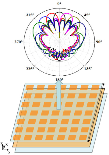
3.1. Beam Steering

In general, a phase difference between adjacent elements in the array produces a sloped isophase plane, which deflects the beam and realizes beam steering. The beam deflection angle is proportional to the phase difference, which could be described by the generalized Snell’s law [37,38]:
sin ( θ t ) n t sin ( θ t ) n i = λ 0 2 π d φ d x
where θ i and θ t are the incident angle and refractive angle, respectively. ni and nt are the refractive indexes of the incident and refractive region, and ni = nt = 1 in our case. φ is the abrupt phase introduced at the interface. Equation (1) implies that the refracted beam can have an arbitrary direction, provided that a suitable constant gradient of phase discontinuity along the interface is introduced. According to the simulations above and Equation (1), it is known that the designed 7 elements can be rearranged in a period, actively achieving three phase orders and beam steering angles. Table 2 shows the distribution of elements and their corresponding phases with different phase orders. The phase order N indicates a phase gradient of N × 2π/7, which could be actively controlled by choosing the feeding lines.
Considering both the size of the structure and the number of phase gradients, a patch array with 7 × 7 antenna elements is adopted and schematically shown in Figure 4. In this array, the desired phase gradient is oriented along the x-direction. Meanwhile, the phase remains constant along the y-direction. In addition, this patch array may obtain a beam steering order from −3rd to 3rd due to the symmetry of the proposed structure. Here, we only consider a one-dimensional case scanning in the x-direction. It can be easily predicted that the designed patch array may achieve a two-dimensional beam scanning by engineering the feeding network along both x- and y-directions (not shown here).
Figure 5a shows the simulated radiation patterns of the electric field in the x-z plane from −3rd to −3rd phase gradient orders. It can be seen that the designed patch array produced directive beams with a wide scanning angle of 110°, rotating from −55°, −34°, 17°, 0°, 17°, 34°, to 55°, when the phase gradient was tuned as −6π/7, −4π/7, −2π/7, 0, 2π/7, 4π/7, and 6π/7, respectively. These scanning angles agree well with the theoretical results obtained by Equation (1). In addition, the gains of all the arrays exceeded 20 dB, verifying the good performance of the designed tunable beam steering. To further demonstrate the accuracy of the beam steering, we plot in Figure 5b the near field distributions of the electric field in the x-z plane of the designed patch array. The simulation results of the engineered wavefront propagated towards oblique angles of −55°, −34°, −17°, 0°, 17°, 34°, 55°, when the phase gradient was tuned to be −6π/7, −4π/7, −2π/7, 0, 2π/7, 4π/7, and 6π/7, respectively. Overall, from Figure 5, we see that the proposed actively tunable patch array can effectively control the radiation pattern.

3.2. Beam Focusing

The other important issue of wavefront control equipment is beam focusing, which has many practical applications. The results above have already demonstrated the ability of the designed elements to actively manipulate the phase of the radiation field. According to the Huygens-Fresnel principle, we can also obtain beam focusing by engineering the phase distribution in the way of focusing formula, which can be described by the following equation [39]:
φ ( r ) = 2 π λ ( f r 2 + f 2 ) ,
where f is the focal length of the array, λ is the wavelength of electromagnetic wave, r is the distance vector between the array elements and the focal point, and φ ( r ) is the phase profile of each array element. Equation (2) implies the required phase of each array element for beam focusing at a certain point. In our scheme, we chose to focus at a distance of five times the wavelength from the center of the patch array, which means f = 5 mm. In addition, we planned to manipulate the focus at different positions in the y-z plane for demonstrating the good performance of the tenability. When r and f are determined, the corresponding phase value of each element can be obtained by substituting them into Equation (1), as shown in Figure 6(a1–a3). The electric field distributions in the y-z plane are plotted in Figure 6(b1–b3). It is not difficult to observe the focusing of the radiation field at the distance of f = 5 mm. In addition, the focus is actively tuned on the left, middle, and right sides of the y-z plane. The simulated electric field intensity at the focus in the x-y plane is shown in Figure 6(c1–c3), further validating the active tenability of the focusing property. Figure 6(d1–d3) plot the electric field intensity extracted along the red lines in Figure 6(b1–b3), respectively. The focus phenomenon is significant even though the sidelobe level is similar to the main focusing peak. We have to say that the focusing property is not good enough due to the discontinuous phase distributions, as anyone can be seen from Figure 6(a1–a3). Nevertheless, this work considers the tunable manipulation of the wavefront which has been successfully demonstrated. A better focusing property could be achieved by designing a more accurate phase gradient by a better manipulation of the feeding lines of the unit element.

3.3. Generation of Multi-Order Orbital Angular Momentum Vortex Beams

The OAM vortex beam has a helical wavefront and carries an orbital angular momentum of l, which is related to many intriguing applications such as communication and imaging. Here, the topological charge l is the number of twists of the wavefront from 0 to 2π. the OAM vortex beam with a topological charge of l = 1 can be generated by a spiral phase profile ranging from 0 to 2π with a gradient phase increment along the azimuthal direction [40]. A circular array with continuous gradient phase increment and uniform amplitude is an ideal scheme to generate an OAM wave. However, the continuous phase profile is not easy to achieve in both simulation and experiment. Therefore, it is common to divide the circle into several uniform sectors. In our design, only the circular region of the 7 × 7 array was excited to generate an OAM vortex beam. In exact words, three cells at each corner of the 7 × 7 array were not excited, and the other 37 cells were excited. For our designed radiation elements, the phase coverage from 0 to 2Nπ could be achieved and the phase increment was 2Nπ/7, where N = 1, 2, 3. In other words, we may actively achieve an OAM vortex beam with a topological charge of l = 1, 2, 3 by using the proposed structures.
For demonstration, we manipulated the unit elements to uniformly change the phase along the azimuthal direction over 0–2π. The simulated electric field intensity is shown in Figure 7a and the amplitude null in OAM mode can be clearly observed at the center, illustrating the good performance of the design. The corresponding spatial phase pattern with an evident abrupt phase jump from −π to π within a 2π azimuthal range is shown in Figure 7d, which indicates that the topological charge of the patch array was 1. In addition, the generated OAM vortex waves can be actively tuned to the cases with larger topological charges by using higher-order phase gradients. When the second-order phase gradient of 2Nπ/7 was adopted, the phase of the radiation field varied from 0 to 4π along the azimuthal direction, therefore generating the OAM vortex beam with a topological charge of 2. Figure 7b shows the electric field intensity with the characteristic intensity minimum at the center, and the corresponding phase distribution in Figure 7e possesses two evident abrupt phase jumps from −π to π. In addition, we can also generate an OAM vortex beam with a topological charge of 3 with the same approach. Figure 7c,f illustrates the simulated electric field intensity and phase distribution, further verifying the tunable performance of the proposed method.

3.4. Discussion

The above numerical results, including beam steering, focusing and generation of OAM vortex beams, could successfully demonstrate the validation of the proposed method. It is because the used FDTD method is a full-wave simulation algorithm, which is widely accepted in the related research fields of electromagnetic theory from visible to the microwave region [36]. From an experimental point of view, 7 × 7 patch elements, phase shifters, bias voltage control circuits operating at high frequency and vector network analyzer are required. By adjusting the bias voltage of the diode printed on the microstrip plate phase shifter, the states of the switch can be controlled. As a result, the phase shift can be achieved by controlling current to pass through microstrip lines with different lengths. The signal from the vector network analyzer is connected to the patch unit through the phase shifter. By adjusting the phase through the method mentioned above, beam scanning, focusing and generation of OAM wave can be obtained.

4. Conclusions

In conclusion, we have proposed a patch array with tunable functions of beam steering, focusing and generation of OAM vortex beams at the working frequency of 300 GHz. The patch array consists of 7 × 7 elements and the beam scanning angle could reach 110° by designing a 3rd order array. By actively adjusting the phase of the array elements, we have achieved beam focusing at different positions with a distance of five times the wavelength from the patch array. In addition, we also designed the patch array to generate vortex beams with multiple topological charges by high-order phase modes. These capabilities will make the patch array has a good prospect of applications.

Author Contributions

Conceptualization, Z.Y. and Q.Z.; methodology, K.G.; software, Q.Z. and K.G.; writing—original draft preparation, Z.Y and Q.Z.; writing—review and editing, Z.G., and K.G.; supervision, Z.G.; funding acquisition, Z.G.

Funding

National Natural Science Foundation of China (61775050, 11804073), Natural Science Foundation of Anhui Province, China (1808085QA21), Fundamental Research Funds for the Central Universities (PA2019GDZC0098, JZ2018HGBZ0309, JZ2018HGTB0240).

Conflicts of Interest

The authors declare no conflict of interest.

References

  1. Suedan, G.A.; Jull, E.V. Beam Diffraction by Planar and Parabolic Reflectors. IEEE Trans. Antennas Propag. 1991, 39, 521–527. [Google Scholar] [CrossRef]
  2. Yurduseven, O.; Yurduseven, O. Compact parabolic reflector antenna design with cosecant-squared radiation pattern. In Proceedings of the 2011 IEEE Microwaves, Radar and Remote Sensing Symposium, Kiev, Ukraine, 25–27 August 2011; pp. 382–385. [Google Scholar]
  3. Cheng, Y.J.; Hong, W.; Wu, K. Millimeter-wave substrate integrated waveguide multibeam antenna based on the modified R-KR lens. In Proceedings of the 2008 IEEE MTT-S International Microwave Symposium Digest, Atlanta, GA, USA, 15–20 June 2008; pp. 703–706. [Google Scholar]
  4. Mehmood, A.; Karabey, O.H.; Ayluctarhan, M.; Zheng, Y.L.; Braun, H.; Hovhannisyan, M.; Letz, M.; Jakoby, R. Dielectric resonator antenna phased array with liquid crystal based phase shifters. In Proceedings of the 8th European Conference on Antennas and Propagation IEEE (EuCAP 2014), The Hague, The Netherlands, 6–11 April 2014; pp. 2436–2439. [Google Scholar]
  5. Mehmood, A.; Karabey, O.H.; Jakoby, R. Dielectric Resonator Antenna with Tilted Beam. IEEE Antennas Wirel. Propag. Lett. 2017, 16, 1119–1122. [Google Scholar] [CrossRef]
  6. Karabey, O.H.; Mehmood, A.; Ayluctarhan, M.; Braun, H.; Letz, M.; Jakoby, R. Liquid Crystal Based Phased Array Antenna with Improved Beam Scanning Capability. Electron. Lett. 2014, 50, 426–428. [Google Scholar] [CrossRef]
  7. Perez-Palomino, G.; Baine, P.; Dickie, R.; Bain, M.; Encinar, J.A.; Cahill, R.; Barba, M.; Toso, G. Design and Experimental Validation of Liquid Crystal-Based Reconfigurable Reflectarray Elements with Improved Bandwidth in F-Band. IEEE Trans. Antennas Propag. 2013, 61, 1704–1713. [Google Scholar] [CrossRef]
  8. Doumanis, E.; Dickie, R.; Baine, P.; Perez-Palomino, G.; Cahill, R.; Goussetis, G.; Encinar, J.A.; Barba, M.; Christie, S.; Mitchell, N. Nematic Liquid Crystals for Reconfigurable Millimeter Wavelength Antenna Technology. In Proceedings of the 2013 7th European Conference on Antennas and Propagation IEEE (EuCAP), Gothenburg, Sweden, 8–12 April 2013; pp. 1791–1792. [Google Scholar]
  9. Perez-Palomino, G.; Encinar, J.A.; Barba, M.; Carrasco, E. Design and Evaluation of Multi-Resonant Unit Cells Based on Liquid Crystals for Reconfigurable Reflectarrays. IET Microw. Antennas Propag. 2012, 6, 348–354. [Google Scholar] [CrossRef]
  10. Perez-Palomino, G.; Florencio, R.; Encinar, J.A.; Braba, M.; Dickie, R.; Cahill, R.; Baine, P.; Bain, M.; Boix, R.R. Accurate and Efficient Modeling to Calculate the Voltage Dependence of Liquid Crystal-Based Reflectarray Cells. IEEE Trans. Antennas Propag. 2014, 62, 2659–2668. [Google Scholar] [CrossRef] [Green Version]
  11. Perez-Palomino, G.; Barba, M.; Encinar, J.A.; Cahill, R.; Dickie, R.; Baine, P.; Bain, M. Design and Demonstration of an Electronically Scanned Reflectarray Antenna at 100 GHz Using Multiresonant Cells Based on Liquid Crystals. IEEE Trans. Antennas Propag. 2015, 63, 3722–3727. [Google Scholar] [CrossRef] [Green Version]
  12. Florencio, R.; Encinar, J.A.; Boix, R.R.; Perez-Palomino, G. Dual-Polarisation Reflectarray Made of Cells with Two Orthogonal Sets of Parallel Dipoles for Bandwidth and Cross-Polarisation Improvement. IET Microw. Antennas Propag. 2014, 8, 1389–1397. [Google Scholar] [CrossRef]
  13. Karabey, O.H.; Gaebler, A.; Strrunck, S.; Jakoby, R. A 2-D Electronically Steered Phased-Array Antenna with 2×2 Elements in LC Display Technology. IEEE Trans. Microw. Theory Tech. 2012, 60, 1297–1306. [Google Scholar] [CrossRef]
  14. Zhao, Y.Z.; Huang, C.; Qing, A.Y.; Luo, X.G. A Frequency and Pattern Reconfigurable Antenna Array Based on Liquid Crystal Technology. IEEE Photonics J. 2017, 9, 1–7. [Google Scholar] [CrossRef]
  15. Zhang, T.; Li, L.M.; Xia, H.Y.; Ma, X.J.; Cui, T.J. A Low-Cost and High-Gain 60-GHz Differential Phased Array Antenna in PCB Process. IEEE Trans. Compon. Packag. Manuf. Technol. 2018, 8, 1281–1291. [Google Scholar] [CrossRef]
  16. Ma, S.; Zhang, S.Q.; Ma, L.Q.; Meng, F.Y.; Erni, D.; Zhu, L.; Fu, J.H.; Wu, Q. Compact Planar Array Antenna with Electrically Beam Steering from Backfire to Endfire Based on Liquid Crystal. IET Microw. Antennas Propag. 2018, 12, 1140–1146. [Google Scholar] [CrossRef]
  17. Guo, Z.Y.; Xu, H.S.; Guo, K.; Shen, F.; Zhou, H.P.; Zhou, Q.F.; Gao, J.; Yin, Z.P. High-efficiency visible transmitting polarizations devices based on the GaN metasurface. Nanomaterials 2018, 8, 333. [Google Scholar] [CrossRef] [PubMed]
  18. Zhou, H.P.; Chen, L.; Shen, F.; Guo, K.; Guo, Z.Y. Broadband Achromatic Metalens in the Midinfrared Range. Phys. Rev. Appl. 2019, 11, 024066. [Google Scholar] [CrossRef]
  19. Wang, J.J.; Zhou, J.; Guo, K.; Shen, F.; Zhou, Q.F.; Yin, Z.P.; Guo, Z.Y. High-efficiency terahertz dual-function devices based on the dielectric metasurface. Superlattices Microstruct. 2018, 120, 759–765. [Google Scholar] [CrossRef]
  20. Guo, K.; Xu, H.S.; Peng, Z.Y.; Liu, X.; Guo, Z.Y. High-efficiency full-vector polarization analyzer based on GaN metasurface. IEEE Sens. J. 2019, 19, 3654–3659. [Google Scholar] [CrossRef]
  21. Bogosanovic, M.; Williamson, A.G. Microstrip Antenna Array with a Beam Focused in The Near-Field Zone for Application in Noncontact Microwave Industrial Inspection. IEEE Trans. Instrum. Meas. 2007, 56, 2186–2195. [Google Scholar] [CrossRef]
  22. Stephan, K.D.; Mead, J.; Pozar, D.M.; Wang, L.Y.; Pearce, J.A. A Near Field Focused Microstrip Array for a Radiometric Temperature Sensor. IEEE Trans. Antennas Propag. 2007, 55, 1199–1203. [Google Scholar] [CrossRef]
  23. Durney, C.H.; Iskander, M.F. Antennas for Medical Applications. In Antenna Handbook; Springer: Boston, MA, USA, 1988; pp. 596–654. [Google Scholar]
  24. Shen, F.; Mu, J.N.; Guo, K.; Wang, S.M.; Guo, Z.Y. Generation of continuously-variable-mode vortex electromagnetic waves with three-dimensional helical antenna. IEEE Antennas Wirel. Propag. Lett. 2019, 18, 1091–1095. [Google Scholar] [CrossRef]
  25. Wang, L.L.; Chen, H.Y.; Guo, K.; Shen, F.; Guo, Z.Y. An Inner-and Outer-Fed Dual-Arm Archimedean Spiral Antenna for Generating Multiple Orbital Angular Momentum Modes. Electronics 2019, 8, 251. [Google Scholar] [CrossRef]
  26. Deng, C.J.; Chen, W.H.; Zhang, Z.J.; Li, Y.; Feng, Z.H. Generation of OAM Radio Waves Using Circular Vivaldi Antenna Array. Int. J. Antennas Propag. 2013, 2013, 847859. [Google Scholar] [CrossRef]
  27. Li, H.; Kang, L.; Wei, F.; Cai, Y.M.; Yin, Y.Z. A Low-Profile Dual-Polarized Microstrip Antenna Array for Dual-Mode OAM Applications. IEEE Antennas Wirel. Propag. Lett. 2017, 16, 3022–3025. [Google Scholar] [CrossRef]
  28. Bai, X.D.; Liang, X.L.; Sun, Y.T.; Hu, P.C.; Yao, Y.; Wang, K.; Geng, J.P.; Jin, R.H. Experimental Array for Generating Dual Circularly-Polarized Dual-Mode OAM Radio Beams. Sci. Rep. 2017, 7, 40099. [Google Scholar] [CrossRef] [PubMed]
  29. Guo, Z.Y.; Wang, Z.K.; Dedo, M.I.; Guo, K. The Orbital Angular Momentum Encoding System with Radial Indices of Laguerre–Gaussian Beam. IEEE Photon. J. 2018, 10, 1–11. [Google Scholar] [CrossRef]
  30. Wang, Z.K.; Dedo, M.I.; Guo, K.; Zhou, K.Y.; Shen, F.; Sun, Y.X.; Liu, S.T.; Guo, Z.Y. Efficient recognition of the propagated orbital angular momentum modes in turbulences with the convolutional neural network. IEEE Photon. J. 2019, 11, 7903614. [Google Scholar] [CrossRef]
  31. Feng, Z.K.; Wang, X.Y.; Dedo, M.I.; Guo, K.; Shen, F.; Kai, C.H.; Guo, Z.Y. High-density Orbital Angular Momentum mode analyzer based on the mode converters combining with the modified Mach–Zehnder interferometer. Opt. Commun. 2019, 435, 441–448. [Google Scholar] [CrossRef]
  32. Kai, C.H.; Feng, Z.K.; Dedo, M.I.; Huang, P.; Guo, K.; Shen, F.; Gao, J.; Guo, Z.G. The performances of different OAM encoding systems. Opt. Commun. 2019, 430, 151–157. [Google Scholar] [CrossRef]
  33. Nikfalazar, M.; Kohler, C.; Wiens, A.; Mehmood, A.; Sohrabi, M.; Maune, H.; Binder, J.R.; Jakoby, R. Beam steering phased array antenna with fully printed phase shifters based on low-temperature sintered BST-composite thick films. IEEE Microw. Wirel. Compon. Lett. 2016, 26, 70–72. [Google Scholar] [CrossRef]
  34. Technology Solutions for THz Electronics, Schottky Zero-Bias Diode, 3DSF5. Available online: https://www.acst.de/downloads/ACST_Datasheet_3DSF5.pdf (accessed on 3 July 2019).
  35. Timsina, R.L.; Messner, R.A.; Kubwimana, J.L. A compact design of switched line phase shifter for a microstrip phased array antenna. In Proceedings of the 2017 Progress in Electromagnetics Research Symposium-Fall (PIERS-FALL), Singapore, 19–22 November 2017; pp. 1839–1844. [Google Scholar]
  36. Kunz, K.S.; Luebbers, R.J. The Finite Difference Time Domain Method for Electromagnetics, 1st ed.; CRC Press: Boca Raton, FL, USA, 1993; pp. 1–101. [Google Scholar]
  37. Yu, N.F.; Genevet, P.; Kats, M.A.; Aieta, F.; Tetienne, J.P.; Capasso, F.; Gaburro, Z. Light propagation with phase discontinuities: Generalized laws of reflection and refraction. Science 2011, 334, 333–337. [Google Scholar] [CrossRef]
  38. Li, R.Z.; Guo, Z.Y.; Wang, W.; Zhang, J.R.; Zhang, A.J.; Liu, J.L.; Qu, S.L.; Gao, J. High-efficiency cross polarization converters by plasmonic metasurface. Plasmonics 2015, 10, 1167–1172. [Google Scholar] [CrossRef]
  39. Zuo, H.J.; Choi, D.Y.; Gai, X.; Ma, P.; Xu, L.; Neshev, D.N.; Zhang, B.P.; Barry, L.D. High-Efficiency All-Dielectric Metalenses for Mid-Infrared Imaging. Adv. Opt. Mater. 2017, 5, 1700585. [Google Scholar] [CrossRef]
  40. Akram, M.R.; Bai, X.D.; Jin, R.H.; Vandenbosch, G.A.E.; Premaratne, M.; Zhu, W. Photon spin Hall effect based ultra-thin transmissive metasurface for efficient generation of OAM waves. IEEE Trans. Antennas Propag. 2019, 67, 4650–4658. [Google Scholar] [CrossRef]
Figure 1. (a) Geometrical construction of the element. (b) Geometrical construction of the phase shifter.
Applsci 09 02949 g001
Figure 2. S-parameters of radiation patch obtained from each arm of feeding line in (a) element 2 (b) element 3 (c) element 4 (d) element 5 (e) element 6 (f) element 7.
Applsci 09 02949 g002
Figure 3. Phase of radiation patch obtained from each arm of feeding line in (a) element 2 (b) element 3 (c) element 4 (d) element 5 (e) element 6 (f) element 7.
Applsci 09 02949 g003
Figure 4. Geometrical construction of the patch array.
Applsci 09 02949 g004
Figure 5. (a) Radiation patterns of patch array in the x-z plane with phase gradients of −6π/7 (green line), −4π/7 (blue line), −2π/7 (red line), 0 (black line), 2π/7 (pink line), 4π/7 (olive green line), and 6π/7 (navy line) and (b) the corresponding electric field distribution in the x-z plane when the beam steering angle was 55°, 34°, 17°, 0°, 17°, 34°, and 55°, respectively.
Applsci 09 02949 g005
Figure 6. The phase distribution for beam focusing on the (a1) left, (a2) middle and (a3) right sides of the y-z plane. (b1b3) and (c1c3) show the electric field intensity distribution focusing on the left, middle and right sides in the y-z and x-y plane, respectively. (d1d3) The extracted field intensities along the red line in (b1b3).
Applsci 09 02949 g006
Figure 7. (ac) The electric field intensity distributions and (df) the phase wavefronts of the generated OAM vortex beams with a topological charge of l = 1, 2, 3 based on the patch array with different order phase gradient.
Applsci 09 02949 g007
Table 1. Parameters of the element and phase shifter (unit: mm).
Parameterlpwppw1l1l2l3l4
Element 20.3030.39210.1430.040.090.140.02
Element 30.3030.39210.1430.090.190.290.02
Element 40.3030.39210.1430.140.290.090.02
Element 50.3030.39210.1430.190.040.240.02
Element 60.3030.39210.1430.240.140.040.02
Element 70.3030.39210.1430.290.240.190.02
Table 2. The phase distribution of array elements under different phase gradients (unit: 2π/7 rad).
Element1234567
Phase Order
00000000
10123456
20246135
30362514

