Article

Fiber Bragg Gratings Based Cyclic Strain Measuring of Weld Toes of Cruciform Joints

1
Key Laboratory of Metallurgical Equipment and Control Technology, WUST, Ministry of Education, Wuhan 430081, China
2
Hubei Key Laboratory of Mechanical Transmission and Manufacturing Engineering, WUST, Wuhan 430081, China
*
Author to whom correspondence should be addressed.
Appl. Sci. 2019, 9(14), 2939; https://doi.org/10.3390/app9142939
Submission received: 27 June 2019 / Revised: 19 July 2019 / Accepted: 22 July 2019 / Published: 23 July 2019
(This article belongs to the Special Issue Selected Papers from IMETI 2018)

Abstract

:
The real weld toe geometry is generally not mathematically perfect, resulting in obvious stress concentration effects, both on the weld section and along the longitudinal direction of the weld toe. The true stress-strain state at the local weld toe directly affects the fatigue performance and behavior of the welded structure. Therefore, a Fiber Bragg Grating (FBG) sensor based method for testing the cyclic strain at the weld toe was proposed. Cruciform welded joints were fabricated as specimens on which FBG sensors were arranged at several characteristic points along the weld toe curve. Strains at all the characteristic points under cyclic tensile load were measured and recorded, which showed the proposed measuring method could accurately obtain the complete local strain time histories along the weld toe. The strain time histories clearly reflected the cyclic hardening phenomenon in the early stage and the plastic yielding phenomenon in the final stage. Furthermore, based on the cyclic stress-strain constitutive model of the weld material, the stress-strain response curves of all the characteristic points were drawn. Combined with the fatigue fracture morphology, the mechanism of the unsynchronized initiation of the multiple cracks in the weld toe was investigated.

1. Introduction

Welding is one of the most common methods in manufacturing for the joining components. It has the main advantages of simple structure, easy process, low costs, superior performance and high reliability. Welded structures are widely used in industries, bridges, buildings, mechanical equipment and so on. Engineering application shows that welded structures are prone to develop fatigue cracks under cyclic loads. Once the cracks appear and the welded structure can’t be repaired in time, it will probably cause vital damage. A great deal of research [1,2,3,4,5] has shown that the fatigue performance of welded structures mainly depends on the type of weld joints and the loads. Fatigue cracks often appear in the local position of the weld, especially at the stress concentration position along the weld toe. Therefore, it is significant to understand the stress-strain state and its response behavior at the weld toe of the welded joint to accurately predict the fatigue life of the welded structure, enhancing the fatigue performance of the welded structure and finally improving the welding procedure.
For welded joints, the stress-strain state on the weld section is usually described by the stress concentration factor (SCF). Some researchers [6,7,8] have employed theoretical and numerical analysis methods to investigate the geometric parameters for typical welded joints and proposed a variety of formulas to relate the key geometric parameters (such as weld inclination angle, θ , fillet leg length,   l , weld toe radius,   ρ and plate thickness,   t , etc.) with SCF. Considering the different effects of different welded joints type on SCF, a variety of fatigue life prediction methods have been proposed for cruciform joints [9,10,11], T-joints [12,13], lap joints [14,15] and butt joints [16,17], respectively. Other researchers have paid attention to some special issues such as single-sided and double-sided welds [18], load-carrying welds and non-load-carrying welds [19,20], uniaxial tensile and bending loads [21,22], weld penetration ratio [23], etc. These investigations not only verified further that the weld toe was the weakest position of the fatigue damage for welded structures but also revealed that the local stress-strain state at the weld toe was affected by various factors including geometry, load, material and its microstructure. However, the above investigations only focused on the SCF effect on the weld section. Hou [24] used 3D laser scanning technology to acquire the real weld toe geometry of some welded specimens, by which Finite Element Analysis (FEA) models were established, and then the SCF along the weld toe was computed. The results showed that the longitudinal discontinuities along the weld geometry also have significant influence on the fatigue performances of the weld joints.
In this context, measuring the stresses or strains at the weld toe directly became meaningful and challenging work, which was attempted by some researchers. Generally, stress signals in the mechanical properties testing for materials were obtained by the built-in force sensors of the testing machine, while strain signals were obtained by extensometers. Extensometers essentially get the average strain of the measured area, which cannot reflect the local characteristics. For welded joints, extensometers are difficult to fix on the proper weld region. Therefore, extensometers are not suitable for strain measurement of welded specimens. Recently, a new method called Digital Image Correlation (DIC) has been proposed in the field of strain measuring [25,26]. To some extent, this method can analyze the distribution gradient of stress and strain by digital image techniques. However, it is also not suitable for weld structures due to the complex surface topography on the weld. So, resistive strain gauge sensors are still widely used in strain testing for welded joints at present. Otegui [27] arranged several strain gauges near the weld toe along the longitudinal direction of the weld and monitored the strain time history. The initiation time of the weld toe crack was discussed by analyzing the strain signals, gauges position and the crack morphology. Lukashevich [28] used strain gauges to measure the strain for the low-carbon steel welded specimen under cyclic loads. Amplitude difference technology and phase difference technology were employed to monitor the initiation and growth of the subcritical fatigue cracks. These investigations only captured the initiation time of the fatigue crack based on the changes of the strain signal but did not reveal the stress-strain behavior of the weld toe deeply. Takeuchi [29,30] arranged two strain gauges vertical to the weld line with two different distances from the weld and calculated the hot-spot stress at the weld toe by linear extrapolation. Essentially, the hot-spot stress is a constructive stress parameter and cannot characterize the actual stress-strain state at the weld toe.
Due to inherent deficiencies such as zero drift, resistive strain gauges are generally used for static testing or short-time dynamic testing. There are some inevitable problems for the local strain measuring of the weld toe: (1) The weld toe curve does not have mathematical continuity and the SCF effect along the longitudinal direction of the weld toe is not uniformly distributed. Therefore, several resistive strain gauges are required to capture the characteristic strains along the weld toe. (2) Resistance strain gauges often have bases with non-negligible areas. Even if the gauge has adhered to the weld toe, the actual testing point is still at a certain distance from the actual weld toe point. Therefore, it is difficult to obtain the real strain at the weld toe point. (3) Due to SCF effect on the weld toe, even if the nominal stresses and strains usually obtained by strain gauges are in linear elastic phase, the actual local stresses and strains at the weld toe points may probably excess the plastic phase. So sometimes the stresses and strains obtained by strain gauges are unable to characterize the actual stresses and strains state along the weld toe, which are vital to the life prediction of welded joints. (4) In fatigue testing, specimens are subjected to cyclic loads. The material of the structure has a completely different stress-strain response behavior from that under monotonic loads. In a word, resistive strain gauges are not practical to measure the cyclic strain for welded joints.
Recently, optical fiber based sensing technology has gained a growing amount of attention from researchers and engineers, among which FBG sensors are widely used in structural health monitoring (SHM) due to their unique advantages such as a small size, light weight, embedding capability, immunity to corrosion and electromagnetic interference [31,32,33,34,35]. Aiming at the main problems in this investigation, a measuring method based on FBG was proposed to acquire the local cyclic strains along the weld toe of welded joints. Several FBG sensors were fabricated at multiple characteristic points along the weld toe on the thin plate of the cruciform joints. Fatigue test under cyclic tensile load was conducted, and the strains at each characteristic point were recorded in real-time. Based on the stress-strain constitutive model under the cyclic load of the weld material, the stress-strain response curves were drawn, and the hysteresis loops were analyzed. Finally, the weld toe geometry and fatigue fracture morphology were employed together to reveal the mechanism of weld toe crack initiation.

2. Theoretical Context

2.1. SCF of Welds

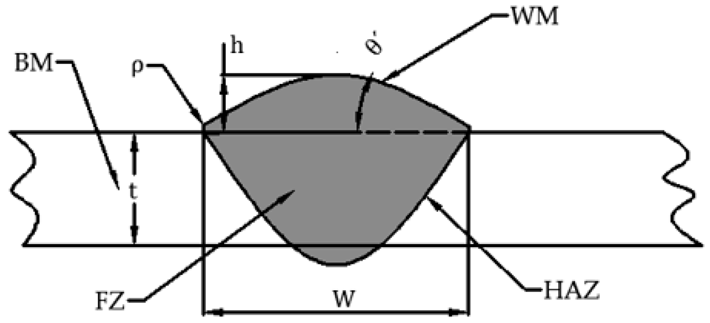
The formation of welded joints is the way in which two or more pieces meet together by the welding process. They are generally made of base metal (BM), weld metal (WM), fusion zone (FZ) and heat affected zone (HAZ). Welded joints experience a series of complicated processes such as local heating, metal melting and solidification, etc., which result in a region with heterogeneous ingredients, organization and mechanical properties.
According to the geometry of the weld, different welded joints have distinct SCF degrees. If the nonlinear plasticity is considered, stress and strain have different SCF, which are described as follows:
S C F σ = σ max σ n
S C F ε = ε max ε n
where S C F σ is the stress concentration factor, S C F ε is the strain concentration factor,   σ max is the maximum stress, σ n is the nominal stress, ε max is the maximum strain and ε n is the nominal strain.
In the research of fatigue fields, stress range, or strain range is the much more important controlling parameter. As such, this paper defines corresponding SCF parameters as follows:
S C F Δ σ = Δ σ max Δ σ n
S C F Δ ε = Δ ε max Δ ε n
where S C F Δ σ is the stress range concentration factor, S C F Δ ε is the strain range concentration factor,   Δ σ max is the maximum stress range, Δ σ n is the nominal stress range, Δ ε max is the maximum strain range and Δ ε n is the nominal strain range.
There are two kinds of typical welded joints commonly used in engineering, which are fillet joints (as shown in Figure 1) and butt joint (as shown in Figure 2). Their stress SCF formulas are shown as Equations (5) and (6) [7].
S C F σ = 1 + 0.35 ( tan θ ) 1 4 [ 1 + 1.1 ( c / l ) 3 5 ] 1 2 ( t ρ ) 1 / 2
S C F σ = 1 + 0.27 ( tan θ ) 1 / 4 ( t ρ ) 1 / 2
where θ is the weld inclination angle, θ is the reinforcement angle, t is the plate thickness, l is the fillet leg length, ρ is the weld toe radius and c is the weld un-penetration size.
It can be seen from the above formulas that for fillet joints, S C F σ mainly depends on the weld inclination angle, the ratio of the weld un-penetration size to the fillet leg length and the ratio of the plate thickness to the weld toe radius. Smaller weld inclination angle, larger weld toe radius and larger fillet leg length will result in smaller SCF at the weld toe. For butt joints, S C F σ mainly depends on the reinforcement angle, θ , and the ratio of the plate thickness to the weld toe radius. With constant plate thickness and weld width, smaller reinforcement angle and larger weld toe radius will be helpful to decrease the SCF. Compared with butt joints, fillet joints usually have larger weld inclination angle, and the fillet leg length cannot be large without limitation due to the plate thickness. Therefore, the weld shape transition of fillet joints is much sharper, which is prone to produce severer SCF in the weld toe. On the contrary, the transition geometry of butt joints changes mildly and the SCF is small. Therefore, fillet joints are generally inferior to butt joints in their fatigue performances.
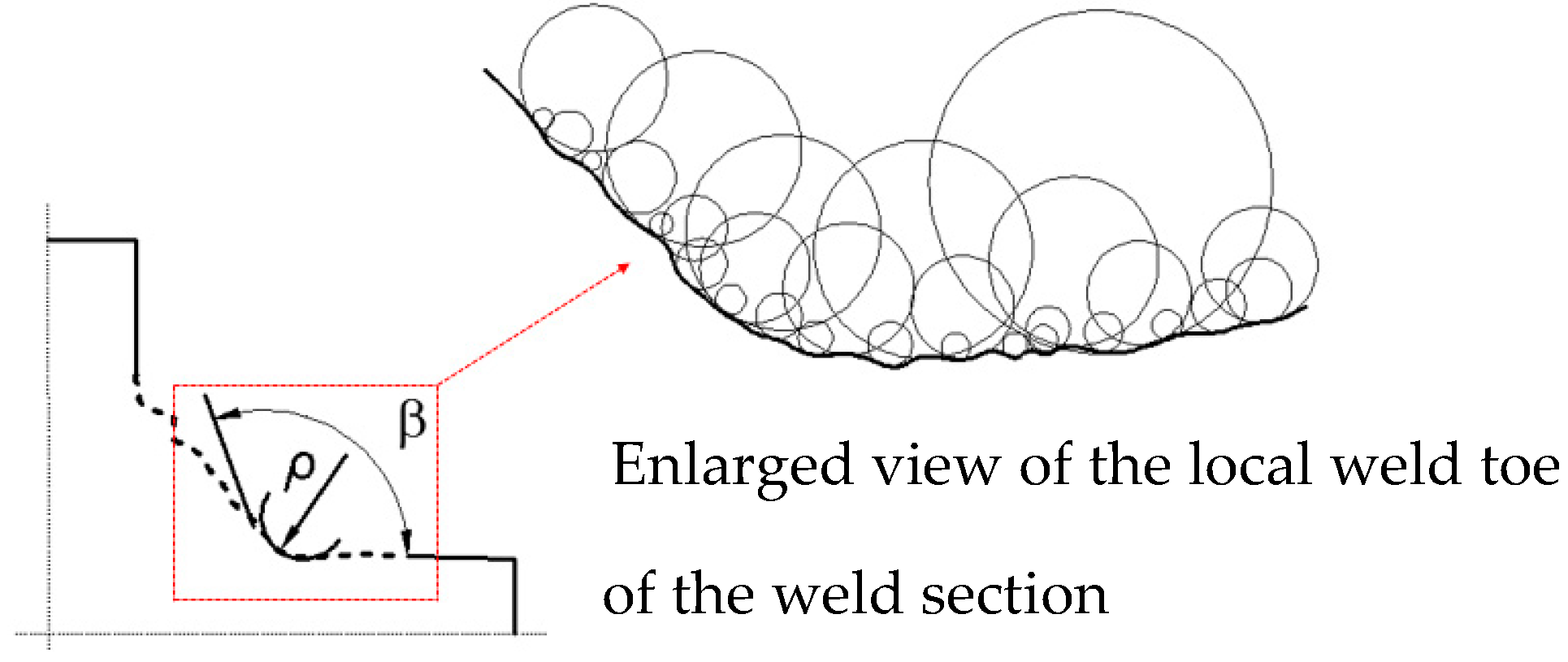
In fact, the transitional area of the weld toe is not an ideal rounded shape, as shown in Figure 3. It can be seen that the local weld toe of the real weld is often composed by a series of small arcs with different radii, in which the smaller radius is close to the dimension of surface roughness. Although the smaller arcs do not affect the overall geometry of the weld section, it has a key influence on SCF at the weld toe, unquestionably. In Equations (5) and (6), only an ideal arc radius is used to approximately characterize the weld toe radius, so both the stress state analysis of the weld toe and the fatigue life prediction of the welded joint are undoubtedly inaccurate.
In addition, due to the complicated process of solidification of weld metal, not only is the actual weld toe profile on the weld section is complex, but also the profiles on different weld sections are randomly variable along the longitudinal direction of the weld, which is more arresting to the weld toe curve. Initial weld defects such as undercuts, blow holes and slag inclusions usually appear on weld toes, which makes SCF along with weld toes more complicated and severe. Therefore, it is difficult to obtain sufficient accuracy by using constant weld geometry parameters to analyze and investigate the mechanical properties of actual welded structures in engineering application.

2.2. Cyclic Stress-Strain Response Behavior

Since the weld toe of welded joints has strong stress concentration effect, even if the nominal stress is in linear elastic phase, the actual stress and strain at the weld toe tend to be in plastic phase. Furthermore, compared with the elastic-plastic behavior under monotonic loading, the stress-strain response under cyclic loading is far more complicated.
Lots of fatigue tests concerning different metals have shown that the strain amplitude decreases gradually as the number of cycles increases, even if under the symmetrical loading with constant amplitude, which is called cyclic hardening. Conversely, some metals have the property of cyclic softening, which means strain amplitude increases with cycles increasing. Cyclic hardening and cyclic softening phenomena occur in not only strain-controlled tests but also stress-controlled tests. It is generally believed that the cyclic loading causes the metal to repeatedly undergo plastic deformation, resulting in some changes to the plastic flow characteristics of the material. Then the ability to resist deformation is enhanced or reduced, which reflects cyclic hardening or softening behavior. Commonly, cyclic hardening or softening happen in the early stage of cyclic loading, then it will disappear, and the stress amplitude or strain amplitude will stabilize gradually. Such behaviors can generally be described by cyclic stress-strain curve ( σ a   ε a curve) and hysteresis loop curve ( Δ σ Δ σ curve) [36].
The cyclic stress-strain curve can be expressed by Equation (7), which does not reflect the loading path. The hysteresis loop curve can cover this shortcoming and can be expressed by Equation (8).
ε a = ε e + ε p = σ a E + ( σ a K ) 1 / n
Δ ε = Δ ε e + Δ ε p = Δ σ E + 2 ( Δ σ 2 K ) 1 / n
where E is elastic modulus, K is cyclic strength coefficient, n is cyclic strain hardening exponent, ε a is strain amplitude, Δ ε is strain range, ε e is elastic strain, ε p is plastic strain, σ a is stress amplitude and Δ σ is stress range.
For welded joints, it is difficult to determine the actual stress at the weld toe by the force signals recorded by the testing machine. Therefore, strain signals at the weld toe are often obtained and used to calculate the corresponding stresses by combining Equations (7) and (8). Furthermore, the stress-strain response curve can be drawn. The computing procedure is as follows:
(1)
For the first loading cycle, σa is calculated according to εa by cyclic stress-strain curve (Equation (7)), in which εa is obtained from the strain testing data.
(2)
For other cycles, the hysteresis loop curve (Equation (8)) is used to calculate ∆σ according to ∆ε, in which ∆ε is obtained by rain flow counting for the strain testing data.
It is worth noting that when the strain reaches the same reversal point for the second time, a closed-loop will be formed, and the material memory effect should be introduced. Since the closed-loop does not affect the subsequent response process, stress and strain here should be calculated according to the previous loading path.

2.3. FBG Strain Sensor

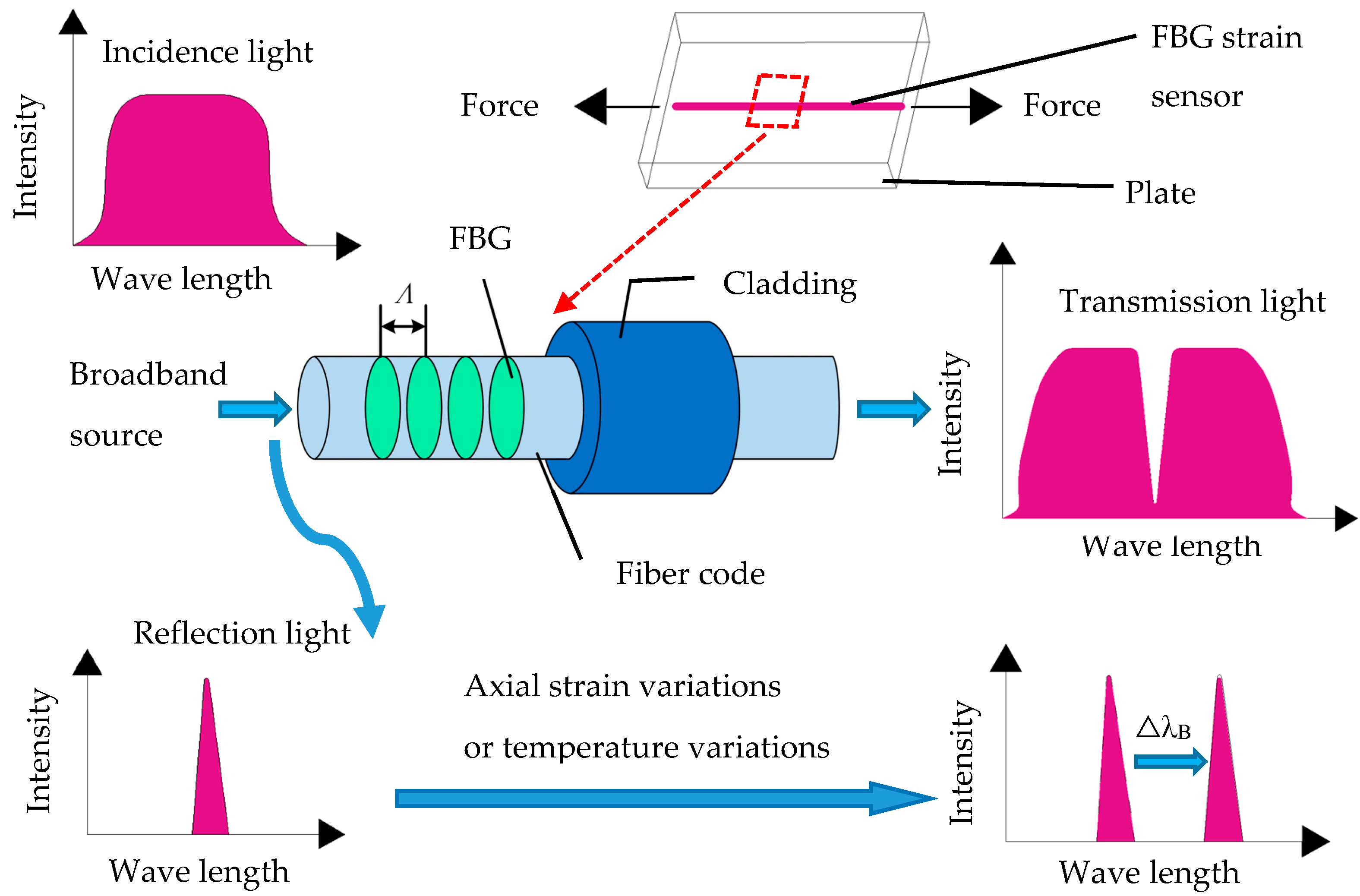
FBG is a periodic modulation of the index of refraction, which is inscribed into the core of a single-mode optical fiber [37]. Essentially, it works as a wavelength filter [38]. When a broadband light source is injected into the fiber, the FBG reflects a narrowband portion of the incident light with a specific wavelength, while the rest portion of the broadband light passes through, as shown in Figure 4.
Generally, the center wavelength of the reflection spectrum is called the Bragg wavelength (λB), which is correlated with the grating period (the distance between the consecutive grooves).
λ B = 2 n e f f Λ
where n e f f is the effective refractive index of the optical fiber, and Λ is the periodicity of the grating.
When the FBG is subjected to the external environment (e.g., strain and temperature), the grating period increases or decreases, and then the Bragg wavelength increases or decreases, respectively. Thus, the peak shift of the Bragg wavelength introduced by the strain variation ( Δ ε ) and the temperature variation ( Δ T ) can be expressed as:
Δ λ B λ B = ( 1 P e ) · Δ ε + ( α f + ξ ) · Δ T
where ΔλB is the shift of the Bragg wavelength, P e is the photo-elastic coefficient of the optical fiber, αf is the thermal expansion coefficient, ξ is the thermal-optic coefficient.
Typically, the fractional wavelength changes of λB are on the order of 10 pm/℃ and 1.2 pm/με for FBG with a center wavelength of 1550 nm [37]. So, the Bragg wavelength shift can be considered linear to the strain changes under constant temperature condition.
It should be noted that the optical fiber is a cylindrical filament composed of a cladding layer with an outer diameter of 125 μm and a core with a diameter of 9 μm. In order to enhance the mechanical properties of the optical fiber, a protective layer with a certain thickness may be coated outside the optical fiber. Therefore, the fiber (including grating) sectional dimension is about 0.25 mm, which is much smaller than the base size of the strain gauge. Therefore, it is possible to arrange multiple FBG sensors along the longitudinal direction of the weld toe. In addition, the optical fiber with secondary coating protection has good flexural deformation resistance and can be bonded along the weld toe transition arc even across the weld toe characteristic point. Since the wavelength signal collected by the FBG sensor is the maximum value of the Bragg wavelength in the grating, for the strain testing for weld joints, it can be considered that the obtained strain data is just the exact value at the most severe position ( which refers to weld toe local position) on the certain weld section. So, the FBG is a kind of ideal strain sensors which can be used for local strain measurement at the weld toe.

3. Test Configuration

3.1. Specimen Description

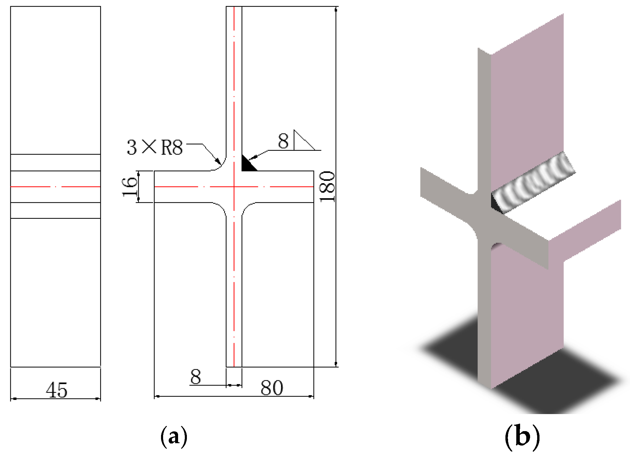
According to the SCF discussion of welded joints in the previous section, this paper selected a cruciform welded joint as the testing specimen, as shown in Figure 5. The base material of the specimen plates is Q345, which is low alloy steel widely used in China. The mechanical parameters and chemical compositions are shown in Table 1 and Table 2 [39,40].
In order to observe and monitor cracks easily in the testing process, only one weld was fabricated in the specimen. In detail, three corners of the specimens shown in Figure 5a were directly cut into a round shape, while the rest one was cut into a right-angled shape, which then was welded by manual arc welding. Both sides of the specimens were cut off to eliminate the unfavorable influence of the arc-starting segment and the arc-stopping segment of the weld. The metallographic examination was performed on the weld area of the cutting portion to avoid weld defects and incomplete penetration at the weld root. After the metallographic examination, the specimen was peened on the weld toe face in order to get rid of the residual stress. Finally, the surface of the specimens was polished with sandpaper.

3.2. Testing Points

The weld toe of the specimen is not an ideal line, resulting in the stress and strain state along the weld toe is variable under the same testing load, which finally affects the initiation sites of the weld toe cracks. It is necessary to determine the testing points where FBG will be fixed before testing.
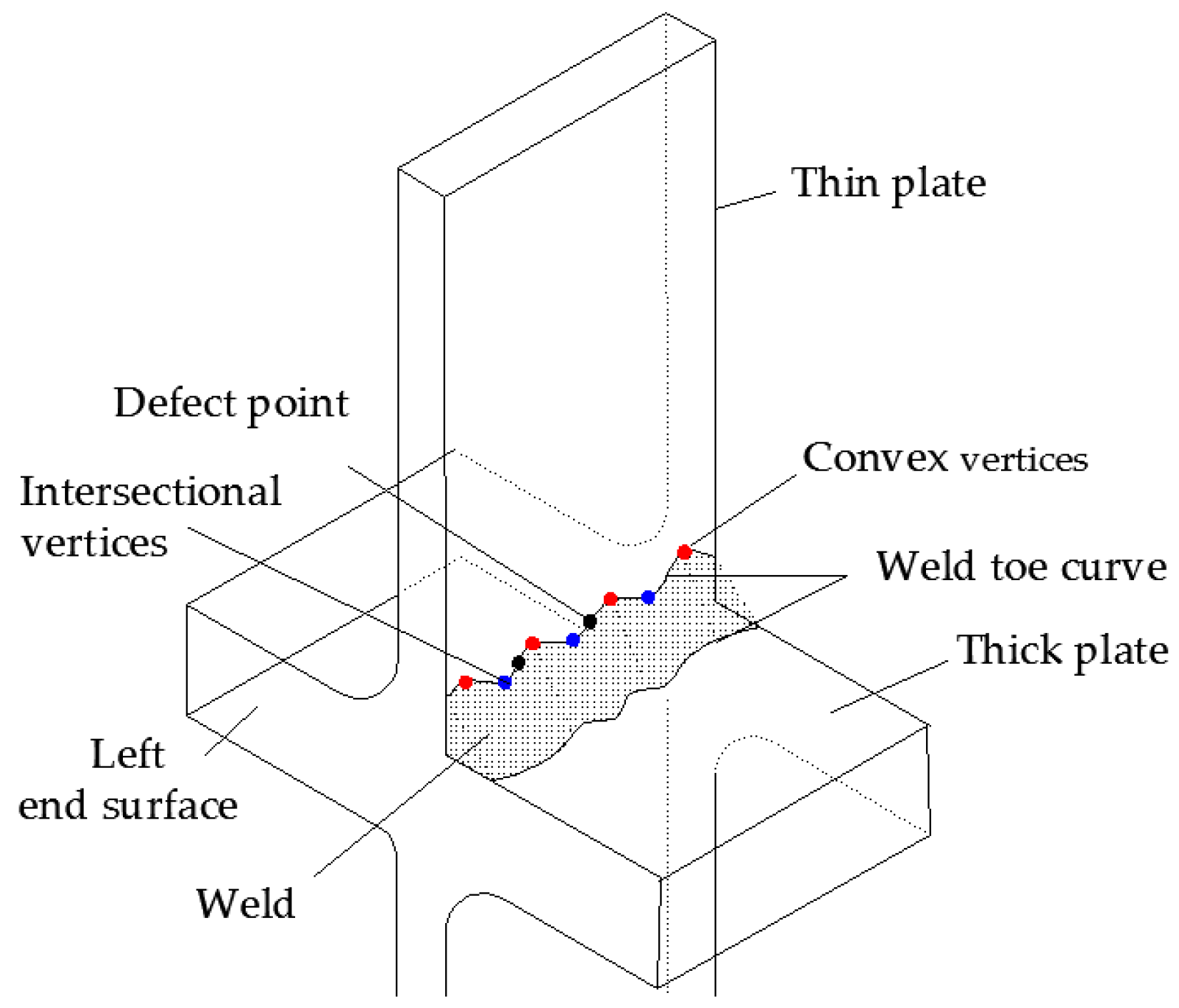
Based on some previous investigations, the weld toe can be simply described as a curve composed of some small arc segments, where convex vertices and intersectional vertices are the positions of discontinuity [41]. Together with obvious weld defect points, convex vertices and intersectional vertices can be defined as the characteristic points on the weld toe curve, which are potential positions to form micro-cracks, as shown in Figure 6. A series of morphologies of the characteristic weld sections were obtained by a CCD (Charge Coupled Device) digital microscope (LY, Qingyang district, Chengdu, China). Then the geometry parameters of those weld sections were measured based on digital image technology, and weld toe SCFs of corresponding sections were calculated by Equation (5). The measuring results and calculation results were shown in Table 3, where L is the distance from the left end surface to the corresponding section. Due to the full penetration of the specimen, the weld un-penetration size c is zero.
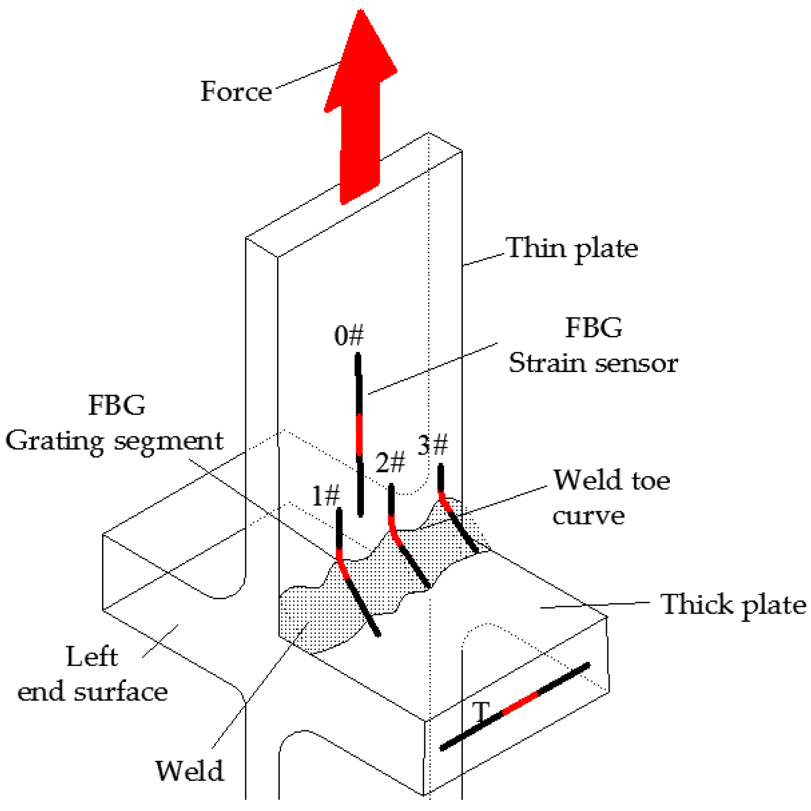
Table 3 shows that SCF at different weld toe characteristic points ranges from 1.90 to 2.06. Three points with largest SCF values were chosen as the main testing points (1#, 2#, 3#), at which strain time histories were recorded and analyzed. Another testing point (0#) was configured on the surface of the thin plate, which was used to verify the testing load. It is noteworthy that uniaxial tensile load was employed in the test (as shown in Figure 7), so only the axial strain needed to be measured. Therefore, FBG sensors at testing points 1#, 2#, 3# and 4# were fixed along the loading direction. Temperature compensation was realized by the testing point (T). In order to get rid of extra stress of the specimen, this FBG sensor was placed exactly in the middle of the thick plate and along the weld direction, which was vertical to the loading direction. All the five FBG sensors are single-mode optical fibers (SMF) with different grating Bragg wavelengths, as shown in Table 4. Each FBG sensor was connected to the respective channel of the demodulator. Detail arrangements are shown in Figure 7, where "L-" in Table 4 is defined as the distance between the testing point and the left end surface.
It should also be noted that, before fabricating the FBG sensors, the surface of the weld of the specimen should be cleaned with alcohol so as to get rid of stains on it. Due to good flexural resistance, the FBG can be fabricated across the characteristic points. In detail, one end of the FBG sensor was fixed on the surface of the thin plate, while the other end was fixed on the surface of the weld. When fabricating, make sure that the grating section of the FBG sensor was firmly attached on the surface of the weld toe. The fixing between FBG sensors and test points is realized by commercial adhesive (Structural Epoxy Adhesives DG-4). In order to prevent the FBG from breaking during the testing, secondary coating protection with acrylate material was employed after the grating was inscribed into the core of the optical fiber [38,42]. The coating is a layer of film with the same size with the original coating, that is, the outer diameter of 0.25 mm and the inner diameter of 0.125 mm. The coating work was done by a common fiber coating machine.

3.3. Test Procedure

The SDS-100 electro-hydraulic servo fatigue machine was used to conduct the fatigue test. The cyclic tensile force with constant amplitude 72 KN was applied to the thin plate. Cyclic ratio R was 0, and the loading frequency was 10 Hz. Since the load-carrying sectional area of the thin plate was 360 mm2, the maximum nominal testing stress was σn = 200 MPa. According to Table 1, E is 2.06 × 10⁵ MPa; the corresponding maximum nominal testing strain is εn = 970.8 με.
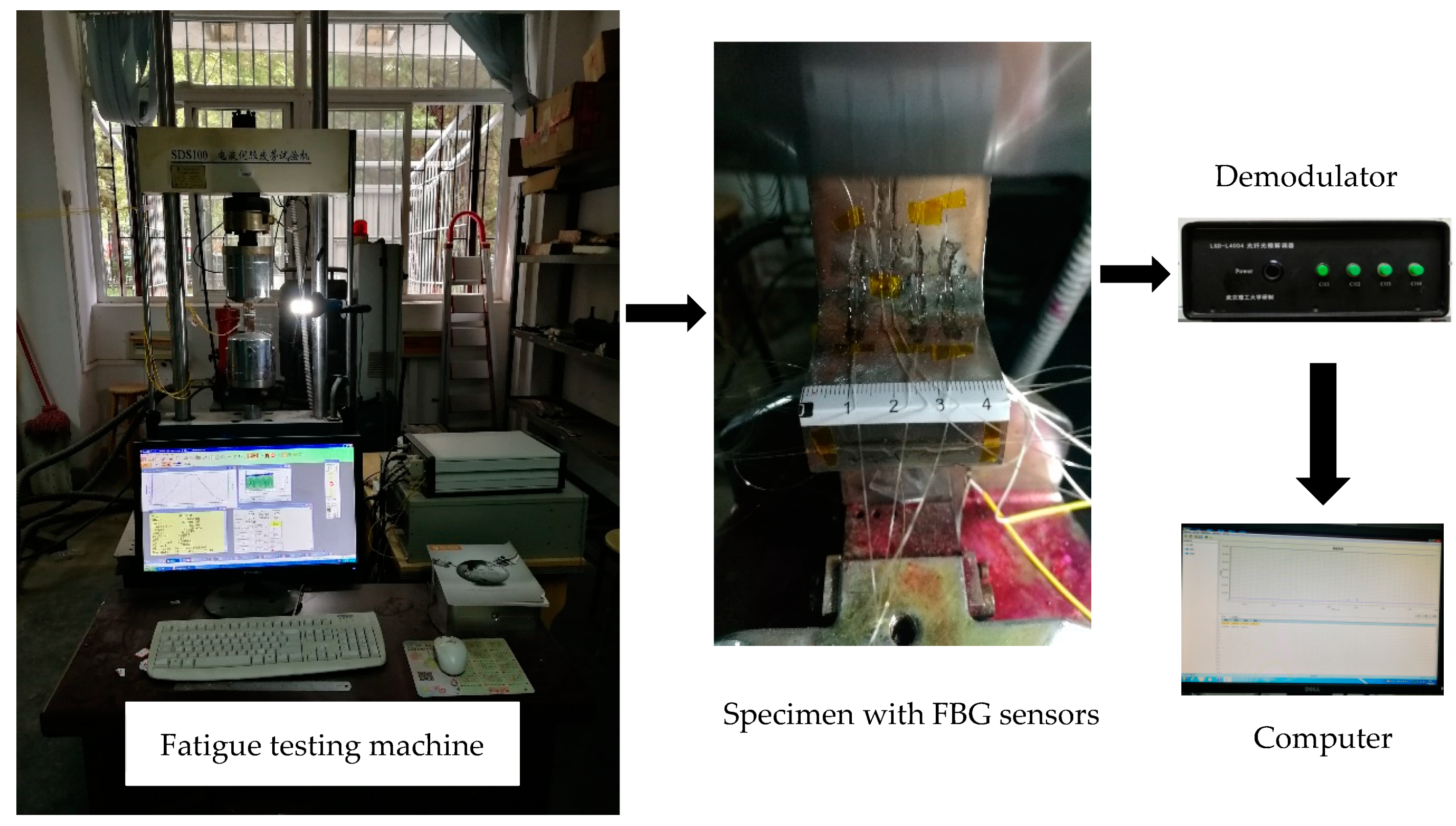
During the testing, the real-time FBG wavelengths of the five FBG sensors have been demodulated and recorded by a homemade FBG interrogator (with acquisition frequency of 100 Hz, accuracy of 5 pm, resolution of 1 pm), which can be shown in Figure 8. There was no pause in the whole testing process to ensure the continuity of the collected data. The final stop of the test was set to be the specimen deformation with limitation of ± 6 mm.
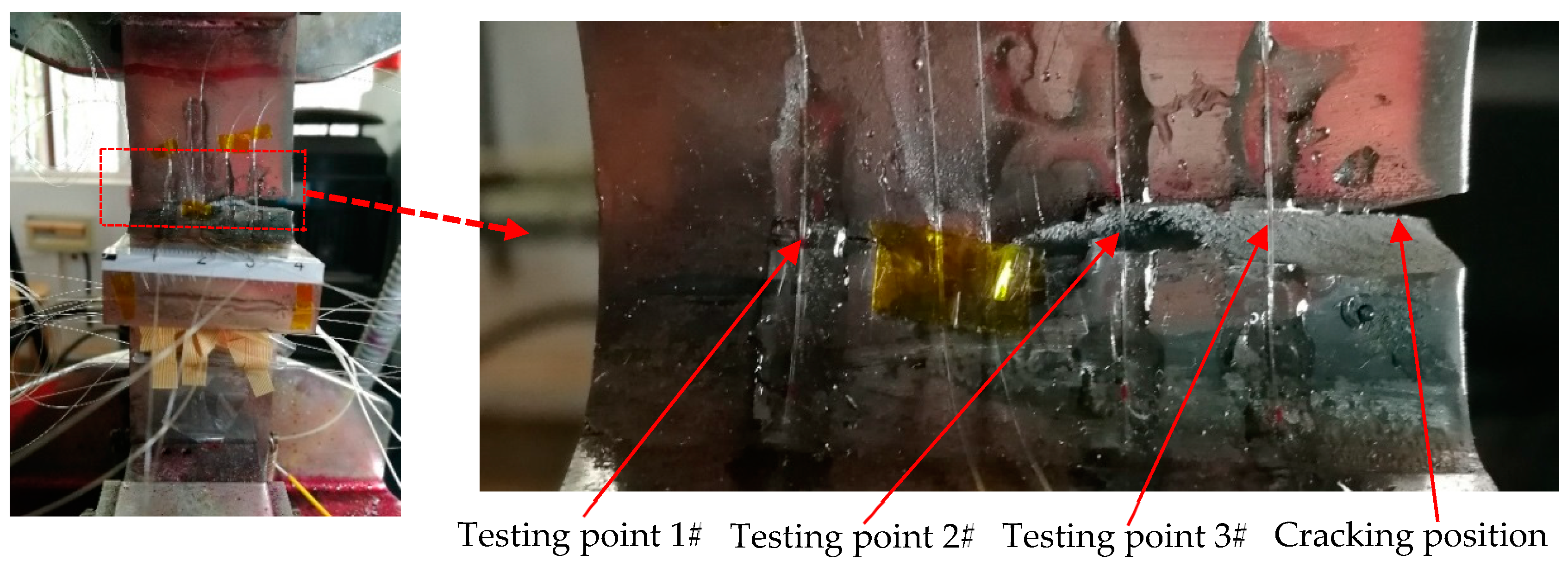
When the specimen experienced 567,000 load cycles, the equipment stopped working because the specimen deformation exceeded the preset protection value. At that moment, there was some obvious partial fracture on the weld of the specimen, as shown in Figure 9.

4. Results

4.1. Time History

The data directly measured by FBG is the changes in the grating Bragg wavelength at the testing point. The relationship between the testing point strain ε and the measured value can be expressed as Equation (11).
ε = ( λ c o λ s t a r t ) × 1000 / k ε
where λ c o is the real-time wavelength value collected by FBG, λ s t a r t is the initial wavelength value when the FBG is unloaded, k ε is the strain sensitivity coefficient of FBG. Table 4 shows that the Bragg wavelength used in this paper is between 1530 and 1555. Here, k ε is set to be 1.2 pm/με.
According to Equation (11), the testing signals at all the testing points were processed, and the strain time history of testing points were obtained, and the corresponding curves were drawn. Figure 10 shows the strain time history curve of the testing point 0#. According to Table 4, the testing point 0# is located on the surface of the specimens’ thin plate, which is far away from the weld toe. It is mainly used to verify nominal stress during the testing process. From Figure 10, the testing point 0# generally exhibits a constant amplitude strain of R = 0 and εmax is 986 με. Considering E = 2.06 × 10⁵ MPa given in Table 1, σmax = 203.1 MPa can be calculated, which is satisfying with the maximum nominal testing stress 200 MPa. So it indicates that the FBG has sufficient testing accuracy and reliability. At the end of the test, as the crack size approached gradually to the critical size, the strain near this testing point was rapidly increased. When the specimen broke instantaneously, the strain fell to zero quickly. The duration of the broken stage is extremely short, with only about 19.9 s, which corresponds to the instantaneous fracture of the specimen.
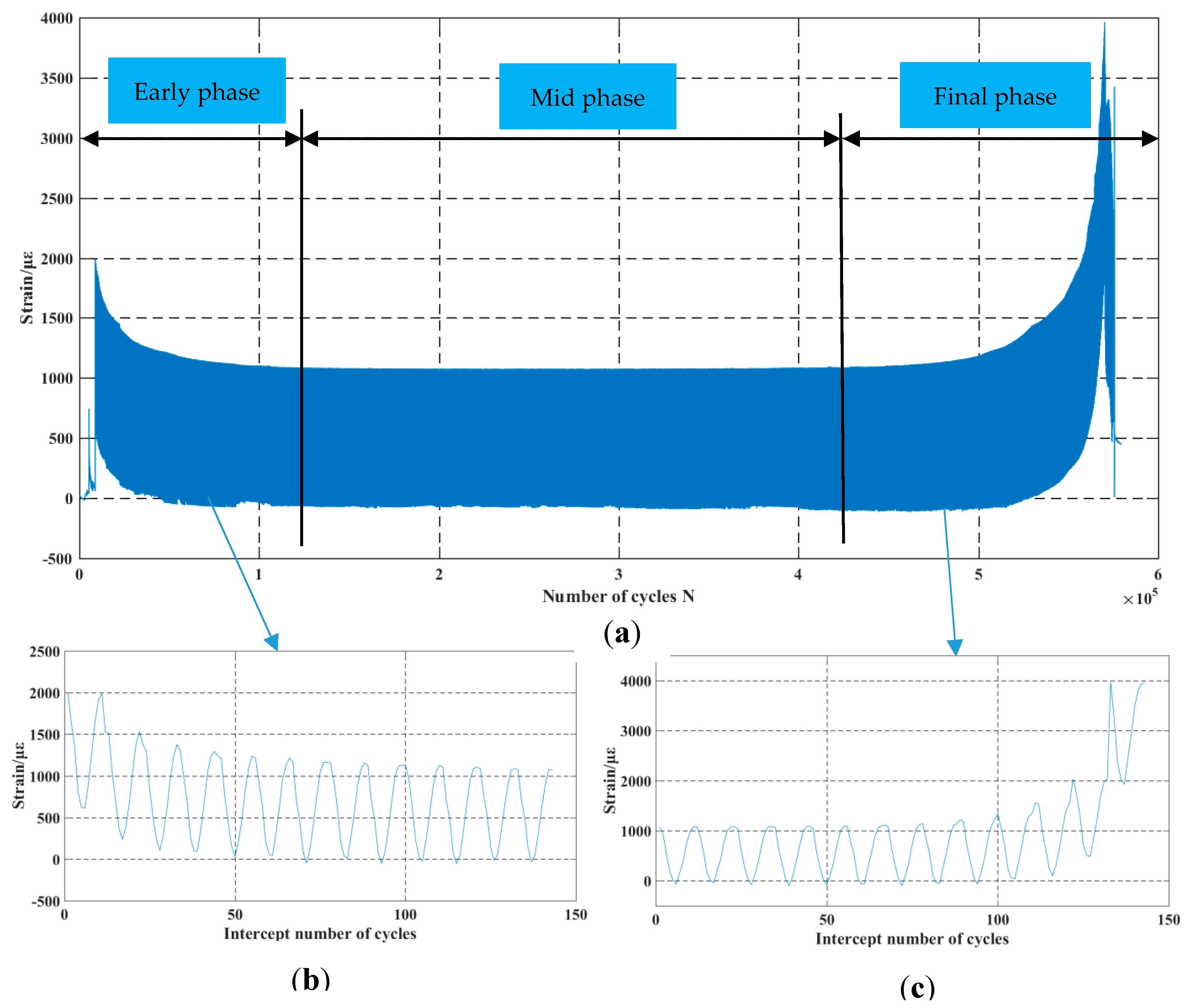
Figure 11 shows the strain time history curve of testing point 3#, where Figure 11a is the overall signal curve. It can be seen that the overall strain time history of this testing point can be divided into three phases: the “strain decline” phase (Early phase), the “strain stationary” phase (Mid phase), and the “strain rise and falls sharply” phase (Final phase), among which the “strain stationary” phase lasts a long time, accounting for about 52% of the total time. In the "strain stationary" phase, εmax = 1078 με, εmin = −81 με, Δε = 1159 με. εmax is slightly higher than the nominal testing strain, and SCFε = 1.09, SCFΔε = 1.18. It is worth noting that there is a small amount of compression strain in the stable phase.
Figure 11b shows the signal curve of the early phase. In order to make the strain trend more clearly, one strain cycle in Figure 11b is extracted from sequential 13 actual loading cycles. It can be seen that both the εmax and εmin in one cycle gradually decrease until they become stable in the “strain stationary” phase, indicating that the material near this testing point has obvious cyclic hardening characteristics, which leads to the weakening of SCF. In the first cycle in Figure 11b, εmax = 1990 με, εmin = 616 με, Δε = 1374 με. Then, SCFε = 2.02, SCFΔε = 1.39 can be calculated according to Equations (2) and (4). Compared with the SCFσ of the corresponding testing point in Table 3, SCFε is very close to SCFσ, which is mainly due to the small portion of plastic strain in total strain. Therefore, SCFε in the first cycle can be regarded as the SCFσ. From this aspect, the test results are consistent with the theoretical analysis.
Figure 11c shows the signal curve of the final phase, which is similarly dealt with as Figure 11b. In the last cycle, cracks are assumed to have occurred in the weld toe, which causes the carrying capacity of the material near the testing point to decrease and εmax and εmin to increase. In Figure 11c, the maximum strain value εmax is 3962 με, with which the specimen fracture unstably.
It is noteworthy that, the above characteristics are also shown in testing point 1# and 2#, only with different characteristic values, as shown in Table 5. According to Table 4, the three testing points are the characteristic points of SCF on the weld toe. Table 5 shows that all these three testing points have an obvious cyclic hardening effect in the early phase and plastic yielding phenomenon in the final phase. If SCF is calculated according to the maximum stain in the first cycle, SCF of the testing point 3# is the largest and is closest to the theoretical value, while SCF of the testing point 1# and 2# are both smaller than the theoretical value. It further demonstrates that the theoretical SCF formula cannot accurately characterize the actual stress and strain state at the weld toe.

4.2. Stress-Strain Response Curve

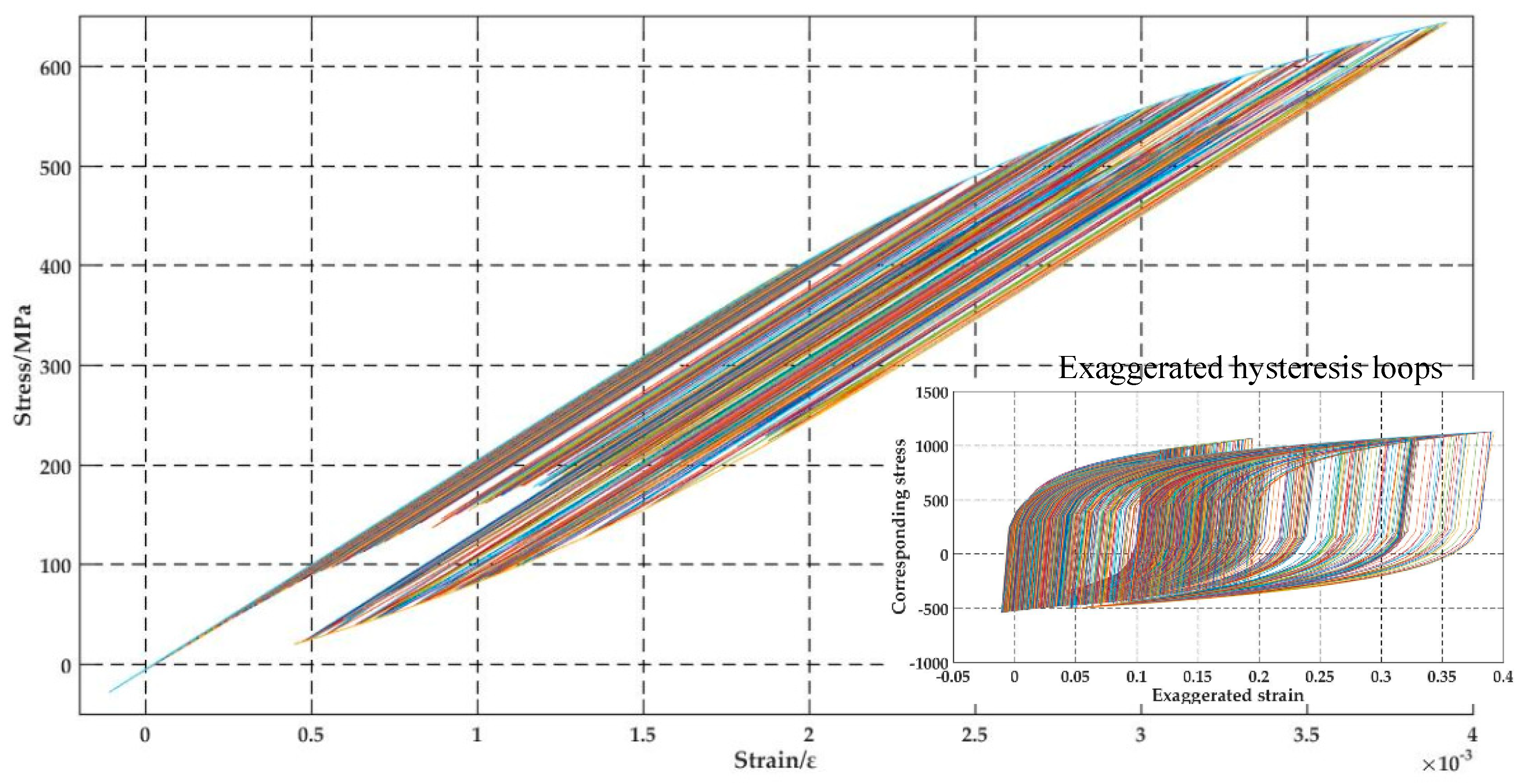
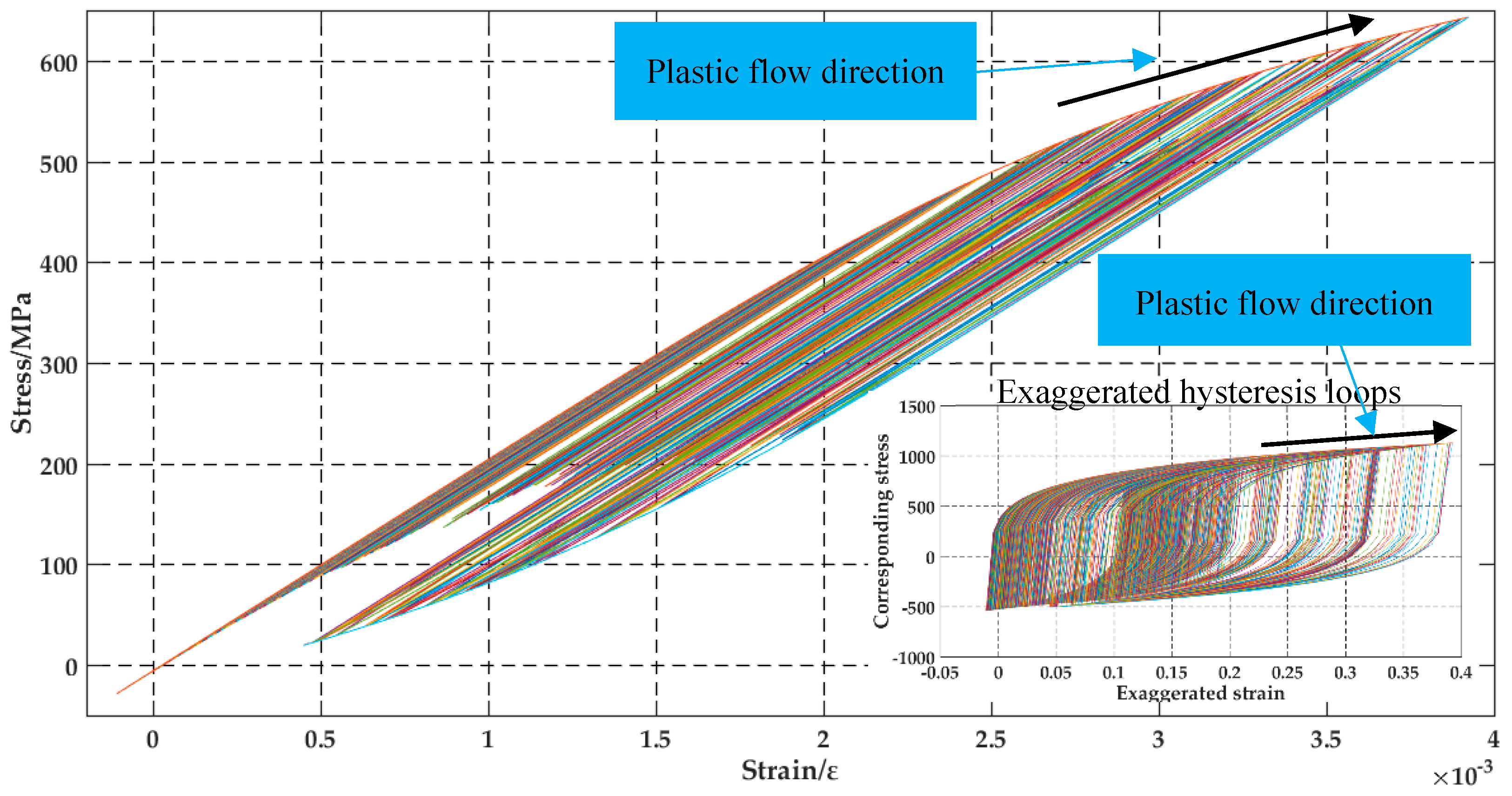
The peak-valley value was extracted from the strain time history collected from the test. According to the material parameters in Table 1, the stress-strain response of testing points can be calculated considering the cyclic behavior and memory effect of the material. Since the total loading cycles of the test were numerous, in order to improve the calculating efficiency and display the figures more clearly, only one peak-valley value was extracted from every 100 sequential cycles. The obtained stress-strain response curve for testing point 3# is shown in Figure 12, in which an obvious shift of stress-strain loops can be seen. If the strain values are amplified, exaggerated hysteresis loops can be generated, shown as the sub-figure in Figure 12. It needs to be mentioned that the stress and the strain in the sub-figure are not of real values, but can help to distinguish the different stages more clearly. Generally, a hysteresis loop is formed due to plastic dissipation when the cyclic stress and strain exceed the yield strength of the material. Although the testing stress is lower than the yield strength of the material in this test, SCF in the weld toe causes the actual stress and strain in the weld toe to exceed the yield strength and then results in hysteresis loop phenomenon.
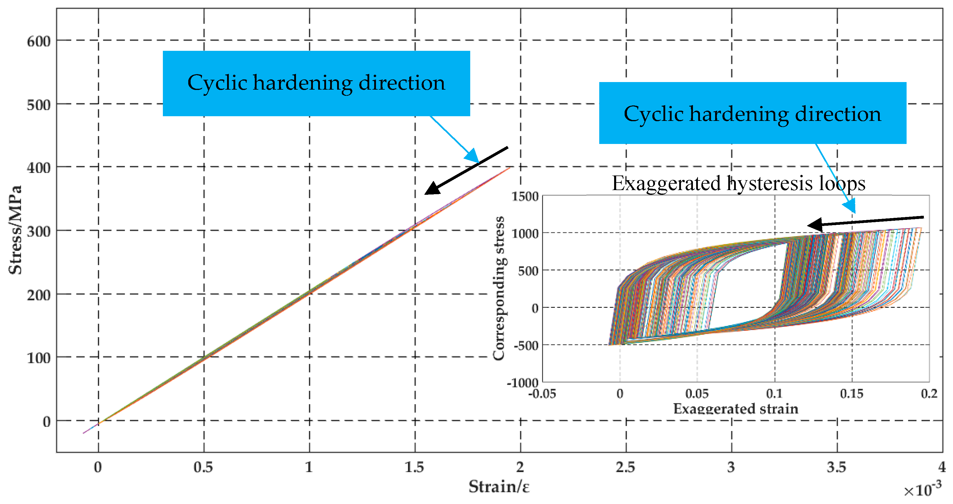
According to the different phases of the testing point 3#, the corresponding stress-strain response curves were drawn, as shown in Figure 13, Figure 14 and Figure 15. Figure 13 illustrates the “strain decline” phase corresponds to 1-80472 loading cycles. It can be seen that as the number of load cycles increases, the stress-strain curve gradually shifts to the lower-left as a straight-line shape which exhibits cyclic hardening behavior. In the sub-figure, it can be seen that the shape of the hysteresis loop is almost unchanged in the first several cycles and then becomes stable in the last several cycles. During the cyclic hardening process, Δε of different cycles almost equals to 1970 με and Δσ almost equals to 407 MPa, which reflects the test was conducted under the constant amplitude stress and strain state. However, the maximum stress and strain are decreased with the maximum εmax of 1951 με and the maximum σmax of 398 MPa. By calculating, S C F σ = 1.99 , S C F ε = 1.98 , S C F Δ σ = 2.03 , S C F Δ ε = 2.00 , which exhibits strong stress-strain concentration effects. Due to the cyclic hardening behavior, SCF will decrease as the number of cycles increases. Then the strain stress response curve becomes approximate line shape.
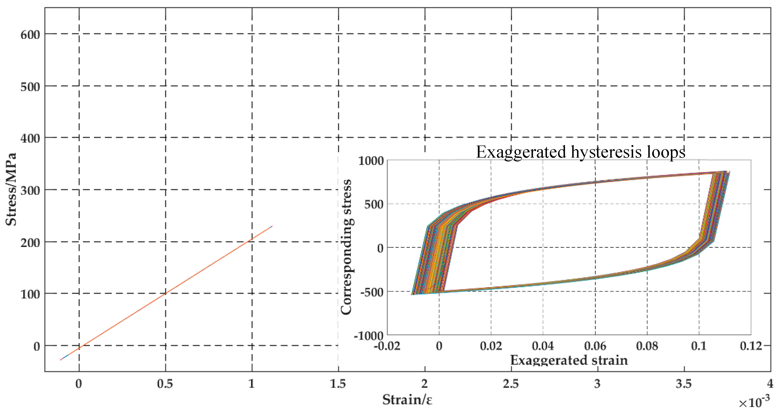
Figure 14 shows the “strain stationary” phase corresponding to 80473-458382 loading cycles, which lasts a long time. It can be seen that the stress is almost linear to the strain and lies in the elastic region, indicating that the stress and strain in this phase are lower than the yield strength of the weld material. There is nearly no hysteresis loop in this phase, but the stress-strain curves also shift gradually from top-right to bottom-left. It should be emphasized again here that the loops in the sub-figure are only for showing and are not with the real values of stresses and strains. When the stress-strain cycles are stable, Δε = 1148 με, Δσ = 240 MPa, εmax = 1075 με, σmax = 220 MPa. By calculating,   S C F σ = 1.10 , S C F ε = 1.11 , S C F Δ σ = 1.20 , S C F Δ ε = 1.18 , which exhibits weakened SCF compared with that in the “strain decline” phase. Therefore, during the “strain stationary” phase, the weld toe is in the stress and strain state similar to the testing nominal state.
Figure 15 illustrates the “strain rise and fall sharply” phase corresponding to 458383-566742 loading cycles. It can be seen that the material at this testing point is in a distinct plastic state. The hysteresis loops shift rapidly from bottom-left to top-right. σmax, εmax, Δσ and Δε all increase rapidly until the specimen fracture unstably. At that moment, the fatigue machine stopped, and the stress and strain quickly decrease to approximate zero.
Similar rules can be drawn by performing the same processing for testing points 1# and 2#. Take the “strain stationary” phase as the datum mark, whose two ends are taken as the boundary of different stages. Key parameters of the three stages are listed in Table 6.
It can be seen from Table 6 that the key parameters of the three stages of testing points 1#, 2# and 3# exhibit a similar trend. The “strain decline” phase of testing point 3# has the longest duration, meanwhile, the “strain rise and fall sharply” phase begins first. The “strain decline” phase of testing point 1# has the shortest duration. Meanwhile, the “strain rise and fall sharply” phase begins latest. Comparing the stress and strain parameters, it can be found that most statistic values of testing point 3# are higher than those of testing point 1# and 2#, which indicates that the actual stress-strain state of testing point 3# is more severe than those of the other two testing points.

5. Discussion

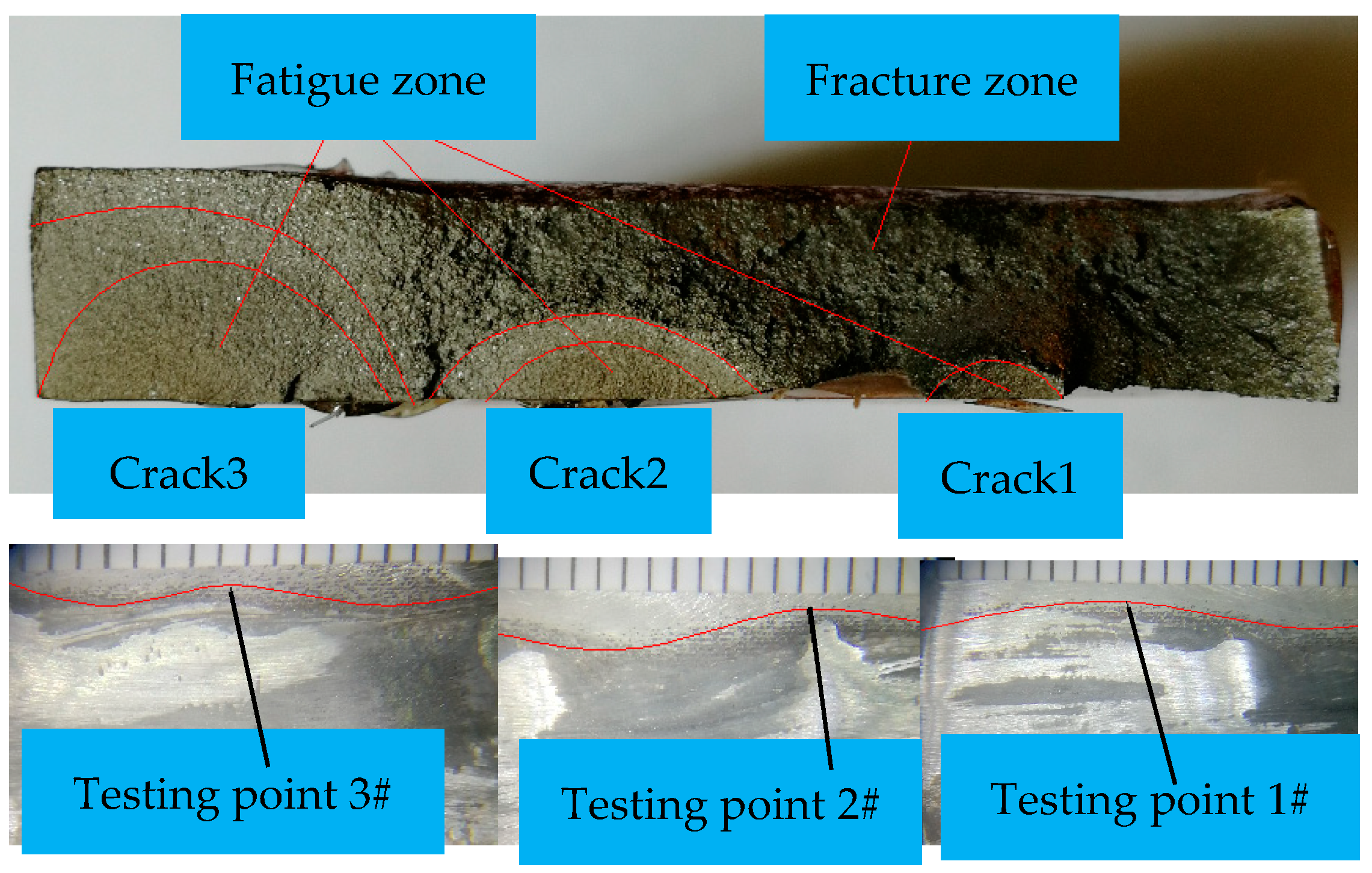
The final fatigue fracture surface of the specimen is shown in Figure 16, where the fatigue zone and the instantaneous fracture zone can be clearly observed. Three obvious cracks are visible in the fatigue zone, which are labeled as crack 1, crack 2 and crack 3, respectively. All the three cracks have crack fronts with semi-elliptical shape, whose centers correspond to the crack initiating positions. Relating these three positions with the weld toe geometry captured before testing, it can be seen that three cracks were all initiated in the positions with a larger SCF. In another word, three cracks all initiated near the testing points, which indicates that the cracks initiation depends greatly on the local stress and strain state at the weld toe. Considering the weld toe geometry characteristics discussed in the study above, it can be drawn that geometric points such as convex vertices of the arc segment along the weld toe curve are prone to fatigue damage and should be paid more attention to in engineering application.
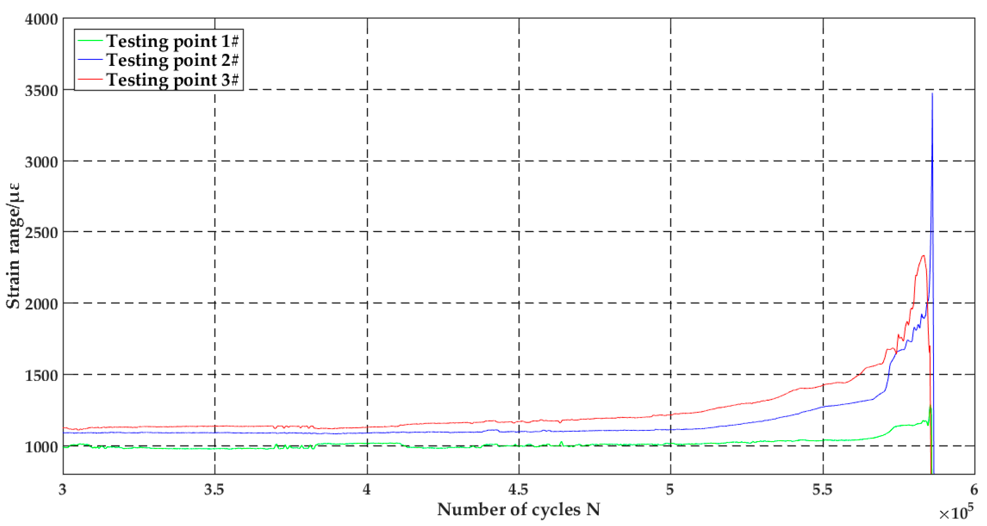
In addition, Figure 16 shows that the size and brightness of the three cracks are significantly distinct, reflecting the degrees of oxidation of the cracked surfaces are different from each other, which can indirectly indicate that the initiation time of the three cracks is unsynchronized. Specifically, crack3 is firstly initiated at testing point 3#, and then crack2 at testing point 2# and at last, crack 1 at testing point 1#. The end parts (300,000 cycles-end) of the strain time history of the three testing points were extracted, and the strain range curves were drawn in Figure 17. It shows a trend of stable-rise and rapid-drop. Among the three curves, testing point 3# with the largest SCF first exhibits a mutation, according to which mechanical explanation for the unsynchronized initiation of weld toe cracks can be proposed. When the specimen is subjected to cyclic loads, the site with the largest S C F on the weld toe (for example, testing point 3#) firstly satisfies the crack initiation condition, the first crack initiates and propagates at both the longitudinal direction and the thickness direction simultaneously. As the crack surface becomes larger, the actual load-carrying sectional area of the specimen gradually decreases. Consequently, stresses and strains at another site with the second largest S C F (for example, testing point 2#) increases continuously till it satisfies the crack initiation condition, too. Then, a new crack initiates at this site. This process repeats again and again until the specimen cannot resist the load anymore, resulting in final fracture. Therefore, in some way, the irregular shape of the weld toe directly affects the stress and strain state at the weld toe. If weld defects are not considered, it will further determine multiple cracks phenomenon at the weld toe and the unsynchronized characteristics of these cracks.

6. Conclusions

Aiming at the difficulties of local strain measuring for welded joints, an FBG sensor based method was proposed, and the corresponding fatigue test was conducted. Strains at some characteristic points along the weld toe under the cyclic tensile load were recorded, and the strain time histories were drawn and analyzed. The following conclusions can be drawn:
(1)
FBG has small section size, good flexural resistance and can be arranged across the characteristic points at the weld toe. Compared with other strain sensors, it can obtain the complete cyclic strain time history of the weld toe more accurately and reliably, which has great advantages for the experimental investigation and SHM for welded structures.
(2)
Under the cyclic loading, the strain time history of the weld toe can be divided into three distinct phases, in which cyclic hardening effect in the early phase and plastic flow behavior in the final phase are obvious and influence greatly on the mechanical behaviors for welded joints.
(3)
Both experiment investigation and theoretical analysis show that the local stress and strain state at the weld toe is the vital factor which affects the fatigue performance of welded joints without considering the weld defects. Geometric points such as convex vertexes of the arc segment are potential positions for fatigue damage, which should be paid more attention to.
(4)
Generally, the weld toe curves of welded joints are irregular, which result in variable SCF along the weld toe. Under cyclic loads, different geometry characteristic points along the weld toe satisfy the crack initiation condition one after another, resulting in multiple cracks of the weld toe and their unsynchronized initiation moment.

Author Contributions

Conceptualization, G.W., S.L., Y.G., and Z.D; Methodology, G.W. and Y.G.; Software, S.L.; Data Curation, G.W. and S.L.; Validation, G.W., S.L., and Y.G.; Formal Analysis, G.W. and S.L.; Investigation, S.L.; Resources, G.W., Y.G., and Z.D; Visualization, G.W. and S.L.; Writing—original draft, S.L.; Writing—review & editing, G.W. and Y.G.; Supervision, G.W., Y.G., and Z.D.

Funding

This work is supported by National Natural Science Foundation of China (No. 51575408).

Acknowledgments

The authors would like to thank the reviewers’ efforts in reading the manuscript.

Conflicts of Interest

The authors declare no conflict of interest.

References

  1. Radaj, D. Review of fatigue strength assessment of nonwelded and welded structures based on local parameters. Int. J. Fatigue 1996, 18, 153–170. [Google Scholar] [CrossRef]
  2. Radaj, D.; Sonsino, C.M.; Fricke, W. Recent developments in local concepts of fatigue assessment of welded joints. Int. J. Fatigue 2009, 31, 2–11. [Google Scholar] [CrossRef]
  3. Jonsson, M.B.; Samuelsson, J.; Marquis, G.B. Development of weld quality criteria based on fatigue performance. Weld. World 2011, 55, 79–88. [Google Scholar] [CrossRef]
  4. Schijve, J. Fatigue predictions of welded joints and the effective notch stress concept. Int. J. Fatigue 2012, 45, 31–38. [Google Scholar] [CrossRef]
  5. Sonsino, C.M.; Fricke, W.; Bruyne, F.D.; Hoppe, A.; Ahmadi, A.; Zhang, G. Notch stress concepts for the fatigue assessment of welded joints–Background and applications. Int. J. Fatigue 2012, 34, 2–16. [Google Scholar] [CrossRef]
  6. Gurney, T.R. Fatigue of Welded Struct; Cambridge University Press: Cambridge, UK, 1978. [Google Scholar]
  7. Radaj, D.; Sonsino, C.M. Fatigue Assessment of Welded Joints by Local Approaches; Woodhead Publishing: Cambridge, UK, 1998. [Google Scholar]
  8. Lassen, T.; Recho, N. FLAWS–Fatigue Life Analyses of Welded Structures; ISTE: Washington, DC, USA, 2006. [Google Scholar]
  9. Ye, N.; Moan, T. Improving fatigue life for aluminimum cruciform joints by weld toe grinding. Fatigue Fract. Eng. Mater. Struct. 2008, 31, 152–163. [Google Scholar] [CrossRef]
  10. Nykanen, T.; Marquis, G.; Bjork, T. A simplified fatigue assessment method for high quality welded cruciform joints. Int. J. Fatigue 2009, 31, 79–87. [Google Scholar] [CrossRef]
  11. He, B.L.; Yu, Y.X.; Zhang, X.D.; Xia, S.S. Calculation about Stress Concentration Coefficient of Welded Cruciform Joints of Magnesium Alloy Based on FEM. Adv. Mater. Res. 2014, 989–994, 931–934. [Google Scholar] [CrossRef]
  12. Brennan, F.P.; Peleties, P.; Hellier, A.K. Predicting weld toe stress concentration factors for T and skewed T-joint plate connections. Int. J. Fatigue 2000, 22, 573–584. [Google Scholar] [CrossRef]
  13. Ramalho, A.L.; Ferreira, J.A.; Branco, C.A. Fatigue behaviour of T welded joints rehabilitated by tungsten inert gas and plasma dressing. Mater. Des. 2011, 32, 4705–4713. [Google Scholar] [CrossRef]
  14. Radaj, D. Theory of forces and stresses in spot welded overlap joints. Arch. Appl. Mech. 1996, 67, 22–34. [Google Scholar] [CrossRef]
  15. Tsuyoshi, S.; Naoki, Y.; Yoshikiyo, T.; Jiro, H.; Kazuhiro, O. Effect of weld toe geometry on fatigue life of lap fillet jointed ultra-high strength steel joints. Int. J. Fatigue 2018, 116, 409–420. [Google Scholar]
  16. Deng, D.; Murakawa, H.; Liang, W. Numerical and experimental investigations on welding residual stress in multi-pass butt-welded austenitic stainless steel pipe. Comput. Mater. Sci. 2008, 42, 234–244. [Google Scholar] [CrossRef]
  17. Steimbreger, C.; Chapetti, M.D. Fatigue strength assessment of butt-welded joints with undercuts. Int. J. Fatigue 2017, 105, 296–304. [Google Scholar] [CrossRef]
  18. Pandey, C.; Giri, A.; Mahapatra, M.M. On the prediction of effect of direction of welding on bead geometry and residual deformation of double-sided fillet joints. Int. J. Steel Struct. 2016, 16, 333–345. [Google Scholar] [CrossRef]
  19. Kainuma, S.; Mori, T. A fatigue strength evaluation method for load-carrying fillet jointed cruciform joints. Int. J. Fatigue 2006, 28, 864–872. [Google Scholar] [CrossRef]
  20. Lee, C.H.; Chang, K.H.; Jang, G.C.; Lee, C.Y. Effect of weld geometry on the fatigue life of non-load-carrying fillet jointed cruciform joints. Eng. Fail. Anal. 2009, 16, 849–855. [Google Scholar] [CrossRef]
  21. Kiyak, Y.; Madia, M.; Zerbst, U. Extended parametric equations for weld toe stress concentration factors and through-thickness stress distributions in butt-welded plates subject to tensile and bending loading. Weld. World 2016, 60, 1–13. [Google Scholar] [CrossRef]
  22. Djoković, J.M.; Nikolić, R.R. Influence of the Joint Geometry on the Stress Intensity Factor of the Fillet jointed Cruciform Joint Subjected to Tension and Bending. Mater. Today Proc. 2016, 3, 959–964. [Google Scholar] [CrossRef]
  23. Meneghetti, G.; Campagnolo, A.; Berto, F. Fatigue strength assessment of partial and full-penetration steel and aluminium butt-welded joints according to the peak stress method. Fatigue Fract. Eng. Mater. Struct. 2015, 38, 1419–1431. [Google Scholar] [CrossRef]
  24. Hou, C.Y. Fatigue analysis of welded joints with the aid of real three-dimensional weld toe geometry. Int. J. Fatigue 2007, 29, 772–785. [Google Scholar] [CrossRef]
  25. Kang, J.; Ososkov, Y.; Embury, J.D.; Wilkinson, D.S. Digital image correlation studies for microscopic strain distribution and damage in dual phase steels. Scr. Mater. 2007, 56, 999–1002. [Google Scholar] [CrossRef]
  26. Agarwal, G.; Gao, H.; Amirthalingam, M.; Hermans, M.J.M. In-situ strain investigation during laser welding using digital image correlation and finite element based numerical simulation. Sci. Technol. Weld. Join. 2017, 23, 1–6. [Google Scholar] [CrossRef]
  27. Otegui, J.L.; Mohaupt, U.H.; Burns, D.J. A strain gauge technique for monitoring small fatigue cracks in welds. Eng. Fract. Mech. 1991, 40, 549–569. [Google Scholar] [CrossRef]
  28. Lukashevich, A.O.; Leonets’, V.A.; Chaus, L.M. Strain-Gauge Method of Detecting Subcritical Fatigue Cracks in Low-Carbon Steel Welds. Strength Mater. 2015, 47, 467–473. [Google Scholar] [CrossRef]
  29. Takeuchi, K. Locations of strain gauges for fatigue analysis of welded joints (1). Weld. Int. 2012, 26, 559–566. [Google Scholar] [CrossRef]
  30. Takeuchi, K. Locations of strain gauges for fatigue analysis of welded joints (2). Weld. Int. 2012, 26, 655–664. [Google Scholar] [CrossRef]
  31. Mirapeix, J.; Cobo, A.; Conde, O.M. Real-time arc welding defect detection technique by means of plasma spectrum optical analysis. NDT&E Int. 2006, 39, 356–360. [Google Scholar]
  32. Zhang, X.J.; Chen, J.; Álvaro, G.V.; Liu, F. Twist sensor based on surface plasmon resonance excitation using two spectral combs in one tilted fiber Bragg grating: publisher’s note. J. Opt. Soc. Am. B 2019, 36, 1176–1182. [Google Scholar] [CrossRef]
  33. Ye, X.W.; Su, Y.H.; Xi, P.S. Statistical Analysis of Stress Signals from Bridge Monitoring by FBG System. Sensors 2018, 18, 491. [Google Scholar] [Green Version]
  34. Hu, D.T.; Guo, Y.X.; Chen, X.F.; Zhang, C.R. Cable Force Health Monitoring of Tongwamen Bridge Based on Fiber Bragg Grating. Appl. Sci. 2017, 7, 384. [Google Scholar] [CrossRef]
  35. Güemes, A.; Fernández-López, A.; Díaz-Maroto, P. Structural Health Monitoring in Composite Structures by Fiber-Optic Sensors. Sensors 2018, 18, 1094. [Google Scholar] [CrossRef] [PubMed]
  36. Mitchell, M.R.; Rockwell Science Center. Fundamentals of Modern Fatigue Analysis for Design. Fatigue Fract. ASM Handb. Comm. 1996, 19, 227–249. [Google Scholar]
  37. Xiong, L.; Jiang, G.; Guo, Y. A Three-dimensional Fiber Bragg Grating Force Sensor for Robot. IEEE Sens. J. 2018, 9, 3632–3639. [Google Scholar] [CrossRef]
  38. Wu, L.; Maheshwari, M.; Yang, Y.; Xiao, W. Selection and Characterization of Packaged FBG Sensors for Offshore Applications. Sensors 2018, 18, 3963. [Google Scholar] [CrossRef] [PubMed]
  39. Luo, Y.R.; Wang, Q.Y.; Liu, Y.J. Low cycle fatigue properties of steel structure materials Q235 and Q345. J. Sichuan Univ. 2012, 44, 169–175. [Google Scholar]
  40. Qin, D.; Ping, Y.; Geng, X.; Deng, J.L. Mechanisms and modeling of low cycle fatigue crack propagation in a pressure vessel steel Q345. Int. J. Fatigue 2016, 89, 2–10. [Google Scholar]
  41. Zerbst, U.; Ainsworth, R.A.; Beier, H.T. Review on fracture and crack propagation in weldments–A fracture mechanics perspective. Eng. Fract. Mech. 2014, 132, 200–276. [Google Scholar] [CrossRef]
  42. Jinachandran, S.; Li, H.; Xi, J. Fabrication and Characterization of a Magnetized Metal-Encapsulated FBG Sensor for Structural Health Monitoring. IEEE Sens. J. 2018, 18, 8739–8746. [Google Scholar] [CrossRef] [Green Version]
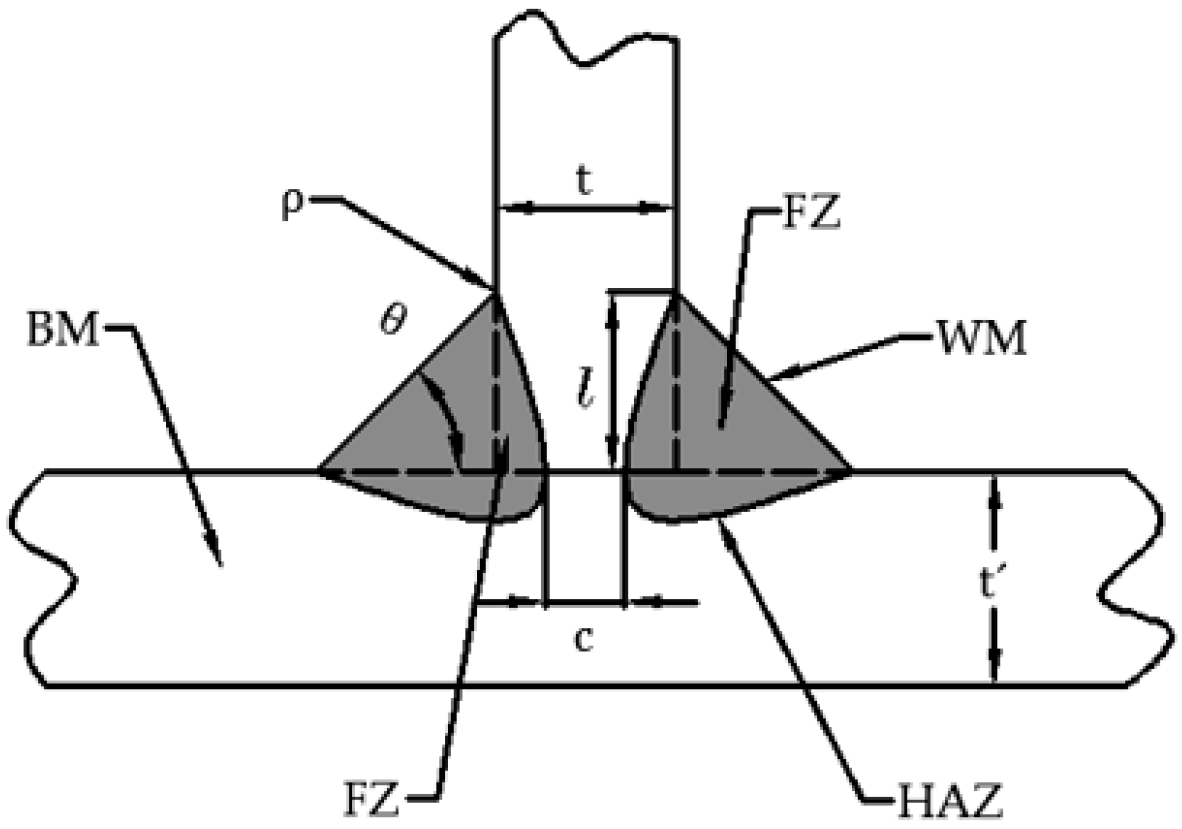
Figure 1. Schematic diagram of the fillet joint.
Applsci 09 02939 g001
Figure 2. Schematic diagram of the butt joint.
Applsci 09 02939 g002
Figure 3. Local detail of the weld toe of the weld section.
Applsci 09 02939 g003
Figure 4. Schematic diagram of working principle of Fiber Bragg Grating (FBG).
Applsci 09 02939 g004
Figure 5. Cruciform welded joint: (a) Geometry of the specimen (mm); (b) 3D model of the specimen.
Applsci 09 02939 g005
Figure 6. Characteristic points on the weld toe curve.
Applsci 09 02939 g006
Figure 7. Schematic diagram of FBG arrangement.
Applsci 09 02939 g007
Figure 8. Cyclic strain testing system.
Applsci 09 02939 g008
Figure 9. Testing points arrangement and specimen fracture.
Applsci 09 02939 g009
Figure 10. Strain time history curve (testing point 0#).
Applsci 09 02939 g010
Figure 11. Strain time history curve (testing point 3#): (a) Overall process; (b) Early phase (“strain decline” Phase); (c) Final phase (“strain rise” phase).
Applsci 09 02939 g011
Figure 12. Strain stress response curve (testing point 3#).
Applsci 09 02939 g012
Figure 13. Strain stress response curve (“strain decline” phase for testing point 3#).
Applsci 09 02939 g013
Figure 14. Strain stress response curve (“strain stationary” phase for testing point 3#).
Applsci 09 02939 g014
Figure 15. Strain stress response curve (“strain rise and fall sharply” phase for testing point 3#).
Applsci 09 02939 g015
Figure 16. Comparison of cracks position and testing points.
Applsci 09 02939 g016
Figure 17. Strain range curve of the final phase.
Applsci 09 02939 g017
Table 1. Basic mechanical parameters of the specimen.
σ s   ( MPa ) σ b   ( MPa ) δ (%)E (MPa) μ K (MPa) n
38554025.52.06 × 1050.312810.2069
Table 2. Chemical compositions of the specimens (%).
CSiMnPSAl
0.160.351.340.160.060.0004
Table 3. Parameters and SCF of characteristic weld sections.
No.123456789101112
L (mm)3.25.89.114.617.426.928.730.534.836.940.342.2
T (mm)7.988.288.328.168.008.427.928.268.247.868.128.08
θ (°)42.8145.6143.2342.4342.5743.9242.4242.6345.3643.0442.3946.47
l (mm)7.747.437.827.267.517.467.037.538.328.047.137.48
ρ (mm)1.081.141.041.121.111.051.131.120.911.031.101.12
Kt1.931.951.971.921.921.981.901.932.061.951.93 1.95
Remarks 1# 2# 3#
Table 4. Description of testing points.
No. of Testing PointsGrating Bragg Wavelength (nm)Position of Testing PointsPurpose of Testing Points
0#1547Surface of thin plateNominal stress verification
1#1541L-9.1 mmLocal strain measuring
2#1532L-26.9 mmLocal strain measuring
3#1550L-34.8 mmLocal strain measuring
T1555Surface of thick plateTemperature compensation
Table 5. Strain testing results (με).
Number of Testing Points“Strain Decline” Phase“Strain Stationary” Phase“Strain Rise and Fall Sharply” PhaseSCF
εmaxεminΔεεmaxεminΔεεmaxεminΔε
0#953239309865981234613619851
1#13512191132954−5510094584330012841.42
2#168845012381035−7211076416433820781.77
3#199061613741078−8111593962192520372.09
Table 6. Key parameters of the stress-strain curves.
PhaseNo. of Testing PointBegin CycleEnd CycleStrain (με)Stress (MPa)
εmaxεminΔεmaxΔεminσmaxσminΔσmaxΔσmin
Strain decline1#157,1551354423135698128378286202
2#167,03616874531696108134687353221
3#180,472195156919701110398108407232
Strain stationary 1#57,156492,616953−1510029559198−6210200
2#67,037477,4991035−3310991053210−14232223
3#80,473458,3821075−8111481094220−23240230
Strain rise and fall sharply1#492,617566,74245383212462506924147110
2#477,500566,74263684315646607713818000
3#458,383566,74239241923403406392346700