Article

Synthesis and Diagnostics of Nanostructured Micaless Microcomposite as a Prospective Insulation Material for Rotating Machines

1
Department of Technologies and Measurement, Faculty of Electrical Engineering, University of West Bohemia, Univerzitní 8, 306 14 Pilsen, Czech Republic
2
New Technologies-Research Centre, University of West Bohemia, Univerzitní 8, 306 14 Pilsen, Czech Republic
*
Author to whom correspondence should be addressed.
Appl. Sci. 2019, 9(14), 2926; https://doi.org/10.3390/app9142926
Submission received: 10 July 2019 / Accepted: 19 July 2019 / Published: 22 July 2019
(This article belongs to the Section Nanotechnology and Applied Nanosciences)

Abstract

:
This paper deals with the topic of composite insulation materials for rotating machines and it is primarily pointed to the synthesis of new three-component insulation system. In connection with this research, the basic components of the insulation system are selected and described by different diagnostic methods. The proposed insulation material is composed of epoxy resin based on bisphenol-A diglycidyl ether, magnesium oxide nanofiller (1 wt %) with its own surface treatment technology using epoxysilane coupling agent ( γ -glycidoxypropyltrimethoxysilane) and polyethylene naphthalate as a reinforcing component. Following the defined topic of the paper, the proposed three-component insulation system is confronted with commonly used insulating systems (PET reinforced and Glass reinforced mica composites) in order to verify the basic dielectric properties (dielectric strength, volume resistivity, dissipation factor) and other parameters determined from phenomenological voltage and current signals, respectively.

1. Introduction

Dielectric materials of different forms and states are inseparable parts of high voltage applications. From the point of reliability, it is the weakest part of the reliability chain of the whole device [1]. For this reason, it is necessary to take an effort to the improvement of material parameters (electrical, mechanical or physical-chemical). It leads to the reduction of the probability of failure of the entire device [2]. Current trends in the field of design and diagnostics allow the usage and study of the materials containing components up to nanometric dimensions [3]. One way to achieve the desired improvement is to use composite materials [4] where the synergy effect of individual components is utilized. In the field of insulating systems for rotating machines, there are, in particular, three component composite materials, which are composed of a matrix, filler and reinforcement [5].
This area of composite insulation systems has undergone considerable development over the past 70 years. In the case of insulation systems for rotating machines, natural fibers from materials such as silk, cellulose, and linen were initially used. Natural varnishes from trees, plants and insects, or petroleum derivatives [6] were used as an impregnants.
Progress in the technology of composite insulating materials of rotating machines is dated to the time of use of mica leaves in unaltered form with cellulose reinforcement binded together with shellac or asphalt matrix [7]. This type of insulation is also known as a “soft” insulating system. The undisputed advantage of soft systems was their elasticity and the ability to fill the machine slot, completely without the spaces [8]. One of the main reasons for their replacements were limits in terms of the operating thermal class and voltage level or partial discharges developed in delamination due to the shrink.
Another milestone in this area was the incorporation of mica paper as a part of the insulation system in the middle of the 20th century [9]. At that time, also a development, research and application grew in the field of impregnants. Previously used bituminous varnishes being slowly replaced by synthetic resins. The most common representatives for electrotechnical applications are polyester [10], epoxy [11] and in special cases silicone [12] resins. Also natural fibers have been replaced over the time. Glass fibers, polyethylene terephthalate or polyethylene naphthalate films [13] are used today as a reinforcement. These so-called “hard” insulation systems can be operated at higher temperatures and voltage levels. Their disadvantage may be the fact that they do not sufficiently fill the slot of the machine, which in some cases may lead to the formation of slot partial discharges. The illustration of the stator winding with composite insulation is shown in Figure 1.
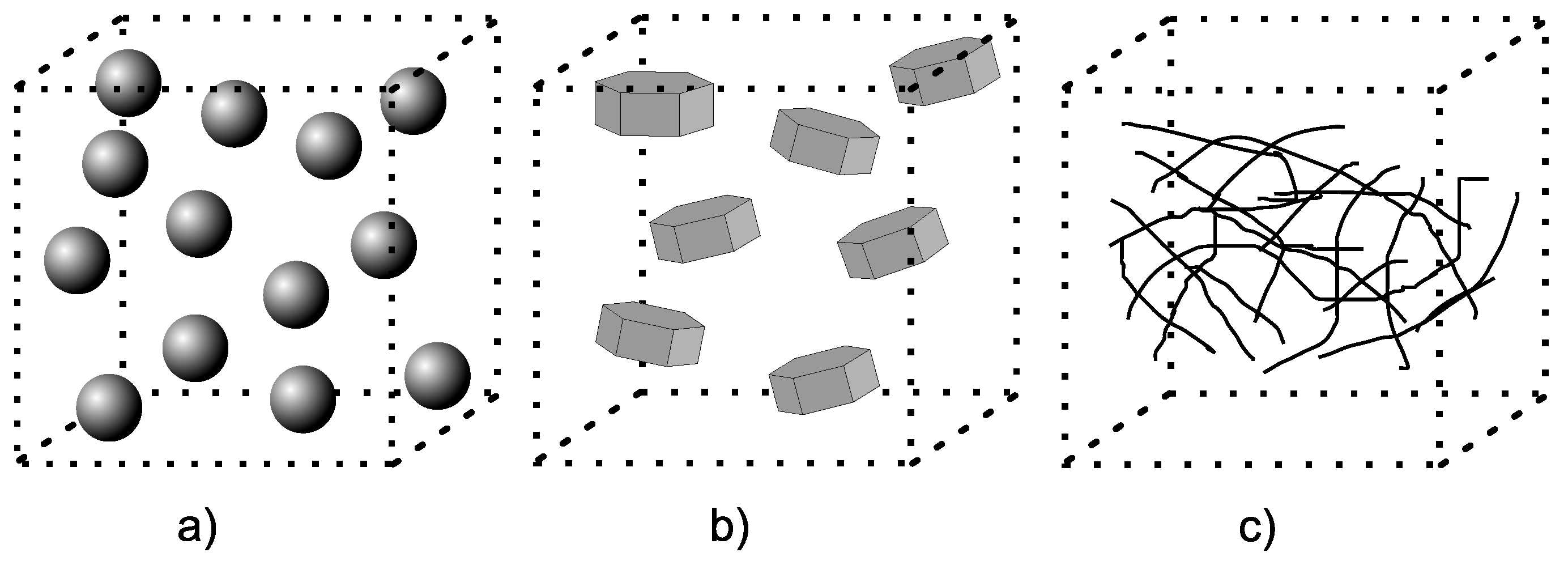
Another significant contribution from the historical perspective on the development of composite dielectrics and their electrical properties can be attributed to Johnston and Markovitz [14]. They used a nanometric fillers in corona resistant insulation at the beginning of the 1990s. As a next, Lewis defines the uniqueness of nanodielectrics in his article in 1994 [15]. Then, the nanodielectric systems become an object of interest of scientists and professionals from all over the world, who are discussing other options for modifications and potential applications [16]. The most frequent studied fillers (Figure 2) are simple oxides (SiO2 [17], Al2O3 [18], ZnO [19], TiO2 [20], MgO [21]), layered [22] or tubular [23] silicates, eventually also nonwoven nanoscale structures [24,25,26].
With the advent of last mentioned technologies, it is possible to characterize the composites as macro-, micro- and nano-. Globally, the macrostructural insulation system—macrocomposite—can be defined as a system containing in its structure components with dimensions larger than 100 microns in the transverse direction [27]. Analogously, the term micro- or nanocomposite, can be also defined. Because of the dimensions of the used components, these terms refer to commonly used three-component insulating systems for electrical rotating machines. The homogeneity level of the internal structure may be defined according to Figure 3. By replacing one macro- or microscopic interface (e.g., by dispersed nanoparticles), the formation of the so-called nanostructured microcomposite [16] can be achieved by the combination of the components of both characteristic dimensions (nano-, micro-).
As has been already mentioned, the main aim of this paper is to introduce a new three-component micaless insulation system with the potential for usability in electrotechnical applications. This material has promising dielectric properties (dielectric strength 58 kV/mm, volume resistivity in the order 1014 Ω · m and dissipation factor in order 10−3) in comparison with commonly used insulation systems for rotating machines. The raw materials, production process and subsequent diagnostics of synthesized nanostructured micaless microcomposite are described in the following text.

2. Materials

2.1. Matrix

The matrix, or binder, is any material or substance that connects or saturates the individual phases of the composite, resulting in a coherent whole. The basic requirement for a suitable matrix is the level of its adhesion with the filler and the reinforcement, as well as the wettability and chemical inertness of the interphase regions of the individual components [28].
Industrial epoxy resin Epoxylite 3750 LV (produced by Elantas) has been selected as a suitable matrix. It is based on bisphenol-A epichlorohydrin, which are essential components for the polymerization of bisphenol-A diglycidyl ether (Figure 4). Epoxylite 3750 LV is used in industry due to its properties [29], such as low processing viscosity (in our case ensures better filler dispersion [28]) and high bond strength. It is used by manufacturers for the impregnation of windings of electrical machines by vacuum-pressure technology (VPI). Epoxylite 3750 LV is curable at elevated temperatures (140 °C, 4–6 h or 160 °C, 3–6 h) without additional hardener at it is free of additional solvents, which could negatively influence the interaction between matrix and filler, or reinforcement, respectively.

2.2. Filler and Coupling Agent

The filler is generaly an element added to the base material, most often for improvement of some its properties. More than 50 million tons of fillers are used annually in different application areas according to marketing study [30].
Magnesium oxide (MgO) in the form of nanoparticles with an average size of 20 nm (NanoAmor) [31] has been chosen as filler, due to its chemical and physical stability, refractoriness and also due to its excellent electrical insulating properties [32]. Magnesium oxide occurs in nature as mineral periclase [33] in contact metamorphic rocks.
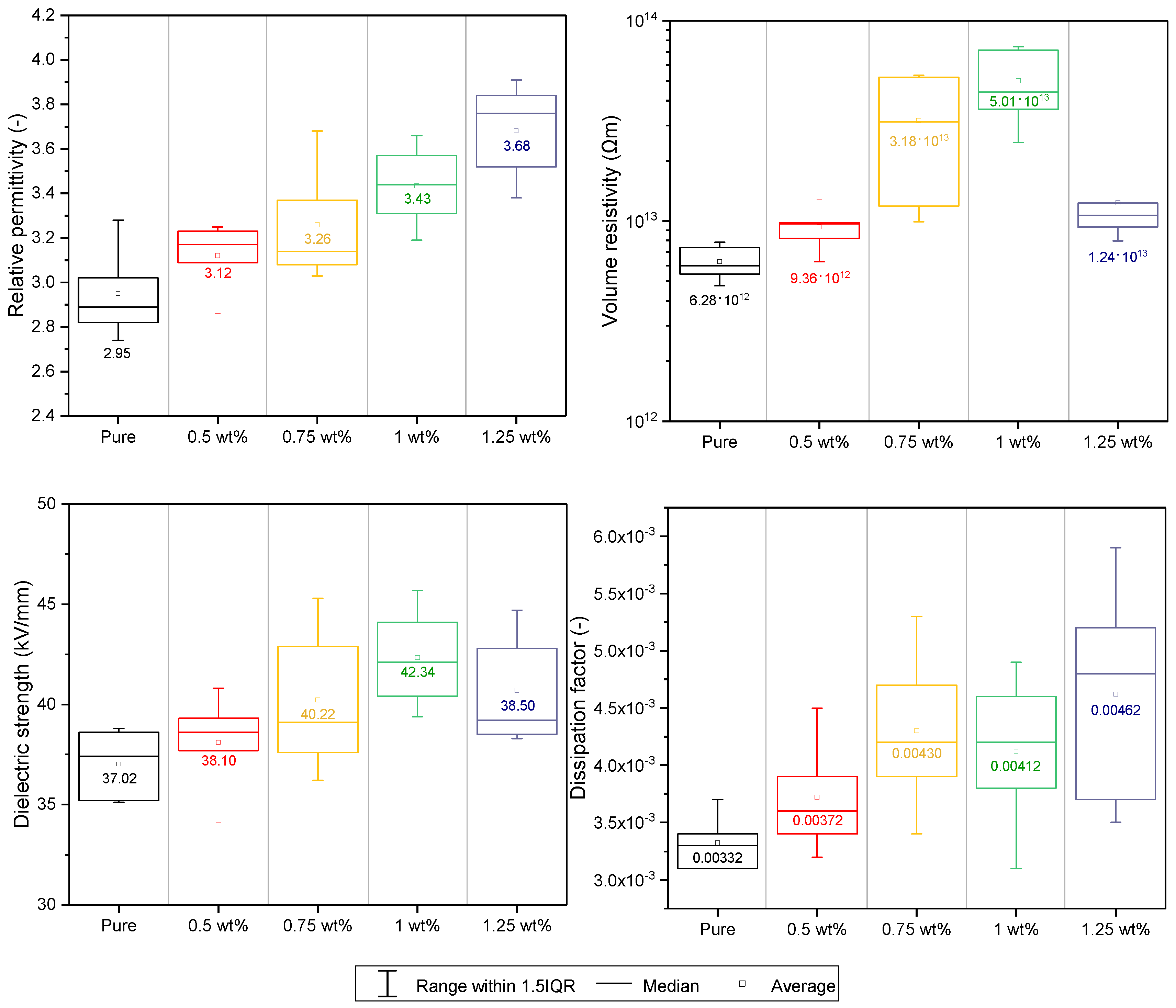
Taking into account the preliminary measurements of the main electrical properties, which are deeply described in [32], the optimum weight ratio was set to 1%. Especially due to the values of dielectric strength and volume resistivity. The box plots with marked average values of investigated parameters are shown in Figure 5.
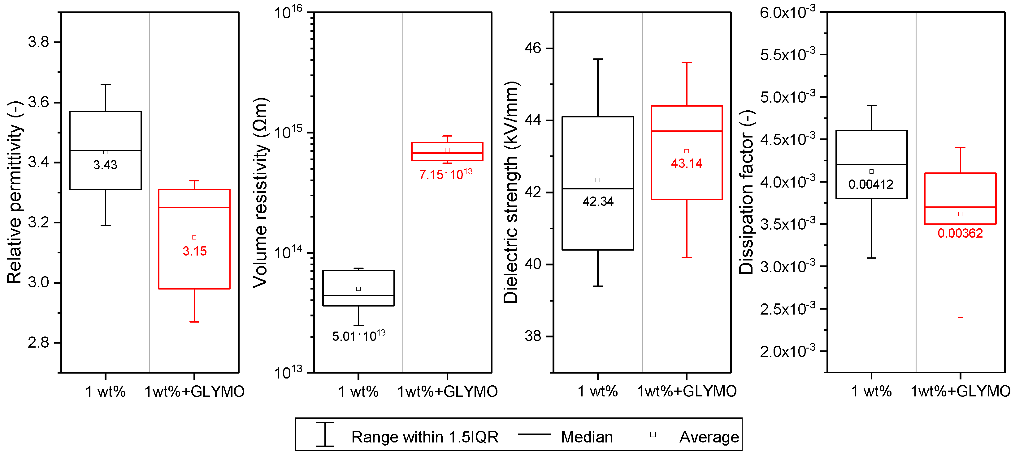
For the improvement of the mixability between filler and matrix, the silane coupling agent γ -glycidoxypropyltrimethoxysilane (Sigma-Aldrich) has been selected, hereinafter referred to as GLYMO. It is an epoxisilane coupling agent, specifically an organofunctional trialkoxisilane utilizing high reactivity between epoxy rings and amino groups [34]. The optimal amount of coupling agent depending on its and filler properties and it has been calculated to 18.12% of filler weight. The effect of addition of surface coupling agent is presented on selected dielectric parameters (Figure 6).
As has been already mentioned, more detailed information about the MgO, its dielectric properties and possibilities of surface modification by γ -glycidoxypropyltrimethoxysilane could be found in our previous studies [32,35].

2.3. Reinforcement

The reinforcement, or carrier component, is understood to mean the part of the composite material having primarily the task of increasing the mechanical strength and stiffness of the material [36]. In electrical applications, the reinforcement may also behave partially as a dielectric barrier. This is especially valid for systems containing a film reinforcements.
Currently, the market has a relatively wide range of reinforcements. Especially woven, film, foil or fiber reinforcements are used for electrotechnical applications.
The most interesting choice for the synthesized material was the polyethylene naphthalate (PEN) film Teonex Q51 (Teijin DuPont) of a nominal thickness of 25 μ m. This material ensures the high electrical strength of the resulting composite. The electrical strength of the PEN Teonex Q51 film is 300 kV/mm (valid for 25 μ m) [37].
In general, polyethylene naphthalate is a linear polyester with excellent electrical and mechanical properties. The basic materials for its production are naphthalene dicarboxilic acid and ethylene glycol [38]. Compared to PET, which is commonly used as a reinforcement, PEN exhibits significantly better properties. These are higher chemical and hydrolytic resistance, higher Young’s modulus, lower oligomer extraction, and higher glass transition temperature [39,40,41,42]. These different material properties are due to differences in chemical structure. While PET contains terephthalic acid, which has only one benzene nucleus, PEN contains naphthalene dicarboxylic acid, which has two linked benzene nuclei (naphthalene) [39]. Due to its considerably better properties, it becomes a suitable substitute for commonly used polyethylene terephthalate, not only in the electrical industry [43].

2.4. Synthesis of Nanostructured Micaless Microcomposite

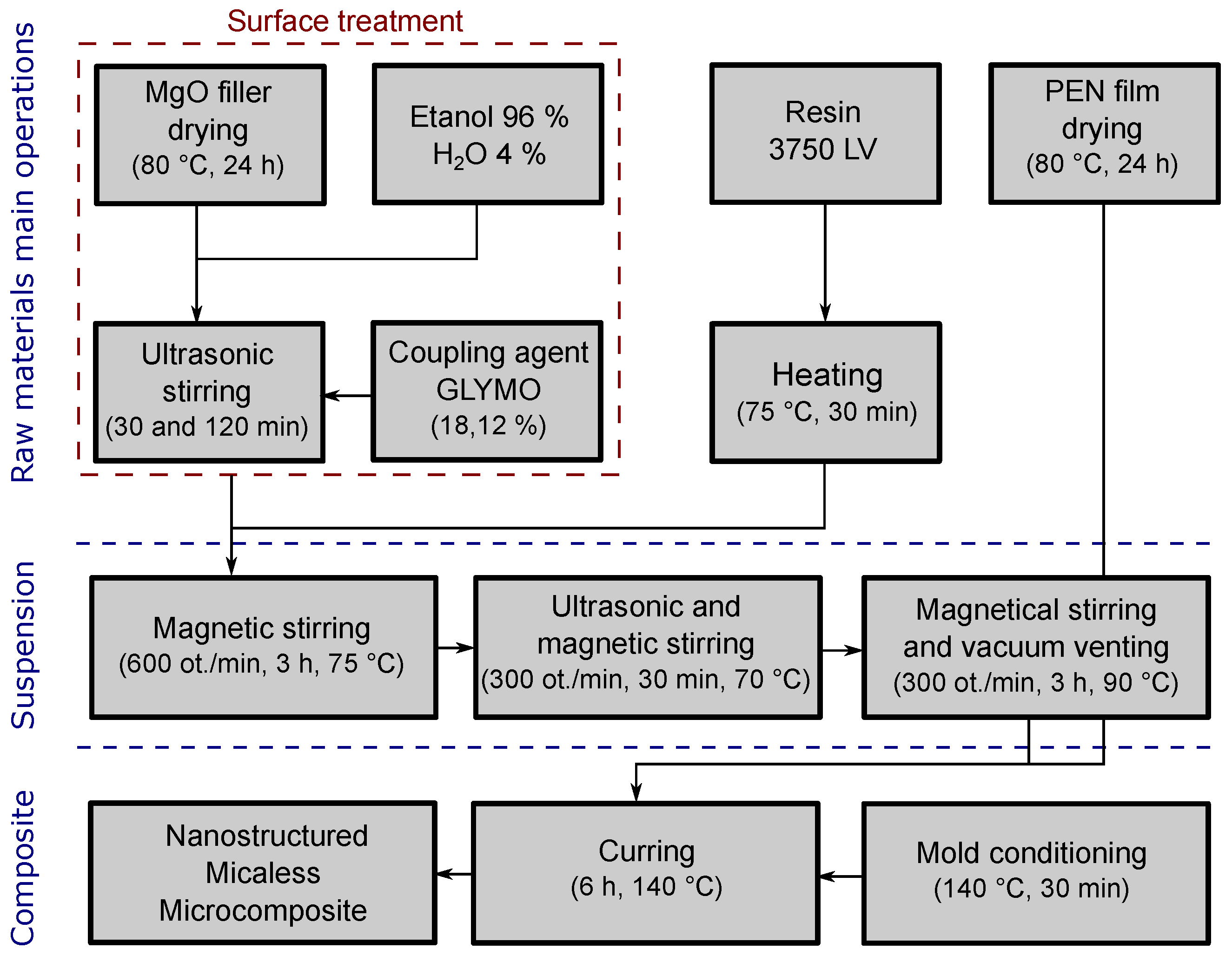
In the previous parts, individual components, dielectric properties and their application advantages were described. In this section, attention will be paid to the description of the production process of synthesized composite material. It can be divided into several phases, which are shown in block diagram in Figure 7.
In general, particles or films often contain a significant amount of water molecules which are absorbed or weakly bonded in the volume. From this reason, it is necessary to start with the dehydration. Magnesium oxide powder placed in Petri dishes was dried in a hot air dryer together with sheets of polyethylene naphthalate film (80 °C, 24 h) to eliminate the effect of moisture. After that, the particles were added to a solution of 96% ethanol 4% H2O (10 mL) and ultrasonic stirred (20 kHz, 30 min). The surface functionalization process follows with addition of GLYMO modifier (18.12%) to the mixture with re-application of ultrasonic stirring (20 kHz, 2 h). Meanwhile, the epoxy resin was heated to a temperature of 75 °C, which resulted in a lower viscosity for subsequent processing. The surface-treated (ST) nanoparticles were then added to the already heated epoxy resin and subsequently magnetically stirred (600 rpm, 3 h, 75 °C). Last but one step was combined ultrasonic and magnetical stirring (300 rpm, 20 kHz, 30 min, 70 °C). Finally, vacuum venting was performed with reduced magnetic stirring (300 rpm, 3 h, 90 °C). The elevated temperature of 90 °C provided evaporation of the ethanol from the epoxy mixture. The resultant mixture was then applied to preheated Teflon molds with a silicone spacer and a PEN reinforcing component. Preheating of Teflon molds eliminates the effect of their surface moisture and ensures better adhesion of the silicone spacer. Considerable attention has been also paid during production to ensuring the homogeneity of the internal structure of the sample by removing the resulting air bubbles. The prepared samples have been cured in a hot air dryer (140 °C, 6 h).

2.5. X-ray Diffraction Analyses of Synthesized and Commonly Used Composites

The X-ray diffraction measurement has been used for material identification [32,44]. These measurements have been performed on a Panalytical X’Pert Pro (Malvern Panalytical) automated powder X-ray diffractometer using an X-ray lamp (IKa1 = 0.154 nm, 40 kV, 30 mA) and a semiconductor ultra-rapid PIXcel detector in the geometric Bragg-Bretan arrangement.
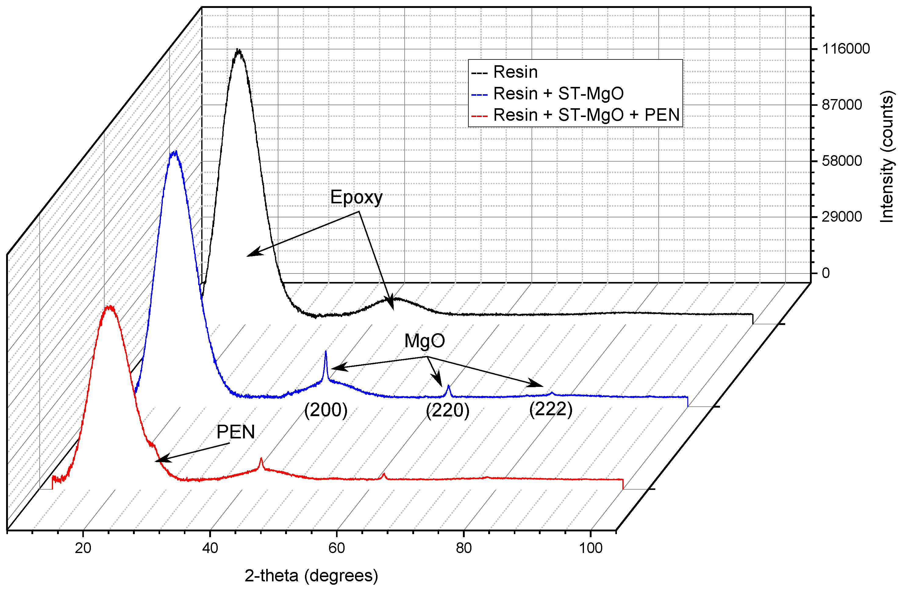
From the X-ray diffraction analysis is visible the character of the amorphous material (matrix). This symbolizes very wide diffraction (6–8 degrees in the diffraction angles 2-theta), which are shown in Figure 8.
These diffractions, resp. their positions on the x-axis, corresponding with the results of presented studies [45,46]. On this diffractogram, only the diffraction pattern of MgO (200), (220) and (222) are noticed. Other lines are weak, or we do not notice them at all. Analysis of the profile of diffraction lines (200) showed that the size of the coherent dispersion region of X-ray crystallization (crystallite) is in all cases about 23–25 nm and the micro-deformation is relatively low (0.0022–0.0025). This fact corresponds to the knowledge of the average size of nanofillers from manufacturer [31].
From the results of synthesized nanostructured microcomposite is obvious difference in the area of the first wide diffraction of the epoxy matrix and also in the decrease in the diffraction lines of the magnesium oxide in comparison with pure epoxy resin and resin with dispersed MgO, respectively. When comparing the position of this diffraction change with study [47], the behavior corresponding to the polyethylene naphthalate (about 26 degrees in the range of 2-theta diffraction angles). Decreases in the intensity of individual diffractions are due to the presence of PEN foil and it indicates that the volume ratios of composite have been changed.
The attention has been also paid to the analysis of commonly used insulation materials. There are visible peaks of used filler, which corresponds to Muscovite 6-263(2M1) whose has been investigated e.g., in [48]. Unfortunately, due to the majority share of mica paper in composite and its intensity, it is not possible to define other elements using this technique. However, slight differences between glass reinforced composite and PET reinforced composite are visible in Figure 9.

3. Methods

In the following sections, the methods and measurement setups are described. The collection of 3–5 samples were used for each measurement. Flat samples have a square shape and dimensions depending on the requirments of the selected method (100 × 100 mm or 40 × 40 mm).

3.1. Key Dielectric Parameters

The most important dielectric parameters has been investigated for synthesized nanostructured micaless microcomposite. Namely dissipation factor (IEC 60250:1969 [49]), dielectric strength (IEC 60243-1:2013 [50]) and volume resistivity (IEC 62631-3-2:2015 [51]) were measured according to mentioned standards. All measurements were performed according to Standard conditions given by IEC 60212:2010 [52]. The test conditions are mentioned in the Table 1.

3.2. Broadband Dielectric Spectroscopy

Broadband Dielectric Spectroscopy (BDS) is a modern diagnostic method which allows interconnecting several measurement techniques to obtain a comprehensive view of the material behavior under an electric field with a frequency in a very wide range. For this investigation, the main diagnostic unit of the Alpha-A measuring device (Novocontrol Technologies) has been used. It contains a frequency response analyzer with a sinusoidal signal generator. The presented analysis was performed in the temperature range from −50 °C to 60 °C and in the frequency range from 0.5 Hz to 1 MHz.

3.3. Resorption Current Analysis

The aim of this section is to introduce the methods of dielectric resorption analysis. Namely a method of determination of the area over the curve and the method of the tangent curve determination. These procedures are presented in publication [53] in connection with the analysis of dielectric absorption. However, in this case, it will be used for analyses of the behavior after DC voltage disconnection.
The electrometer Keithley 6517A (Keithley Instruments) with 8009 Resistivity Fixture (Keithley Instruments) electrode system were used for this measurement (schematicaly in Figure 10a). The measurement starts with the charging (3600 s) and after that, the dielectric resorption current was measured from 0 to 300 s. For better comparison between individual composite materials, both parameters have been determined at the applied intensity of electric field 1 kV/mm. In the following text, the main ideas of above-mentioned techniques will be described.
Area over the curve gives also the information about the ability of the material release accumulated charge that has been accumulated inside the material structure due to the DC voltage application. Whereas the interval was set within the range of 0 to 300 s, it also allows the inclusion of dielectric resorption in the time immediately after disconnection from DC voltage source. Graphical description of mathematical processing is illustrated in Figure 10b. Because there are discrete values of the resorption current, the area above curve can be defined as an area of few trapezoids.
In the context of measurement, the data can be analyzed by another technique. The time constant of the dielectric, which is given by multiplicity of the resistance and the capacitance dielectric, can be determined by the construction of the tangent curve (Figure 10c).

3.4. Partial Discharges Measurement

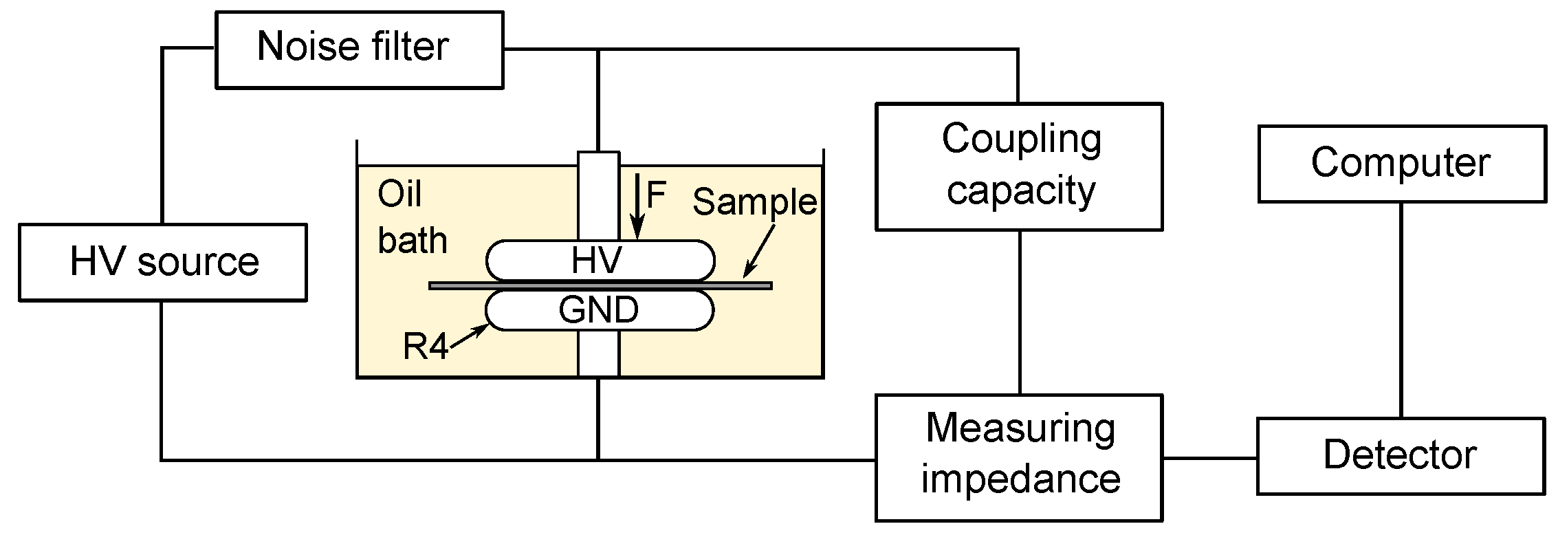
The experimental measurement was carried out using a galvanic measurement method in accordance with IEC EN 60270 standard [54] with a parallel measuring impedance (Figure 11). The measured samples have been immersed in an oil bath for the elimination of surface discharges which could overlap the internal discharge activity [55,56]. High voltage source 200 kV (High Volt), coupling capacity 1000 pF ± 10% (Maxwell Technologies), measuring impedance LDM-5 U 50 Ω (LDIC), measuring and evaluation device PD Smart (Doble Lemke), pulse calibrator LDC-5/S3 (LDIC) and electrode with rounded edge limiting the effect of corona discharges have been used for this investigation. For better comparison, the inception voltage was replaced by the inception level (kV/mm). Values of charge Qiec (pC) have been determined at the inception level after 60 s. Following the results of the measurements, the comparison at the level 18.5 kV/mm has been performed.

4. Results and Discussion

In this section, the results achieved by previously describes methods are presented and discussed. The synthesized nanostructured micaless microcomposite is compared with two commonly used insulation systems [57,58] for verification of its properties.

4.1. Key Dielectric Parameters

The key dielectric parameters have been investigated according to the above-mentioned standards and test conditions (Table 1) at Standard conditions B given by IEC 60212:2010. From the probability plots (Figure 12) is visible that the measured values show a low level of variability. There are also noted major statistical parameters, like average value ( μ ), standard deviation ( σ ) and coefficient of variation ( θ ).
For the comparison with the study of Harvanek [28] is necessary also included minimum measured values (maximum value for dissipation factor). These values are shown in Table 2. From this comparison, it is clear that the synthesized material (marked A) exceeds in all cases commonly used composite materials contains mica paper (PET reinforced mica composite marked B, Glass reinforced mica composite marked C). It confirms the appropriate selection of individual components of the synthesized nanostructured micaless microcomposite.
There is visible that the minimal dielectric strength of film reinforced composites (A, B) is relatively equal, but higher for synthesized nanostructured micaless microcomposite. It is caused by the compact character of the reinforced component, which fulfills the role of a dielectric barrier next to the reinforcing [59]. The positive effect of a polymer film on dielectric properties is also mentioned by the authors of the studies [60,61].
Other parameters are influenced by the internal structure of the composite, where primarily calcined mica paper contributes to dielectric losses by its strongly inhomogeneous structure, even though it is composed of smaller platelets than non-calcined mica paper [62]. By introducing the MgO into epoxy resin, the different energy levels are achieved. It resulting in the differences in dielectric losses and volume resistivity.

4.2. Broadband Dielectric Spectroscopy

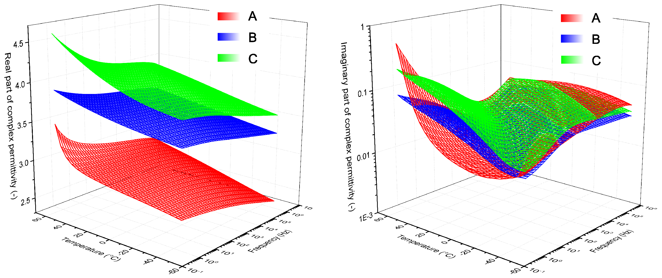
It is evident from the results (Figure 13) that the synthesized material (A) shows the stability of the real part of complex permittivity and its value is lower in comparison with commonly used insulation systems (B, C). This fact is very important for potential application in the industry. The lower value of real part of complex permittivity, which represents relative permittivity of insulation could cause lower local overloading if the delamination occurs. This fact can be easily illustrated by using of Maxwell-Wagner model for double layer insulator. In the case of presence e.g., air-filled delamination, the maximal field strength in the cavity is lower if the surrounding material has also lower permittivity.
If the attention is focused on the dielectric processes it is very difficult to precisely define the individual polarizations which are visible in the imaginary part of the complex permittivity, because there is a combination of thermoplastic reinforcement with a thermosetting resin. However, these polarizations are probably caused due to the local motion of small molecular units, side chains and aromatic substitution groups, which contribute slightly to the dielectric losses [63,64] or due to the Brownian motion of the chain segments [65] in the case of higher temperatures. In the case of a loss factor, it is visible that the surfaces of investigated materials overlap to a large extent.

4.3. Resorption Current Analysis

Resorption current analysis brings an interesting view on the response of internal structure after DC voltage application. It is evident from the results (Table 3) that the proposed nanostructured microcomposite has the highest ability to dissipate the accumulated charge in the internal structure after disconnection from the DC voltage source. This difference can be attributed to the substitution of the highly inhomogeneous mica paper interface with the nanometric magnesium oxide filler at optimal weight ratio. Another reason is to increase the density of deep electron traps, in which the captured charge carriers can easily recombine [66,67]. This fact is strongly connected with conductivity of material. It is based on the Poole-Frenkel mechanism, wherein the deep traps enhance the height of energy barriers [68]. From this reason, the introduction of deep traps could be considered more helpful for insulating materials than shallow traps [69].

4.4. Partial Discharges Measurement

The partial discharges (PDs) are one of the most occurring phenomena in composite insulation systems, especially in rotating machines. From this reason, the PD inception level and charge Qiec has been investigated. The obtained results are shown in Table 4.
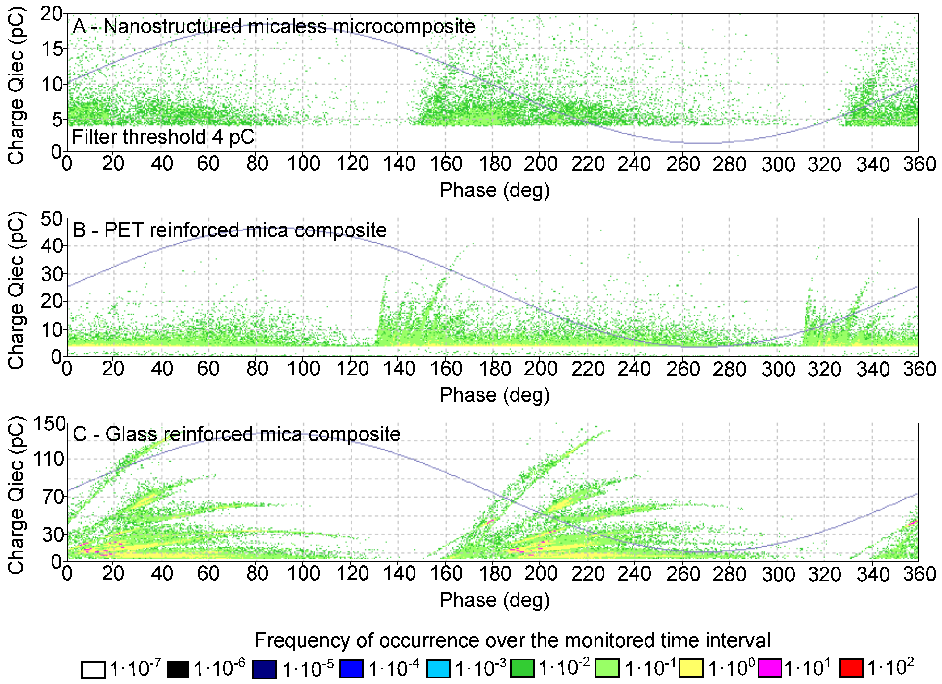
The character of the discharge activity at comparative level of 18.5 kV/mm is shown in the form of Phase Resolved Partial Discharges (PRPD) diagrams (Figure 14). From these diagrams, it is evident that their character corresponds with the internal partial discharges. There are also very well visible the movements of the “rabbit ear” [70] during the changes of the applied voltage, which are indicators for void [71] partial discharges. The difference in discharge activity could be attributed to the strong inhomogeneity of the internal structure or imperfect adhesion between the various parts of commonly used composite materials. Here, small, gas-filled areas near fibres, film or mica paper could occur during the process of producing the insulating system [72,73,74].

5. Conclusions

In this paper, new nanostructured micaless microcomposite insulation material has been synthesized and diagnosed. The basis of the synthesized material is Epoxilite 3750 LV solvent-free epoxy resin, which is commonly used in industry to impregnate rotating machines. Mainly due to its low viscosity and high bond strength. The better properties of epoxy resin have been achived by the addition of optimum amount of magnesium oxide filler. This was set according to preliminary tests of dielectric parameters. Magnesium oxide is a simple oxide with the highest internal resistivity of commonly used oxides. Polyethylene naphthalate film was used as a reinforcement mostly for the reason to increase dielectric strength of whole composite.
The synthesized nanostructured micaless microcomposite has been also subjected to different diagnostic methods. All of these tests have been performed for two representatives of commonly used three-component systems for comparison. From this investigation is evident, that there is a possibility of eliminating the mica paper, which could lead to better insulation properties.

Author Contributions

Conceptualization, J.H. and P.T.; methodology, J.H.; validation, V.M. and P.T.; formal analysis, P.T.; investigation, J.H. and P.Š.; resources, J.H., P.T. and V.M.; data curation, J.H. and P.T.; writing—original draft preparation, J.H.; writing—review and editing, P.T., V.M. and P.Š.; visualization, J.H.; supervision, P.T. and V.M.

Funding

This research has been supported by the Ministry of Education, Youth and Sports of the Czech Republic under the project OP VVV Electrical Engineering Technologies with High-Level of Embedded Intelligence CZ.02.1.01/0.0/0.0/18_069/0009855 and by the Student Grant Agency of the West Bohemia University in Pilsen, grant No. SGS-2018-016 Diagnostics and materials in electrotechnics.

Acknowledgments

Authors would like to thanks Petr Kadlec and Martin Hirman for experimental help.

Conflicts of Interest

The authors declare no conflict of interest.

Abbreviations

The following abbreviations are used in this manuscript:
BDSBroadband Dielectric Spectroscopy
GLYMO γ -glycidoxypropyltrimethoxysilane
PENPolyethylene napthalate
PETPolyethylene terepthalate
PDsPartial Discharges
PRPDPhase Resolved Partial Discharge
STSurface-treated
VPIVacuum Pressure Impregnation
XRDX-ray Diffraction

References

  1. Mentlik, V.; Trnka, P.; Sasek, L.; Trnkova, M. Spolehlivostni Aspekty Elektrotechnologie; BEN - Technická Literatura: Praha, Czech Republic, 2011; ISBN 978-80-7300-4. [Google Scholar]
  2. Hornak, J. Interaction of Inhomogeneous Dielectric with an Electric Field. Ph.D. Thesis, University of West Bohemia, Pilsen, Czech Republic, 2018. [Google Scholar]
  3. Wang, W.; Yang, Y. The synergistic effects of the micro and nano particles in micro-nano composites on enhancing the resistance to electrical tree degradation. Sci. Rep. 2017, 7, 8762–8781. [Google Scholar] [CrossRef] [PubMed]
  4. Chung, D.D.L. Composite Materials: Science and Applications; Springer: New York, NY, USA, 2010; ISBN 978-1-84882-830-8. [Google Scholar]
  5. Laffoon, C.M.; Hill, C.F.; Moses, G.L.; Berberich, L.J. A new high-voltage insulation for turbine-generator stator windings. Trans. Am. Inst. Elect. Eng. 1951, 70, 721–730. [Google Scholar] [CrossRef]
  6. Boulter, E.A.; Stone, G.C. Historical development of rotor and stator winding insulation materials and systems. IEEE Electr. Insul. Mag. 2004, 20, 25–39. [Google Scholar] [CrossRef]
  7. Oburger, W. Die Isolierstoffe der Elektrotechnik; Springer: Berlin, Germany, 1957; ISBN 978-3-662-24084-7. [Google Scholar]
  8. Roth, A. Hochspannungstechnik; Springer: Vienna, Austria, 1959; ISBN 978-3-7091-3903-5. [Google Scholar]
  9. Andraschek, N.; Wanner, A.; Ebner, C.; Riess, G. Mica/epoxy-composites in the electrical industry: Applications, composites for insulation, and investigations on failure mechanisms for prospective optimizations. Polymers 2016, 8, 201. [Google Scholar] [CrossRef] [PubMed]
  10. Goetter, R.; Winkeler, M. New developments in unsaturated polyester resins used for electrical insulation. In Proceedings of the Electrical Insulation Conference and Electrical Manufacturing and Coil Winding Conference, Cincinnati, OH, USA, 16–18 October 2001; pp. 51–56. [Google Scholar] [CrossRef]
  11. Jia, Z.; Hao, Y.; Xie, H. The degradation assessment of epoxy/mica insulation under multi-stresses aging. IEEE Electr. Insul. Mag. 2006, 13, 415–422. [Google Scholar] [CrossRef]
  12. Miller, G.H. Silicone resin rich mica paper laminates for class H operation and radiation resistance. In Proceedings of the 1975 EIC 12th Electrical/Electronics Insulation Conference, Boston MA, USA, 11–14 November 1975; pp. 273–275. [Google Scholar] [CrossRef]
  13. Grubelnik, W.; Roberts, J.; Koerbler, B.; Marek, P. A new approach in insulation systems for rotating machines. In Proceedings of the Electrical Insulation Conference and Electrical Manufacturing Expo, Indianapolis, IN, USA, 23–26 October 2005; pp. 97–102. [Google Scholar] [CrossRef]
  14. Johnston, D.R.; Markovitz, M. Corona-Resistant Insulation, Electrical Conductors Covered Therewith and Dynamoelectric Machines and Transformers Incorporating Components of Such Insulated Conductors. U.S. Patent 4760296, 26 July 1988. [Google Scholar]
  15. Lewis, T.J. Nanometric dielectrics. IEEE Trans. Dielectr. Electr. Insul. 1994, 1, 812–825. [Google Scholar] [CrossRef]
  16. Tanaka, T.; Imai, T. Advances in nanodielectric materials over the past 50 years. IEEE Electr. Insul. Mag. 2013, 29, 10–23. [Google Scholar] [CrossRef]
  17. Luisetto, I.; Tuti, S.; Marconi, E.; Veroli, A.; Buzzin, A.; De Cesare, G.; Natali, S.; Verotti, M.; Giovine, E.; Belfiore, N.P. An Interdisciplinary Approach to the Nanomanipulation of SiO2 Nanoparticles: Design, Fabrication and Feasibility. Appl. Sci. 2018, 8, 2645. [Google Scholar] [CrossRef]
  18. Hao, J.; Li, Y.; Liao, R.; Liu, G.; Liao, Q.; Tang, C. Fabrication of Al2O3 Nano-Structure Functional Film on a Cellulose Insulation Polymer Surface and Its Space Charge Suppression Effect. Polymers 2017, 9, 502. [Google Scholar] [CrossRef]
  19. Ali, H.S.; Alghamdi, A.S.; Murtaza, G.; Arif, H.S.; Naeem, W.; Farid, G.; Sharif, S.; Ashiq, M.G.B.; Shabbir, S.A. Facile Microemulsion Synthesis of Vanadium-Doped ZnO Nanoparticles to Analyze the Compositional, Optical, and Electronic Properties. Materials 2019, 12, 821. [Google Scholar] [CrossRef]
  20. Imai, T.; Sawa, F.; Ozaki, T.; Inoue, Y.; Shimizu, T.; Tanaka, T. Roles of fillers on properties of nano-TiO2 and Micro-SiO2 filler mixed composites. In Proceedings of the 2007 IEEE International Conference on Solid Dielectrics, Winchester, UK, 8–13 July 2007; pp. 407–410. [Google Scholar] [CrossRef]
  21. Andritsch, T.; Kochetov, R.; Morshuis, P.H.F.; Smit, J.J. Dielectric properties and space charge behavior of MgO-epoxy nanocomposites. In Proceedings of the 2010 10th IEEE International Conference on Solid Dielectrics, Potsdam, Germany, 4–9 July 2010; pp. 1–4. [Google Scholar] [CrossRef]
  22. Vesely, O.; Mentlik, V. Cable insulation properties changes through nanofillers: Nanoclays as a counterpart to the traditional fire retardants. In Proceedings of the 2016 17th International Scientific Conference on Electric Power Engineering, Prague, Czech Republic, 16–18 May 2016; pp. 1–4. [Google Scholar] [CrossRef]
  23. Polansky, R.; Kadlec, P.; Kolska, Z.; Svorcik, V. Influence of dehydration on the dielectric and structural properties of organically modified montmorillonite and halloysite nanotubes. Appl. Clay Sci. 2017, 147, 19–27. [Google Scholar] [CrossRef]
  24. Harvanek, L.; Mentlik, V. New complex nanocomposite DGEBA. In Proceedings of the 2016 Conference on Diagnostics in Electrical Engineering, Pilsen, Czech Republic, 6–8 September 2016; pp. 1–4. [Google Scholar] [CrossRef]
  25. Mentlik, V.; Michal, O. Influence of SiO2 nanoparticles and nanofibrous filler on the dielectric properties of epoxy-based composites. Mater. Lett. 2018, 223, 41–44. [Google Scholar] [CrossRef]
  26. Polansky, R.; Prosr, P.; Zemanova, M.; Pihera, J.; Dzugan, T.; Chvojka, J. Electrospun nanofibres as a tool for controlling the gas bubble size distribution in fibre/thermoset-matrix composites. Compos. Sci. Technol. 2018, 163, 96–104. [Google Scholar] [CrossRef]
  27. Totten, G.E.; Mackenzie, D.S. Handbook of Aluminum; Marcel Dekker: New York, NY, USA, 2003. [Google Scholar]
  28. Harvanek, L. Nanomaterials for Electrotechnic. Ph.D. Thesis, University of West Bohemia, Pilsen, Czech Republic, 2017. [Google Scholar]
  29. Product Information - Epoxylite ®, 3750 LV, Elantas ®; Italia S.r.l.: Collechion, Italy, 2009.
  30. Ceresana. Market Study: Fillers, 4th ed.; Ceresana: Constance, Germany, 2016. [Google Scholar]
  31. Magnesium Oxide (MgO, 99+%, 20 nm). Available online: www.nanoamor.com/inc/sdetail/11013/2543 (accessed on 26 March 2019).
  32. Hornak, J.; Trnka, P.; Kadlec, P.; Michal, O.; Mentlik, V.; Sutta, P.; Csanyi, G.M.; Tamus, Z.A. Magnesium Oxide Nanoparticles: Dielectric Properties, Surface Functionalization and Improvement of Epoxy-Based Composites Insulating Properties. Nanomaterials 2018, 8, 381. [Google Scholar] [CrossRef] [PubMed]
  33. Marfunin, A.S. Advanced Mineralogy: Volume 1 Composition, Structure, and Properties of Mineral Matter: Concepts, Results, and Problems; Springer: Berlin/Heidelberg, Germany, 1994; ISBN 978-3-642-78525-2. [Google Scholar]
  34. Mittal, K.L. Silanes and Other Coupling Agents; VSP: Leiden, The Netherland, 2009; ISBN 9789004165915. [Google Scholar]
  35. Hornak, J.; Mentlik, V.; Gutten, M. Vliv funkcionalizace povrchu oxidu hořečnatého na dielektrické vlastnosti kompozitního dielektrika. Chemické Listy 2018, 112, 246–249. [Google Scholar]
  36. Lee, S.M. Handbook of Composite Reinforcements; John Wiley: Hoboken, NJ, USA, 1992; ISBN 978-0471188612. [Google Scholar]
  37. Teijing DuPont Films Japan. Teonex® Q51. Available online: https://www.teijinfilmsolutions.jp/english/product/pen_teo.html (accessed on 26 March 2019).
  38. Lee, K.K.; Cho, B.H.; Kim, Y.W. Process for Preparing Polyethylene Naphthalate. U.S. Pattent 5294695, 15 March 1994. [Google Scholar]
  39. Anderson, D.W.; Handa, M. Effects of CFC and HFC refrigerants and ester lubricants on polyester insulation materials. In Proceedings of the Electrical Electronics Insulation Conference and Electrical Manufacturing & Coil Winding Conference, Rosemont, IL, USA, 18–21 September 1995; pp. 431–435. [Google Scholar] [CrossRef]
  40. Zhang, H.; Ward, I.M. Kinetics of hydrolytic degradation of poly(ethylene naphthalene-2,6-dicarboxylate). Macromolecules 1995, 28, 7622–7629. [Google Scholar] [CrossRef]
  41. Sadanobu, J.; Inata, H. The properties of poly(ethylene naphthalate) (PEN) and its application. In Science and Technology of Polymers and Advanced Materials; Paras, N., Prasad, P.N., Mark, J.E., Kandil, S.H., Kafafi, Z.H., Eds.; Springer: Boston, MA, USA, 1998; pp. 141–151. ISBN 978-1-4899-0114-9. [Google Scholar]
  42. Hine, P.J.; Astruc, A.; Ward, I.M. Hot compaction of polyethylene naphthalate. J. Appl. Polym. Sci. 2004, 93, 796–802. [Google Scholar] [CrossRef]
  43. Lillwitz, L.D. Production of dimethyl-2,6-naphthalenedicarboxylate: Precursor to polyethylene naphthalate. Appl. Catal. A 2001, 221, 337–358. [Google Scholar] [CrossRef]
  44. Giannini, C.; Ladisa, M.; Altamura, D.; Siliqi, D.; Sibillano, T.; De Caro, L. X-ray diffraction: A powerful technique for the multiple-length-scale structural analysis of nanomaterials. Crystals 2016, 6, 87. [Google Scholar] [CrossRef]
  45. Kherzi, T.; Sharif, M.; Pourabas, B. Polythiophene-graphene oxide doped epoxy resin nanocomposites with enhanced electrical, mechanical and thermal properties. RSC Adv. 2016, 6, 93680–93693. [Google Scholar] [CrossRef]
  46. Abdullah, S.I.; Ansari, M.N.M. Mechanical properties of grapheme oxide (GO)/epoxy composites. HBRC J. 2015, 11, 151–156. [Google Scholar] [CrossRef]
  47. Blanton, T.N. An X-ray diffraction study of poly(ethylene-2,6-naphthalate), PEN. Powder Diffr. 2002, 17, 125–131. [Google Scholar] [CrossRef]
  48. Arif, M.; Moon, C.J. Nickel-rich chromian muscovite from the Indus suture ophiolite, NW Pakistan: Implications for emerald genesis and exploration. Biochem. J. 2007, 11, 475–482. [Google Scholar] [CrossRef]
  49. IEC. Recommended Methods for the Determination of the Permittivity and Dielectric Dissipation Factor of Electrical Insulating Materials at Power, Audio and Radio Frequencies Including Metre Wavelengths; IEC 60250:1969; International Electrotechnical Commission: Geneva, Switzerland, 1969. [Google Scholar]
  50. IEC. Methods of Test for Electric Strength of Solid Insulating Materials; IEC 60243-1:2013; International Electrotechnical Commission: Geneva, Switzerland, 2013. [Google Scholar]
  51. IEC. Dielectric and Resistive Properties of Solid Insulating Materials—Part 3-2: Determination of Resistive Properties (DC methods); IEC 62631-3-2:2015; International Electrotechnical Commission: Geneva, Switzerland, 2015. [Google Scholar]
  52. IEC. Standard Conditions for Use Prior to and During the Testing of Solid Electrical Insulating Materials; IEC 60212:2010; International Electrotechnical Commission: Geneva, Switzerland, 2010. [Google Scholar]
  53. Mentlik, V.; Pihera, J.; Polansky, R.; Prosr, P.; Trnka, P. Diagnostika Elektrických Zařízení; BEN - Technická Literatura: Praha, Czech Republic, 2008; ISBN 978-80-7300-232-9. [Google Scholar]
  54. IEC. High-Voltage Test Techniques—Partial Discharge Measurements; IEC 60270:2010; International Electrotechnical Commission: Geneva, Switzerland, 2015. [Google Scholar]
  55. Herath, H.M.M.G.T.; Kumara, J.R.S.S.; Fernando, M.A.R.M.; Bandara, K.M.K.S.; Serina, I. Comparison of supervised machine learning techniques for PD classification in generator insulation. In Proceedings of the 2017 IEEE International Conference on Industrial and Information Systems (ICIIS), Peradeniya, Sri Lanka, 15–16 December 2017; pp. 1–6. [Google Scholar] [CrossRef]
  56. Hui Ma, J.; Chan, C.; Saha, T.K. Ekanayake, Ch. Pattern recognition techniques and their applications for automatic classification of artificial partial discharge sources. IEEE Trans. Dielectr. Electr. Insul. 2013, 20, 468–478. [Google Scholar] [CrossRef]
  57. General Description. Relastik® 45.013: Flexible Mica Foils; Cogebi, Member of Elinar Group: Tabor, Czech Republic, 2012. [Google Scholar]
  58. General Description. Relanex® 45.011: Flexible Mica Tapes and Foils; Cogebi, Member of Elinar Group: Tabor, Czech Republic, 2012. [Google Scholar]
  59. Zeng, C.P. Novel butt-lapped PET-mica tape turn insulation for high voltage motors. IEEE Electr. Insul. Mag. 2015, 31, 36–42. [Google Scholar] [CrossRef]
  60. Nurse, J.A. Development of modern high-voltage insulation systems for large motors and generators. Power Eng. J. 1998, 3, 125–130. [Google Scholar] [CrossRef]
  61. Neal, J.E. The use of polyester film in HV rotating machine insulation. In Proceedings of the 1995 Electrical Electronics Insulation Conference and Electrical Manufacturing & Coil Winding Conference (EEIC), Rosemont, IL, USA, 18–21 September 1995; pp. 583–587. [Google Scholar] [CrossRef]
  62. Stone, G.C.; Boulter, E.A.; Culbert, I.; Dhirani, H. Electrical Insulation for Rotating Machines: Design, Evaluation, Aging, Testing, and Repair; John Wiley & Sons: Hoboken, NJ, USA, 2004; ISBN 9780471682899. [Google Scholar]
  63. Wang, O.B.; Jang, K.U.; Lee, J.O.; Baek, Y.H. Thermally stimulated current of epoxy composites due to structural change and interfacial state. In Proceedings of the 1994 4th International Conference on Properties and Applications of Dielectric Materials (ICPADM), Brisbane, Australia, 3–8 July 1994; pp. 290–293. [Google Scholar] [CrossRef]
  64. Ulrych, J.; Polansky, R.; Pihera, J. Dielectric analysis of polyethylene terephthalate (PET) and polyethylene naphthalate (PEN) films. In Proceedings of the 2014 15th International Scientific Conference on Electric Power Engineering (EPE), Brno, Czech Republic, 12–14 May 2014; pp. 411–415. [Google Scholar] [CrossRef]
  65. Hardy, L.; Fritz, A.; Stevenson, I.; Boiteux, G.; Seytre, G.; Schönhals, A. Dielectric relaxation behaviour of poly(ethylene naphthalene 2,6 dicarboxylate) (PEN). J. Non-Cryst. Solids 2002, 305, 174–182. [Google Scholar] [CrossRef]
  66. Zepeng, L.V.; Wang, X.; Wu, K.; Chen, X.; Cheng, Y.; Dissado, L.A. Dependence of charge accumulation on sample thickness in Nano-SiO2 doped LDPE. IEEE Trans. Dielectr. Electr. Insul. 2013, 20, 337–345. [Google Scholar] [CrossRef]
  67. Tanaka, T.; Imai, T. Advanced Nanodielectrics: Fundamentals and Application; Pan Stanford: Singapore, 2017; ISBN 9814745022. [Google Scholar]
  68. Wang, W.; Min, D.; Li, S. Understanding the conduction and breakdown properties of polyethylene nanodielectrics: Effect of deep traps. IEEE Trans. Dielectr. Electr. Insul. 2016, 23, 564–572. [Google Scholar] [CrossRef]
  69. Kubyshkina, E. Ab Initio Modelling of Interfaces in Nanocomposites for High Voltage Insulation. Ph.D. Thesis, KTH Royal Institute of Technology, Stockholm, Sweden, 2018. [Google Scholar]
  70. Das, S.; Purkait, P. ϕ-q-n Pattern Analysis for Understanding Partial Discharge Phenomena in Narrow Voids. In Proceedings of the 2008 IEEE Power and Energy Society General Meeting—Conversion and Delivery of Electrical Energy in the 21st Century, Pittsburgh, PA, USA, 24–28 July 2008; pp. 1–7. [Google Scholar] [CrossRef]
  71. Morris, E.A.; Siew, W.H. Partial discharge activity in polymeric cable insulation under high voltage AC and DC. In Proceedings of the 2017 52nd International Universities Power Engineering Conference (UPEC), Heraklion, Greece, 28–31 August 2017; pp. 1–4. [Google Scholar] [CrossRef]
  72. Thomason, J.L. The interface region in glass fibre-reinforced epoxy resin composites: 1. Sample preparation, void content and interfacial strength. Composites 1995, 26, 467–475. [Google Scholar] [CrossRef]
  73. Gross, D.W.; Fruth, B.A. Distortion of phase resolved partial discharge pattern due to harmonics and saturation. In Proceedings of the 1998 Conference on Electrical Insulation and Dielectric Phenomena (CEIDP), Atlanta, GA, USA, 25–28 October 1998; pp. 416–419. [Google Scholar] [CrossRef]
  74. Aguiar do Nascimento, D.; Iano, Y.; Loschi, H.J.; De Sousa Ferreira, D.; Rossi, J.A.; Duarte Pessoa, C. Evaluation of partial discharge signatures using inductive coupling at on-site measuring for instrument transformers. Int. J. Emerging Electr. Power Syst. 2018, 19, 1–19. [Google Scholar] [CrossRef]
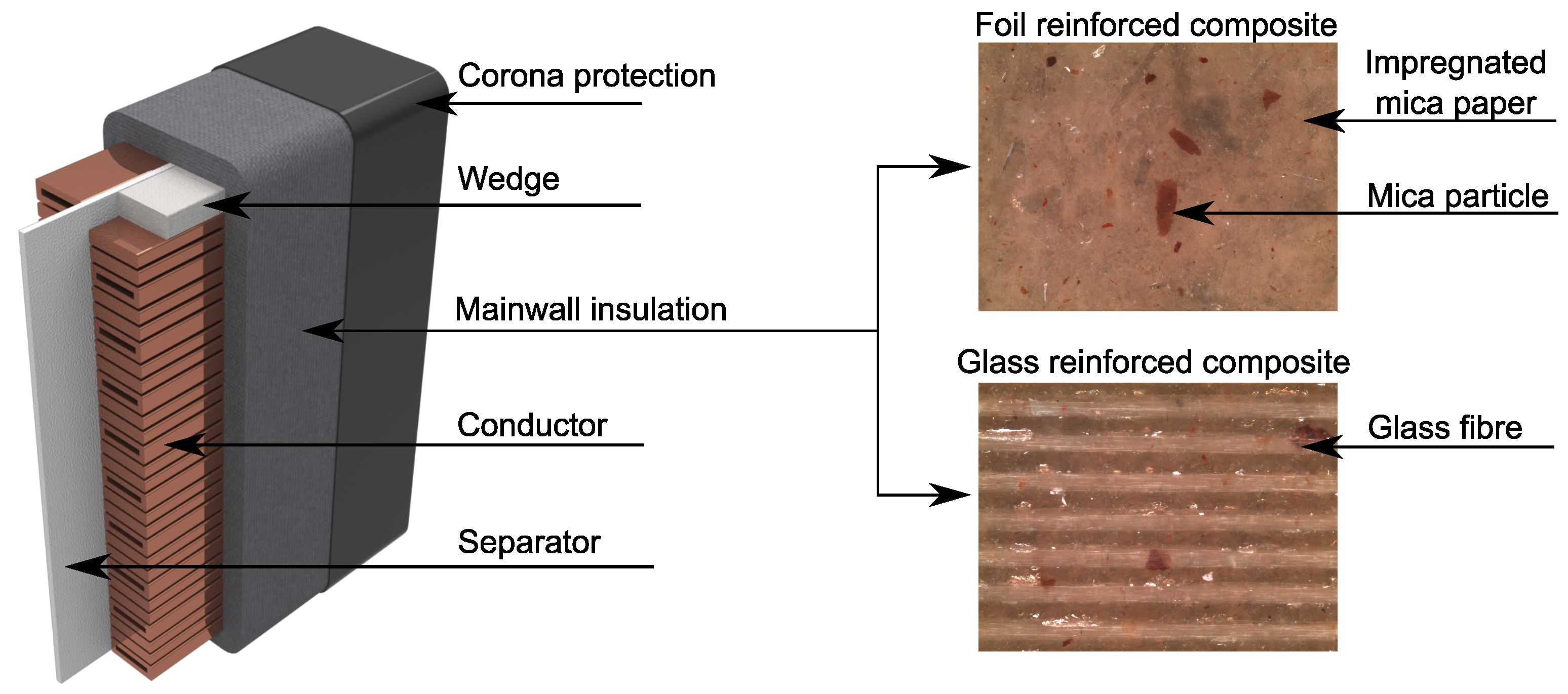
Figure 1. Illustration of stator winding with different structures of mainwall insulation.
Applsci 09 02926 g001
Figure 2. Different fillers used in matrices (a) dispersed particles; (b) exfoliated layered nanosilicates; (c) nonwoven nanofibres.
Applsci 09 02926 g002
Figure 3. Classifications of composite materials depending on the filler size (redrawn and adapted from: [16,27]).
Applsci 09 02926 g003
Figure 4. Structural formula of bisphenol-A diglycidyl ether.
Applsci 09 02926 g004
Figure 5. Analysis of dielectric parameters of Epoxy/MgO composites (adapted from: [32]).
Applsci 09 02926 g005
Figure 6. Changes of dielectric parameters of Epoxy/MgO and Epoxy/MgO+GLYMO composites (adapted from: [32,35]).
Applsci 09 02926 g006
Figure 7. Block diagram of composite preparation.
Applsci 09 02926 g007
Figure 8. X-ray diffraction patterns depending on the different component addition.
Applsci 09 02926 g008
Figure 9. X-ray diffraction patterns of mica composites.
Applsci 09 02926 g009
Figure 10. Resorption current analyses (a) measurement circuit; (b) are over the curve determination by trapezoid integration; (c) time constant determination by tangent curve.
Applsci 09 02926 g010
Figure 11. Partial discharges measurement circuit according to IEC 60270 Std.
Applsci 09 02926 g011
Figure 12. Normal probability plots of investigated parameters of nanostructured micaless microcomposite.
Applsci 09 02926 g012
Figure 13. Real and imaginary parts of complex permittivity of investigated composites.
Applsci 09 02926 g013
Figure 14. Selected PRPD diagrams for investigated composites on 18.5 kV/mm level.
Applsci 09 02926 g014
Table 1. Test conditions for electrical measurements.
ParameterTest Voltage (V)Frequency (Hz)Temperature (°C)
Dielectric strength↑ 3 kV/s50 (AC)
Dissipation factor100050 (AC)23 ± 2
Volume resistivity1000DC
Table 2. Minimum/maximum values of key dielectric parameters of investigated composites.
Samplemin E p (kV/mm)max tan δ (-)min ρ v ( Ω · m)
A—Nanostructured micaless microcomposite53.20.004524.84 × 1014
B—PET reinforced mica composite [28]500.0151 × 10¹³
C—Glass reinforced mica composite [28]350.0151 × 10¹³
Table 3. Parameters determined from resorption current.
SampleArea over Curve (-)Time Constant (s)
A—Nanostructured micaless microcomposite2.08 × 10−85.8
B—PET reinforced mica composite5.89 × 10−87.2
C—Glass reinforced mica composite9.32 × 10−88.8
Table 4. Charge Qiec and PDs inception levels for investigated composites.
SamplePD Inception
(kV/mm)
Charge Qiec 1
(pC)
Charge Qiec 2
(pC)
A—Nanostructured micaless microcomposite18.51010
B—PET reinforced composite16.62037
C—Glass reinforced composite1025117
1 during PDs inception; 2 on 18.5 kV/mm.