Article

Design and Experiment of a Moving Magnet Actuator Based Jetting Dispenser

Department of Mechanical Engineering, National Cheng Kung University (NCKU), Tainan 701, Taiwan
*
Author to whom correspondence should be addressed.
Appl. Sci. 2019, 9(14), 2911; https://doi.org/10.3390/app9142911
Submission received: 12 June 2019 / Revised: 17 July 2019 / Accepted: 18 July 2019 / Published: 20 July 2019
(This article belongs to the Section Mechanical Engineering)

Abstract

:
Developing actuators to drive high-frequency jetting dispensers in the dispensing technology for electronic assembly applications has become a concern in recent years. This study proposed a new jetting dispenser without a displacement amplification mechanism directly actuated by a moving magnet actuator (MMA) to jet small fluid droplets. In this article, the main geometric dimensions of the dispensing cluster including the needle, chamber, and seat-nozzle follow those of previous studies and existing dispensers to reduce design time. The necessary root-mean-square force applied to the dispenser needle, which is the key value for the MMA design, is calculated in detail. An ANSYS Maxwell finite element analysis (FEA) is used to simulate the MMA thrust force and modify geometric dimensions. The droplet size produced by the proposed dispenser is empirically investigated under various backpressure, operating frequency, needle displacement, and fluid temperature conditions. The experimental results indicated that the jet dispenser driven by the moving magnet actuator stably operated at the maximal operating frequency of 80 Hz. Some errors, such as losing droplets and generating small satellite dots around the main dots, did not occur during the operating process. In addition, the size of the proposal dispenser without the displacement-magnifying mechanism was also significantly reduced. To conclude, the jetting dispenser driven by the proposal moving magnet actuator can operate well at a medium frequency and shows great potential for dispensing technologies.

1. Introduction

Dispensing technology has been attracting significant attention due to its potential applications in electronics assembly [1], optoelectronics and LED [2,3], semiconductor packaging [4], and automotive assembly [5,6]. Dispensing technology can be used to transfer fluid materials to the desired positions accurately and rapidly when fluid materials include conductive epoxies, encapsulants, adhesives, and hydrogels [7,8,9]. There are two main approaches in dispensing technology: Contact and non-contact dispensing. Non-contact/jetting dispensing has several advantages and has been used for investigations and applications [10,11,12,13,14,15,16].
The jetting process for non-contact dispensing goes through four stages, as indicated in Figure 1. At the closing stage (Figure 1a), the ball-needle and nozzle-seat touch each other, and the nozzle orifice is closed. In the rising and opening stages (Figure 1b), the needle moves upward, and the pressurized adhesive flows from a syringe into the chamber and fills up the void generated by the nozzle-seat and ball-needle. At the end of the upward travel, the needle stops at this position for a period of time to ensure the filling process is completed. Then, the needle moves downward to punch the nozzle-seat in the dispensing stage (Figure 1c). The acceleration force breaks the adhesive stream. As a result, the extremely high local pressure at the area of nozzle-seat jets the adhesive out of the orifice, and then the adhesive falls down the substrate from 1–3.5 mm to form adhesive droplets. The micro-dot shape is not affected by the shape of the needle tip and substrate surface tension because the dispenser’s needle tip is not in contact with the substrate [17,18].
Currently, three types of actuators used to drive the dispenser needle have been studied. They consist of a piezo-stack actuator (PSA), a magnetostrictive-stack actuator (MSA), and an electro-pneumatic actuator (EPA). Detailed schematic diagrams of these actuators are shown in Figure 2a–d. The PSA is made of a multilayer of reformed Lead–Zirconate–Titanate (PZT) ceramics. The PZT materials generate a mechanical strain when oriented electrical charges are applied. The PSA’s features include a large generated force and fast response; however, the mechanical strain is less than 100 µm at a high excitation voltage of about 200 Volts. The deformation in this PSA is not great enough to directly actuate the needle displacement. Thus, an amplification mechanism including a hinge and lever is used to magnify the displacement to at least 0.35 mm [19,20]. The PSA has two major designs, in which one or two PSA blocks combined with the amplification mechanism and return spring are used, as indicated in Figure 2a,b. The MSA is made of a magneto-active material including many thin Terfenol-D plates, which generates a mechanical strain when exposed to an external magnetic field. Similar to the PSA, the elongation of the MSA is also limited by the small travel range. Thus, mechanical amplification is also used to amplify the needle displacement, as indicated in Figure 2c [11,19]. The size and cost of the PSA and MSA types also increase significantly when utilizing mechanical amplification, so they are more suitable for high-frequency applications. The EPA type uses a fast 3/2 solenoid pneumatic valve to close and open the pressured air provided by an air compressor (Figure 2d). The compressed air travels into the under cylinder chamber and pushes the piston-needle up. In the dispensing stages, the spring’s compression force pushes the piston-needle down to jet the fluid out of the orifice [21,22,23]. The EPA has one electromagnetic valve accompanying the piston-cylinder, which raises the size of the EPA and the operating cost significantly. In addition, the pneumatic system usually incurs a pressure loss during the working process, so the pneumatic actuators have low efficiency compared with other electric-mechanical actuators. The operating frequency of the EPA is also lower than that of the PSA and the MSA types. It is suitable to work at low and medium frequencies.
In this research, the new jet dispenser driven by a moving magnet actuator, which is well known as a type of the voice coil actuator, working at a medium frequency is proposed. Figure 2e shows the MMA diagram, which consists of a permanent magnetic core, a ferrous steel shell, and a winding coil assembly. The electromechanical energy conversion of the MMA is based on the Lorentz force principle. The interaction between the electromagnetic fields of the electric coil and the permanent magnet generates the force to actuate the dispenser needle. The travel length of the MMA shaft is greater than that of the PSA and MSA. The MMA can directly drive the dispenser needle without the displacement-magnifying mechanism, thereby reducing the device size significantly. The operating stability of the EPA is lower than that of the MMA because the EPA depends on the electromagnetic valve and compressed air impact. In addition, the MMA’s core can move in two directions by reversing the current direction. Thus, the MMA dispenser has also been investigated when operating with and without a return spring. The problem of actuators the MSA, EPA, and MMA is the heat generation of the coil, which affects the working efficiency of the dispenser and the droplet size. To maintain the fluid temperature between 40 and 45 °C, an electric fan is attached to the dispenser holder to create heat convection into the environment. The MMA dispenser can generate micro-droplets at a frequency of less than 80 Hz without the displacement-magnifying mechanism. The droplet shape meets the requirement because droplet losses and satellite dots do not occur. In this paper, the MMA dispenser configuration is introduced, in which the main geometric dimensions of the dispensing parts refer to previous research and commercial dispensers. The root-mean-square force (FRMS) calculated in detail is the key input value for the MMA design. In the MMA design, the driving/thrust force generated by the MMA must be larger than the FRMS. Then, a control model creating a voltage pulse to apply in the MMA dispenser is presented. Glycerin is used as the fluid material in the experimental process. The droplet size is examined under the specific backpressure conditions, needle stroke lengths, operation frequencies, and fluid temperatures to evaluate the operation of the MMA dispenser.

2. Configuration of the MMA Dispenser

The configuration of the MMA dispenser including the MMA part and dispensing parts is shown in Figure 3. The MMA includes an annular-shaped permanent magnet (11) made of strong Neodymium ND-48H placed between two iron-ring poles (10). The magnetic field of the permanent magnet is axially oriented. Two identically serial coils (12) are wrapped around the bobbin (16). The bobbin is made of aluminum alloy AL6061 because AL6061 has high thermal conductivity and obtains low effective inductance from the electric coils. The ferromagnetic shell (13) and iron-ring poles (10) are made of carbon steel 1020C, both of which have high permeability and magnetic saturation density 1.6 T to avoid losing the magnetic field [24]. The magnets and iron-ring poles are mounted on a non-ferromagnetic core (7) made of AL6061, and this core is connected to the ball-needle (5) with a connector nut. The stroke-adjusting nut (15) with a thread pitch of 1 mm adjusts the ball-needle displacement from 0 to 2.5 mm. For the dispensing parts, the fluid (17) in the syringe (1) is pressurized with air (18) to form a steady continuous flow. The fluid passes through the fluid connector (2) to the chamber (4) inside the fluid body (6). When the voltage pulse (14) is applied, a current is available. A magnetic field is generated and strongly concentrated at the coil center. This electromagnetic field interacts with the permanent magnetic field to produce the Lorentz force. The Lorentz force drives the core moving upward. The return spring (8) pushes the needle downward in the dispensing stroke. The force direction depends on the direction of the current direction. As a result, the ball-needle, which is made of stainless steel, moves upward or downward to open or close the nozzle orifice (3).

3. MMA Dispenser Design

3.1. Dispensing Parts

To reduce the design time, main geometric dimensions of the dispensing cluster including the ball-needle, chamber, and seat-nozzle follow previous studies and existing dispensers [11,20,25,26]. Figure 4a shows the dimension symbols for the dispensing cluster. Important dimensions can be listed, such as the ball-needle diameter (dne = 2), diameter of nozzle-orifice (Nno = 0.5), length of the nozzle-orifice (Lno = 3), diameter of the nozzle chamber (Dnc = 3), length of the nozzle chamber (lnc = 5.4), chamber diameter (Dc = 4), chamber length (lc = 9.5), inner diameter of fluid connector (Dlc = 2), and diameter of the needle piston (dnp = 3). Other dimensions are chosen for convenience for assembly between the dispensing cluster with the MMA and the dispenser holder. The ball-needle and nozzle are made of stainless steel 304, and AL6061 is the main material used to fabricate the other components.

3.2. Calculation of Driving Force

The driving/thrust force (Fth) generated from the MMA must be larger than the root-mean-square force (FRMS). The FRMS is calculated based on the peak force (FPe), including the resistance force of the glue (FG), friction force of the O-ring (FF), acceleration force of the mass (FM), and the spring force (FSp) as:
FPe = FG + FF + FM + FSp.
The resistance force of the glue (FG) including the damping force (FD) and the upward force in the nozzle seat area (FP) when the needle moves downward, is expressed by:
F G = F D + F P .
The damping force can be calculated by [27]:
F D = v n · C d = v n 2 π μ d ne ( l nc D nc d ne + l c D c d ne ) ,
where vn is the maximum speed of the needle (320 mm/s), Cd is the damping coefficient, and μ is the dynamic viscosity at room temperature (1.49 kg/m s). Dnc, Dc, and dne are the diameters of the nozzle chamber, chamber, and the needle, respectively. lnc and lc are the lengths of the nozzle chamber and chamber, respectively.
The upward force in the nozzle-seat area can be calculated by [11]:
F P = P s · A en + P A A c ,
where PS is the glue pressure between the nozzle-seat and the needle tip. (Aen = 6.38 mm2) is the effective area at the needle end that is directly affected by the PS. PA is the glue pressure in the chamber. AC = 4.71 mm2 is the needle-cap area. In the chamber, the glue pressure PA is determined using the Bernoulli equation [28]:
P A = P sy + ρ g ( h sy h ch ) + 1 2 ρ ( v sy 2 v ch 2 ) ,
where P sy is the maximum backpressure in the syringe (0.5 Bar); h sy = 100   mm and h ch = 16   mm are the glue height in the syringe and chamber, respectively; ρ is the Glycerin density (1261.3 kg/m3), and v gs = 0.1   mm / s and v ch = 1.06   mm / s are the glue speed at the syringe and chamber, respectively. The dot volume is assumed to be 0.5 mm3.
The glue pressure between the needle tip and nozzle seat PS is given by [20,29]:
P S = P A + Δ P ce , b + Δ P ns , b ,
Δ P ce , b = 1 2 ρ C c ξ B Q B 2 A Con 2 = 1 2 ρ C c ( 1 2 ( 1 A Con A en ) 3 / 4 + ( 1 A Con A an ) 2 ) Q B 2 A Con 2 ,
Δ P ns , b = [ ( 3 n + 1 ) Q B + ( 3 n + 1 ) π r S 2 3 n 1 [ ( 3 n + 1 ) ( 1 σ 2 ) 2 n ( 1 σ 2 1 / n 1 σ 1 1 / n ] | v C | n π r S 3 [ ( 1 λ 2 ) 1 + 1 / n σ 1 + 1 / n ( λ 2 σ 2 ) 1 + 1 / n ] ] n 2 l s K r s ,
A Con = 2 π r con ( z m z n ) c o s φ ,
Q B = Q N Q Noz ,
Q N = A en · v n ,
Q Noz = n + 1 3 n 1 π ( d ne 2 ) 2 a ( t ) ,
where ΔPce,b is the drop in pressure because of the expansion and contraction of the flow at the needle tip. ΔPce,b is the backflow pressure drop due to the fluid passing through the annular channel between the ball-seat and the needle in the dispensing stage. ξB is the local loss factor due to the contraction and expansion of the backflow. Cc = 0.64 is the contraction coefficient at the contraction section depending on the ratio of the cross-section area of the nozzle chamber and nozzle seat. QB is the backflow rate in the chamber. A Con is the contraction area of the nozzle chamber depending on the existing position of the needle tip. A AN = 2.19   mm 2 is the cross-section area limited by the ball-seat and needle tip in the annular duct. r con is the contraction-section radius at the existing needle-position. z m = 2.5   mm is the maximum distance from the ball-seat to the needle tip. z n are the needle displacement at the considered position. φ is the inclined angle of the ball-seat. l s   = 1.25 mm is the ball-seat length. r s = 1.24   mm is the ball-seat radius. r n = 1 mm is the needle radius. n = 0.5 is the flow behavior index [29]. σ = 0.81 is the needle’s dimensionless radius σ = r n / r s . λ = 0.72 is the function of σ and n. K = 0.365 Pa.sn is the consistency index. QN is the flow rate created by the downward motion of the needle. QNoz is the flow rate through the needle. a(t) is the flow velocity at the nozzle center. The reference value of a(t) is 4 m/s.
The friction force between the O-ring and the needle (FF) can be calculated by [30]:
F F = 2 π d np r or E or ( 1 D g d np 4 r or ) 1 ( D g d np ) 2 16 r or 2 ,
where Dg = 6 mm and dnp = 3 mm are the cylinder and needle-piston diameters, respectively. ror = 0.8 mm is the cross-section radius of O-ring, and Eor = 4 N/m2 is the elastic modulus of the nitrile rubber material. In Equation (13), the precondition is that the value of Dg–dnp must be less than these of 4ror so that it is not a complex expression.
The acceleration force of load (FM) occurs at the beginning of the filling and dispensing processes and is calculated by equation F M = m L · a , in which, m L is the mass total of the needle (mn), connector nut (mnu), MMA core (ms), permanent magnets (mpm), and ferromagnetic discs (mfd). a is the acceleration a = d v n / d t . The spring force is calculated using Hooke’s law F sp = k · z c . k is the spring stiffness k = 2 N/mm.
The RMS force is expressed by the equation as below [31]:
F RMS = F P e 2 t 1 + ( F G + F F + F S p ) 2 t 2 + ( F M + F S p F G F F ) 2 t 3 t 1 + t 2 + t 3 + t 4 ,
F Pe = F G + F F + F M + F Sp ,
where t1, t2, t3, and t4 are the acceleration time, run time, deceleration time, and dwell time, respectively.
The results obtained from the theoretical calculation of the dispensing cluster include the damping force (FD = 57 × 10−3 N), upward force (FP = 0.81 N), resistance force of the glue (FG = 0.867 N), friction force of the O-ring (FF = 1.84 N), acceleration force of the mass (FM = 6.15 N), and spring force (FSp = 5 N), peak force (FPe = 13.65 N), and the root-mean-square force (FRMS = 8.08 N).

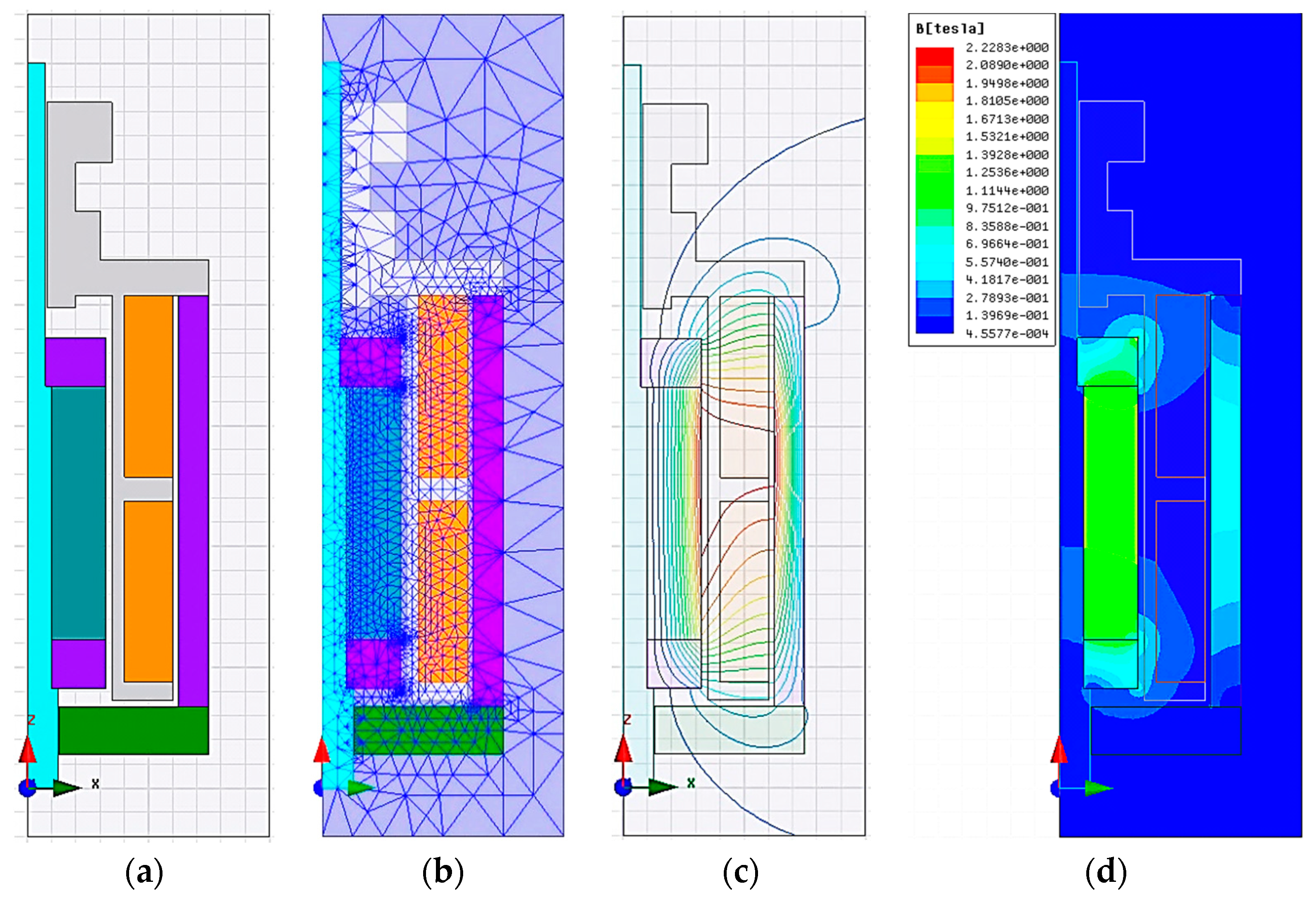
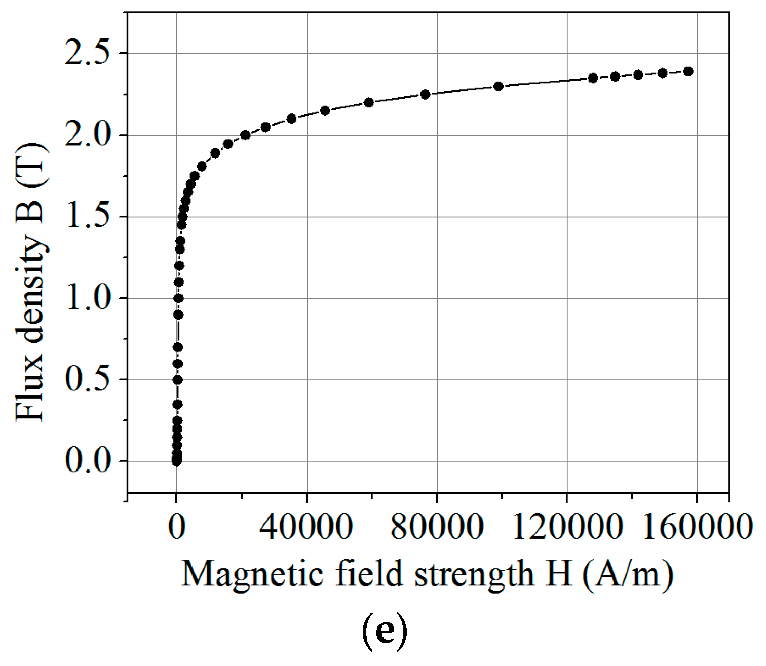
3.3. The MMA Simulation
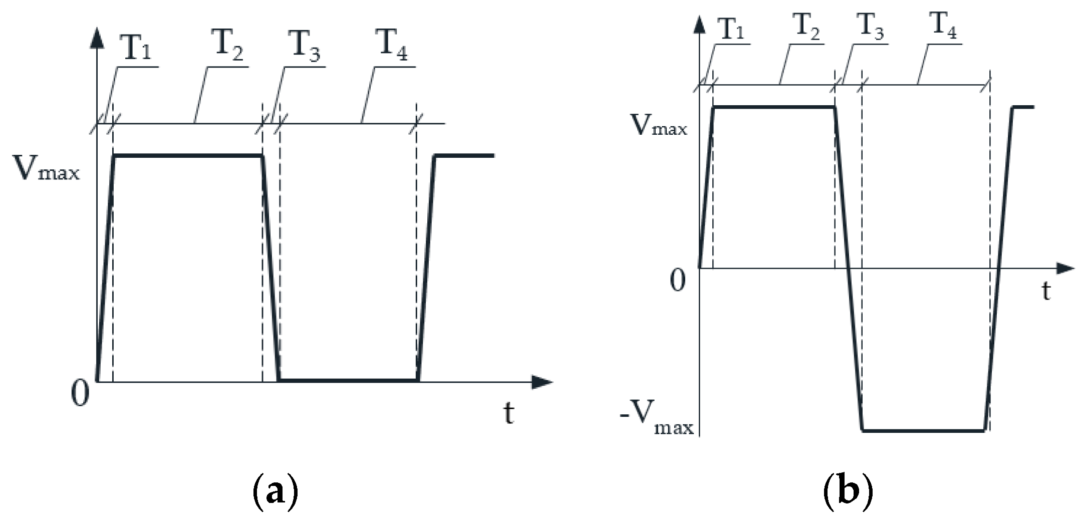
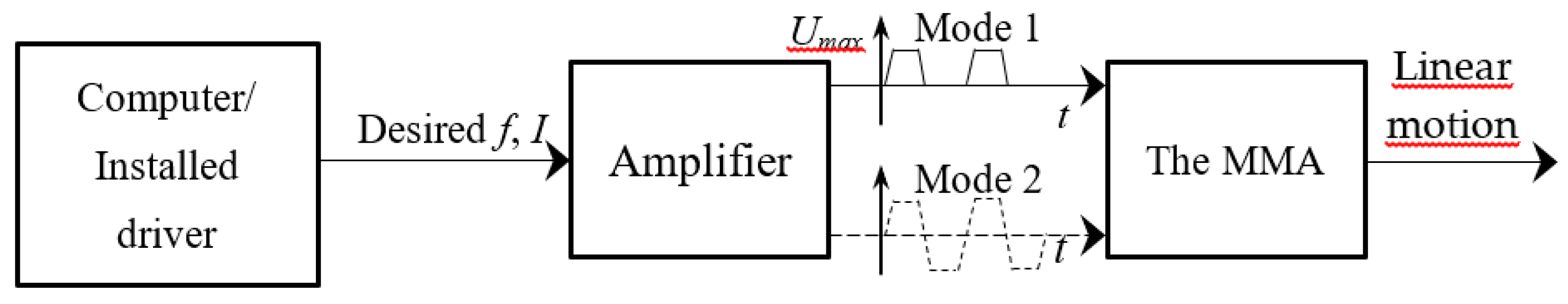
Since the cross-section of the MMA is constant, a 2D axisymmetric model can be used. The thrust force on the moving core, including the shaft, two ferromagnetic discs, and the permanent magnet, is predicted via a 2D magnetostatic solution type in an ANSYS Maxwell simulation. The MMA geometric dimensions are also determined through the process of modifying the MMA model to get the most suitable result. Figure 5a–d show a 2D axisymmetric model of the MMA in Maxwell simulation. In this simulation model, the permanent magnet material is NdFeB-N-48, which has the relative permeability of µ = 1.05, the magnetic retentivity of Br = 1.4 T, and magnetic coercivity of Hc = −1061032.95 A/m. The two iron-ring poles and ferromagnetic shell are made of carbon steel 1020C with a nonlinear B-H curve indicated in Figure 5e [32]. The bobbin, core/shaft, and adjusting nut are made of AL6061. The wire diameter is 0.32 mm, and the number of turns N is 439 turns for each winding coil. The max voltage ranges from 22 to 24 V, and the current applied to the coil ranges from 1.6 to 2.4 A. The simulation results show that the computed thrust force is 9.72, 10.89, 12.12, 13.3, and 14.47 N corresponding to an applied current of 1.6, 1.8, 2.0, 2.2, and 2.4 A, respectively.
The results for the simulated MMA dimensions are listed in Table 1. To confirm that the simulation model is the most approximate description of the actual model, the real MMA model based on the simulated MMA dimensions is fabricated. Figure 6a shows a measuring system designed to measure the thrust force of experimental MMA. The experimental results show that the thrust force is 9.66, 10.47, 11.35, 12.13, and 12.93 N corresponding to an applied current of 1.6, 1.8, 2.0, 2.2, and 2.4 A, respectively. The simulation results are compared with the experimental values with an average error of 5.96%, and shown as Figure 6b. To successfully actuate the dispenser needle, the thrust force Fth generated from the MMA must be greater than the FRMS force. If the safety factor n is 1.3, Fth must take a value greater than 10.5 N. Compared to the experimental results; the current value applied for the MMA must be greater than or equal to 2 A.

3.4. Control Signal

The ball-needle movement is only controllable on half of the displacement cycle that typically is the upward stroke. In the downward stroke, the elastic potential energy coming from the compressed spring’s deformation will convert into kinetic energy and push the needle downward. The single pulse applies for the MMA coil, as shown in Figure 7a. In the closing stage, the voltage has a value of 0 V. In the filling stage, the voltage value rises from 0 to Vmax in time T1; the MMA thrust force drives the needle upward. Then, the Vmax stays in the delay time T2 to keep the needle at the top of the opening stage. When the voltage value drops from Vmax to 0 V, the current is off, and the thrust force is lost. The spring force pushes the needle down to carry out the falling stage T3 and dispensing stage T4. If the return spring is not used for the MMA, the double pulse will be applied for the coil as shown in Figure 7b. In the falling stage T3, the voltage value decreases from Vmax to its negative value –Vmax and the current direction reverses. The Lorentz force direction is reversed to push the needle downward. Then, the −Vmax delays in T4 to keep the needle at the bottom in the closing stage until the new jetting process begins. The double pulse is more active when the response times can be controlled by changing the pulse width. However, the double pulse model consumes twice as much energy as the single pulse model.
Figure 8 shows an open loop operation controlling the MMA. An amplifier driver is installed to communicate with the computer. The desired input frequency f and current I are set on the software interface to send to the amplifier. The current oscillates under the output pulse width modulation (PWM) signal at the desired frequency. The output voltage from the amplifier can be applied under two single pulse and double pulse modes. The single signal/mode 1 controls the dispenser having the return spring, while the double signal/mode 2 controls the dispenser without using the return spring. The two signal forms depend on the connection between the amplifier output gates and the MMA. The MMA generates the thrust force necessary to drive a linear motion of the dispenser needle.

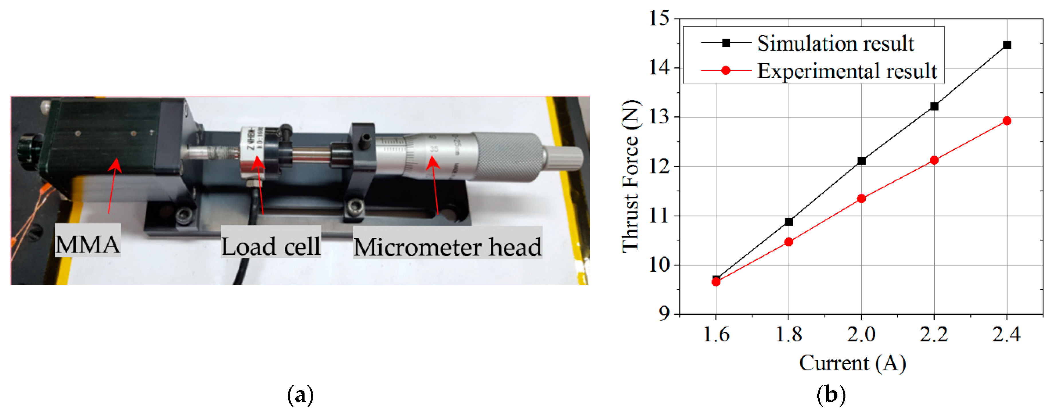
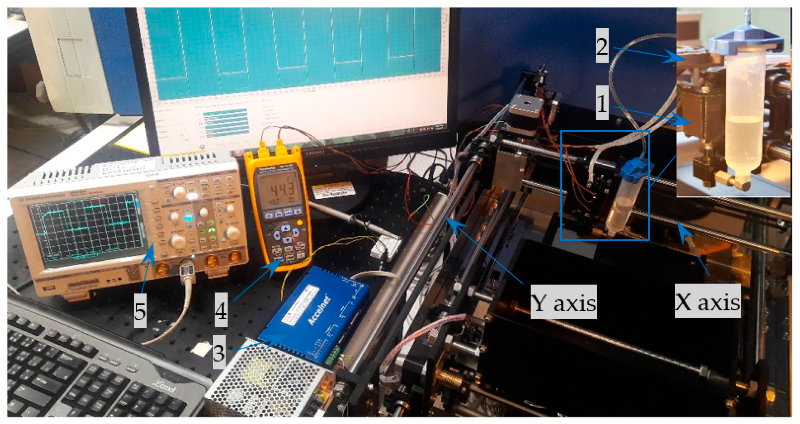
4. Experimental Set-Up

A fully experimental system was set up as illustrated in Figure 9. The MMA dispenser (1) was attached to the 2D jetting system. An accelnet Panel ADP-090-09 amplifier (3) from Copley Controls Corporation generated a square voltage pulse. The Accelnet amplifier was similar to a high-frequency switch. CME 2™ software was used to communicate between the amplifier and the computer via a CANopen network or an RS-232 serial port. The output voltage and current value provided by the Accelnet amplifier were measured on the Scope tool of the CME 2™ software interface. The oscilloscope HMO1024 (5) was used to double-check the output signal from the amplifier.
It should be noted that the MMA generates heat during the period when there is a current in the coil. Under this thermal conduction, the MMA heat transfers to the housing and fluid body. As a result, the droplet diameter was affected when the adhesive inside the fluid body was heated. To reduce the heat, one 12 V, 0.23 A, 2500 rpm DC fan (2) is attached onto the top of the MMA dispenser holder. The airflow from the fan caused the heat to disperse into the environment. The fluid body always stays at a temperature ranging from approximately 40–45 °C. The fluid temperature is checked at point A located on the outside of the fluid body surface, as shown in Figure 4. The TM-747DU thermometer (4) with a resolution of 0.1 °C records the temperature data at the tested point during the operating process.
A glycerin material with physical viscosity of about 950 cP at 20 °C is used in the experiment, which is conducted under the various working conditions, including the pneumatic pressure/backpressure (Psy), ball-needle displacement (zm), operating frequency (F), and fluid temperature (T). Specifically, the changes in droplet diameter under the effects of the former parameters are investigated in detail. The parameters (Psy, zm, F, and T) are set up for four different experiments, as shown in Table 2. Only one of the four parameters is changed while the others remain constant for each experiment.

5. Experimental Results and Discussion
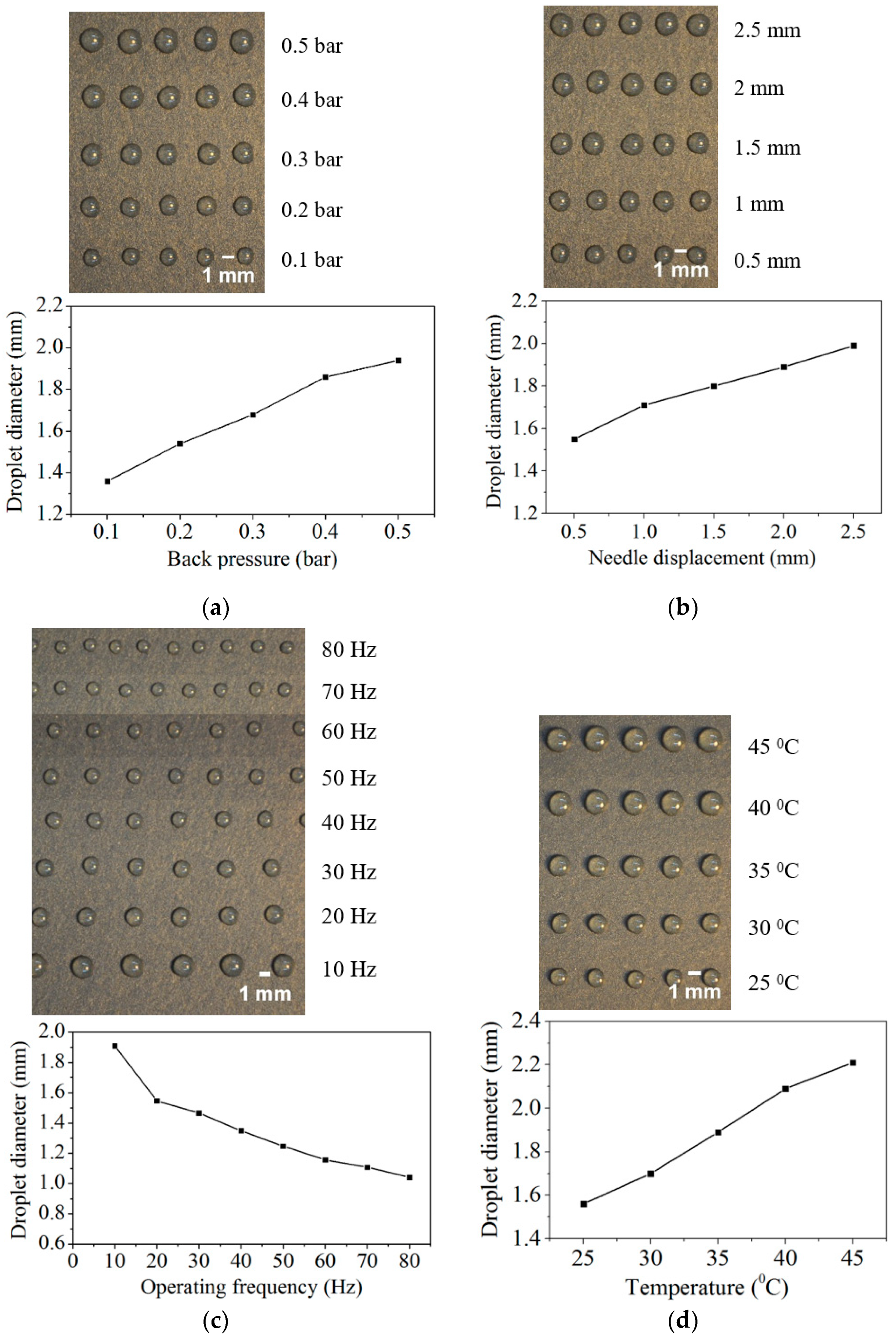
5.1. Backpressure

In the first experiment, the effect of the backpressure on the droplet size is indicated in Figure 10a, in which the droplet diameter steadily increases with increases in the applied backpressure. The average measured diameters of the jetted micro-droplets on the substrate are 1.36, 1.54, 1.68, 1.86, and 1.94 mm at backpressures of 0.1, 0.2, 0.3, 0.4, and 0.5 bar, respectively. When the backpressure is less than 0.1 bar, the high viscous fluid filling speed reduces, and thus the fluid cannot adequately fill the chamber under the high operating frequency.
Furthermore, the low pressure also causes the fluid momentum to be too low to dispense the fluid out of the nozzle. As a result, the fluid accumulates around the outside of the nozzle head, and the surface tension prevents the fluid from falling. When the backpressure is larger than 0.5 bar, the fluid momentum becomes too high; the jetted droplet size is too big, and many small satellite dots are generated around the main dots, which reduces the dispensing quality. Some low viscous fluids, such as water and fuel oil, are jetted without applying backpressure because of the effect of the hydrostatic pressure on the self-filling ability of fluid in the chamber. Depending on the type of materials, a reasonable amount of backpressure should remain during the operating process, which guarantees fluid adequacy in the chamber as well as jetting stability.

5.2. Needle Displacement

In the second experiment, the differences in the droplet diameter are obtained under a variety of needle displacement conditions, as shown in Figure 10b. It can be seen that when the stroke increases, the average droplet diameter increases slightly. The stroke length is adjusted to 0.5, 1, 1.5, 2, and 2.5 mm corresponding to average droplet diameters of 1.55, 1.71, 1.8, 1.89, and 1.99 mm, respectively. When the stroke length is less than 0.5 mm, the fluid momentum is not high enough to jet fluid out of the nozzle orifice, and thus the droplet cannot be formed. As a result, a large volume of fluid accumulates around the nozzle head, which combined with the surface tension, creates resistance and prevents the fluid from falling. However, if the small stroke is less than 0.5 mm, higher backpressure must be applied to obtain higher fluid momentum, and which helps jet the fluid out of the orifice. Based on the requirements for the droplet size, operating frequency, and errors leading to satellite droplets around the main dots, the stroke length must be adjusted accordingly.

5.3. Operating Frequency

The third experiment investigates the effects on the droplet diameter by the operating frequency, as shown in Figure 10c. There are eight injection frequencies of 10, 20, 30, 40, 50, 60, 70, and 80 Hz, corresponding to the pulse widths of 100, 50, 33, 25, 20, 16.67, 14.28, and 12.5 ms, and average droplet diameters of 1.91, 1.55, 1.47, 1.35, 1.25, 1.16, 1.11, and 1.04 mm, respectively. It is clear that the dot size reduces when the working frequency increases. When the dispenser operates under a high frequency, the opening stage time decreases, and the needle stroke is limited. Thus, the gap between the needle top and nozzle-seat decreases. As a result, the fluid volume jetted out of dispenser is reduced, and the droplet size becomes smaller. In this experiment, the maximized achievable operating frequency is 80 Hz at a backpressure of 0.2 bar. If the frequency is over 80 Hz, the fluid cannot adequately fill in the chamber; the jetted fluid is discontinuous and interrupted, and the number of droplets is unsatisfactory. Another defect is small satellite droplets generated around the primary dots.

5.4. Fluid Temperature

The effect of the fluid temperature on the droplet diameter is illustrated in Figure 10d, in which it can be seen that the droplet size increases significantly when the fluid temperature rises. The fluid viscosity varies with increases in the temperature; the surface tension decreases at the high temperature, and the adhesive stream is easily separated into droplets. Thus, the adhesive is dispensed out of the nozzle orifice at a significantly larger volume. The observed average droplet diameters at temperatures of 25, 30, 35, 40, and 45 °C are 1.56, 1.7, 1.89, 2.09, and 2.21 mm, respectively. However, the adhesive performance decreases when the material viscosity drops, and the fluid spreads to form big dots, which reduces the position accuracy of the desired points. The suitable temperature to jet the glycerin is in the range of 35–45 °C.

6. Conclusions

Non-contact dispensing technology exhibits good potential for electronics packaging applications and has attracted researchers in recent years. In this study, the design and experimental validation of a tan MMA-based jet dispenser are presented. The force thrust of the MMA needed to actuate the dispenser needle is determined through theoretical calculations. The dimensions of the MMA are analyzed and evaluated using FEA-based ANSYS Maxwell software. The working frequency of the jetting dispenser is shown to reach a maximum of 80 Hz. The dispenser needle stroke is high enough to finish the jetting process without using a magnifying device. The droplets generated by the MMA jet dispenser also achieve uniformity in shape and size when working under the effects of changed conditions, such as the backpressure, operating frequency, needle displacement, and fluid temperature. The problem of heat generation in the MMA is also solved by attaching a DC fan onto the dispenser holder, so the fluid temperature is managed and ranges from 40–45 °C. Problems such as increasing the operating frequency and reducing the impact of heat on the performance of the MMA will be addressed in future research. From the initial results of this study, the MMA dispenser could be considered a potential actuator type for the jetting dispenser used in electronics and automotive assembly applications.

Author Contributions

Methodology, M.-S.T. and S.-J.H.; investigation, M.-S.T.; formal analysis, M.-S.T.; validation, S.-J.H.; writing—original draft preparation, M.-S.T.; writing—review and editing, M.-S.T. and S.-J.H.; and supervision, S.-J.H.

Funding

This research received no extend funding.

Conflicts of Interest

The authors declare no conflict of interest.

References

  1. Chen, X.B.; Zhang, W.J.; Schoenau, G.; Surgenor, B. Off-line control of time-pressure dispensing processes for electronics packaging. IEEE Trans. Electron. Packag. Manuf. 2003, 26, 286–293. [Google Scholar] [CrossRef]
  2. Chen, K.; Zhang, R.; Lee, S.R. Integration of phosphor printing and encapsulant dispensing processes for wafer level LED array packaging. In Proceedings of the 11th International Conference on Electronic Packaging Technology & High Density Packaging, Xi’an, China, 16–19 August 2010; pp. 1386–1392. [Google Scholar]
  3. Chen, Y.; Wang, F.; Li, H.X. Experimental and modeling study of breakup behavior in silicone jet dispensing for light-emitting diode packaging. IEEE Trans. Compon. Packag. Manuf. Technol. 2015, 5, 1019–1026. [Google Scholar] [CrossRef]
  4. Babiarz, A.J. Advances in jetting small dots of high viscosity fluids for electronic and semiconductor packaging. In Proceedings of the 11th Annual Pan Pacific Microelectronics Symposium, Kauai, HI, US, 17–19 Januar 2006; pp. 243–247. [Google Scholar]
  5. Hicks, C.R.; Carlson, B.E.; Mallick, P. Rheological study of automotive adhesives: Influence of storage time, temperature and shear rate on viscosity at dispensing. Int. J. Adhes. Adhes. 2015, 63, 108–116. [Google Scholar] [CrossRef]
  6. Mortimer, J. Adhesive bonding of car body parts by industrial robot. Ind. Robot. 2004, 31, 423–428. [Google Scholar] [CrossRef]
  7. Liu, S.; Luo, X. LED packaging for lighting applications: Design, manufacturing, and testing, 1st ed.; Wiley: Hoboken, NJ, USA, 2011. [Google Scholar]
  8. Sarvar, F.; Hutt, D.A.; Whalley, D.C. Application of adhesives in MEMS and MOEMS assembly: A review. In Proceedings of the 2nd International IEEE Conference on Polymers and Adhesives in Microelectronics and Photonics on POLYTRONIC, Zalaegerszeg, Hungary, 23–26 June 2002; pp. 22–28. [Google Scholar]
  9. Tekin, T. Review of packaging of optoelectronic, photonic, and MEMS components. IEEE J. Sel. Topics Quantum Electron. 2011, 17, 704–719. [Google Scholar] [CrossRef]
  10. Wang, L.; Du, J.; Luo, Z.; Du, X.; Li, Y.; Sun, D. Design and experiment of a jetting dispenser driven by piezostack actuator. IEEE Trans. Compon. Packag. Manuf. Technol. 2012, 3, 147–156. [Google Scholar] [CrossRef]
  11. Zhou, C.; Li, J.; Duan, J.; Deng, G. The principle and physical models of novel jetting dispenser with giant magnetostrictive and a magnifier. Sci. Rep. 2015, 5, 18294. [Google Scholar] [CrossRef] [PubMed] [Green Version]
  12. Quinones, H.; Babiarz, A.; Fang, L. Jetting technology: A way of the future in dispensing. In Proceedings of the 4th International Symposium on Electronic Materials and Packaging, Kaohsiung, Taiwan, 4–6 December 2002; pp. 7–14. [Google Scholar]
  13. Saidman, L.B.; Taylor, E.C. Force amplifying driver system and jetting dispenser and method of dispensing fluid. U.S. Patent 9,233,388, 12 January 2016. [Google Scholar]
  14. Clark, J.A.; Riney, J.M.; Taylor, E.C. Jetting discrete volumes of high viscosity liquid. U.S. Patent 9,314,812, 19 April 2016. [Google Scholar]
  15. Zhou, C.; Deng, G.; Li, J.; Duan, J. Flow channel influence of a collision-based piezoelectric jetting dispenser on jet performance. Sensors 2018, 18, 1270. [Google Scholar] [CrossRef] [PubMed]
  16. Kim, K.-Y.; Chang, H.; Lee, W.-D.; Cai, Y.-F.; Chen, Y.-J. The Influence of Needle Assembly Sliding of the Jetting Dispenser on the Characteristics of Blood Glucose Test Strip. In Proceedings of the 2018 IEEE International Conference on Advanced Manufacturing (ICAM), Yunlin, Taiwan, 23–25 November 2018; pp. 235–238. [Google Scholar]
  17. Piracci, A.F. Advantages of non-contact dispensing in SMT assembly processes. In Proceedings of the SMTA International Conference, San Jose, CA, USA, 12–16 September 1999. [Google Scholar]
  18. Jianping, L.; Guiling, D. Technology development and basic theory study of fluid dispensing-a review. In Proceedings of the 6th IEEE CPMT Conference on High Density Microsystem Design and Packaging and Component Failure Analysis, Shanghai, China, 3 July 2004; pp. 198–205. [Google Scholar]
  19. John, S.; Sirohi, J.; Wang, G.; Wereley, N.M. Comparison of piezoelectric, magnetostrictive, and electrostrictive hybrid hydraulic actuators. J. Intel. Mat. Syst. Str. 2007, 18, 1035–1048. [Google Scholar] [CrossRef]
  20. Nguyen, Q.H.; Han, Y.-M.; Choi, S.-B.; Hong, S.-M. Dynamic characteristics of a new jetting dispenser driven by piezostack actuator. IEEE Trans. Electron. Packag. Manuf. 2008, 31, 248–259. [Google Scholar] [CrossRef]
  21. Jia, H.; Hua, Z.; Li, M.; Zhang, J.; Zhang, J. A jetting system for chip on glass package. In Proceedings of the International Conference on Electronic Packaging Technology & High Density Packaging, Beijing, China, 10–13 August 2009; pp. 954–960. [Google Scholar]
  22. Nguon, B.; Jouaneh, M. Design and characterization of a precision fluid dispensing valve. Int. J. Adv. Manuf. Tech. 2004, 24, 251–260. [Google Scholar] [CrossRef]
  23. Zhang, J.; Jia, H.; Zhang, J. A fluid dynamic analysis in the chamber and nozzle for a jetting dispenser design. In Proceedings of the 11th International Conference on Electronic Packaging Technology & High Density Packaging, Xi’an, China, 16–19 August 2010; pp. 879–883. [Google Scholar]
  24. Hiemstra, D.B.; Parmar, G.; Awtar, S. Performance tradeoffs posed by moving magnet actuators in flexure-based nanopositioning. IEEE/ASME Trans. Mechatronics. 2014, 19, 201–212. [Google Scholar] [CrossRef]
  25. Jet Dispensers, Nordson-Corporation. Available online: https://www.nordson.com/en/products/jet-dispensers (accessed on 25 September 2018).
  26. Liquidyn Micro Dispensing Valves, Integrated-Dispensing-Systems-Ltd. Available online: http://www.fluidmetering.co.uk/liquidyn/liquidyn_micro_valves.htm (accessed on 26 September 2018).
  27. Lobontiu, N. Mechanical Elements, In System dynamics for engineering students: Concepts and applications, 1st ed.; Academic Press: Cambridge, MA, USA, 2017; pp. 23–75. [Google Scholar]
  28. Hong, Y.P.; Li, H.X. Comparative study of fluid dispensing modeling. IEEE Trans. Electron. Packag. Manuf. 2003, 26, 273–280. [Google Scholar] [CrossRef]
  29. Zhao, Y.X.; Li, H.X.; Ding, H.; Xiong, Y.L. Integrated modelling of a time-pressure fluid dispensing system for electronics manufacturing. Int. J. Adv. Manuf. Tech. 2005, 26, 1–9. [Google Scholar] [CrossRef]
  30. Al-Ghathian, F.; Tarawneh, M. Friction forces in O-ring sealing. Am. J. Appl. Sci. 2005, 2, 626–632. [Google Scholar]
  31. Feng, X.; Duan, Z.; Fu, Y.; Sun, A.; Zhang, D. The technology and application of voice coil actuator. In Proceedings of the Second International Conference on Mechanic Automation and Control Engineering, Hohhot, China, 15–17 July 2011; pp. 892–895. [Google Scholar]
  32. Free BH Curves of low carbon steel—SAE1020. Available online: https://magweb.us/free-bh-curves (accessed on 10 April 2019).
Figure 1. Fluid jetting process. 1. Ball-needle; 2. nozzle-seat; 3. nozzle orifice; 4. substrate; 5. chamber; 6. pressured adhesive; and 7. adhesive dot.
Applsci 09 02911 g001
Figure 2. Schematic diagram of four actuators. (a) Using one piezo-stack and amplification mechanism; (b) using two piezo-stack and amplification mechanism; (c) using a giant magnetostrictive and amplification mechanism; (d) using an electro-pneumatic actuator; and (e) using a linear moving magnet actuator.
Applsci 09 02911 g002
Figure 3. The moving magnet actuator (MMA) dispenser configuration. 1. Syringe; 2. fluid connector; 3. nozzle; 4. chamber; 5. ball-needle; 6. fluid body; 7. shaft; 8. return spring; 9. housing; 10. ferromagnetic disc; 11. permanent magnet; 12. coil; 13. ferromagnetic shell; 14. voltage pulse; 15. stroke adjusting nut; 16. bobbin; 17. fluid; 18. pressurized air; A. temperature checkpoint.
Applsci 09 02911 g003
Figure 4. Configuration of dispensing parts. (a) Dimensional specifications; and (b) dynamic analysis in the dispensing stage.
Applsci 09 02911 g004
Figure 5. The finite element analysis model of the MMA. (a) MMA model; (b) mesh model; (c) flux distribution at excited current of 2.4 A; (d) magnetic flux density at excited current of 2.4 A; (e) B–H curve of 1020 C.
Applsci 09 02911 g005aApplsci 09 02911 g005b
Figure 6. Measuring driving force. (a) Measuring system; (b) comparison of experiment and simulation results.
Applsci 09 02911 g006
Figure 7. Voltage control scheme. (a) Single pulse; and (b) double pulse. T1: Rising stage; T2: Opening stage; T3: Falling stage; T4: Dispensing stage.
Applsci 09 02911 g007
Figure 8. Open loop control.
Applsci 09 02911 g008
Figure 9. Experimental test system. 1. MMA dispenser; 2. direct current (DC) fan; 3. Accelnet amplifier; 4. thermometer; and 5. oscilloscope.
Applsci 09 02911 g009
Figure 10. Experimental results for the droplet diameters. (a) Backpressure effect; (b) needle placement effect; (c) operating frequency effect; and (d) fluid temperature effect.
Applsci 09 02911 g010
Table 1. The main dimensions of the MMA.
DimensionsValue (mm)DimensionsValue (mm)
Core radiusrco = 2Permanent magnet heighthpm = 21
Ferromagnetic-disc thicknesslfd = 4Permanent magnet radiusrpm = 6.5
Needle-piston radiusrnp = 2.5Bobbin inner radiusrib = 7.5
Height of coilhc = 15Bobbin outer radiusrob = 12
Coil thicknessrct = 4Shell inner radiusris = 12.5
Spacing between two coilslsp = 2Shell outer radiusros = 15
Table 2. The setup parameters for the four experiments.
Psy (Bar)zm (mm)F (Hz)T (°C)
Exp. 10.1–0.50.52025
Exp. 20.20.5–2.52025
Exp. 30.20.510–8025
Exp. 40.20.52025–45

