An Improved Optical Flow Algorithm Based on Mask-R-CNN and K-Means for Velocity Calculation

 , ,
, ,  ,
, 
Abstract
1. Introduction
2. Algorithm Design
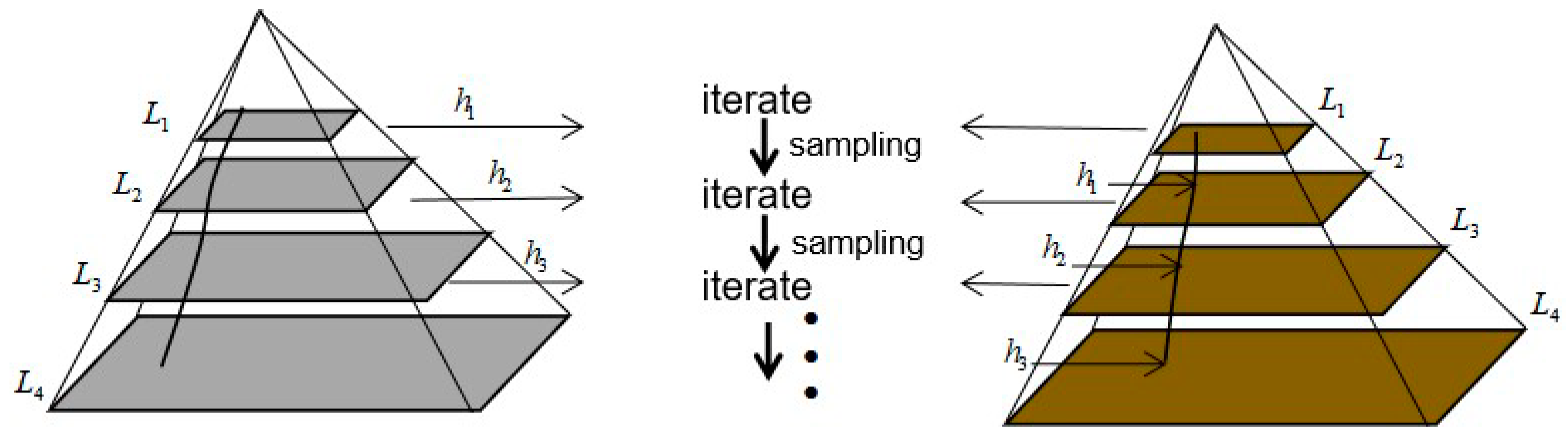
2.1. Pyramid LK Algorithm
2.2. K-Means
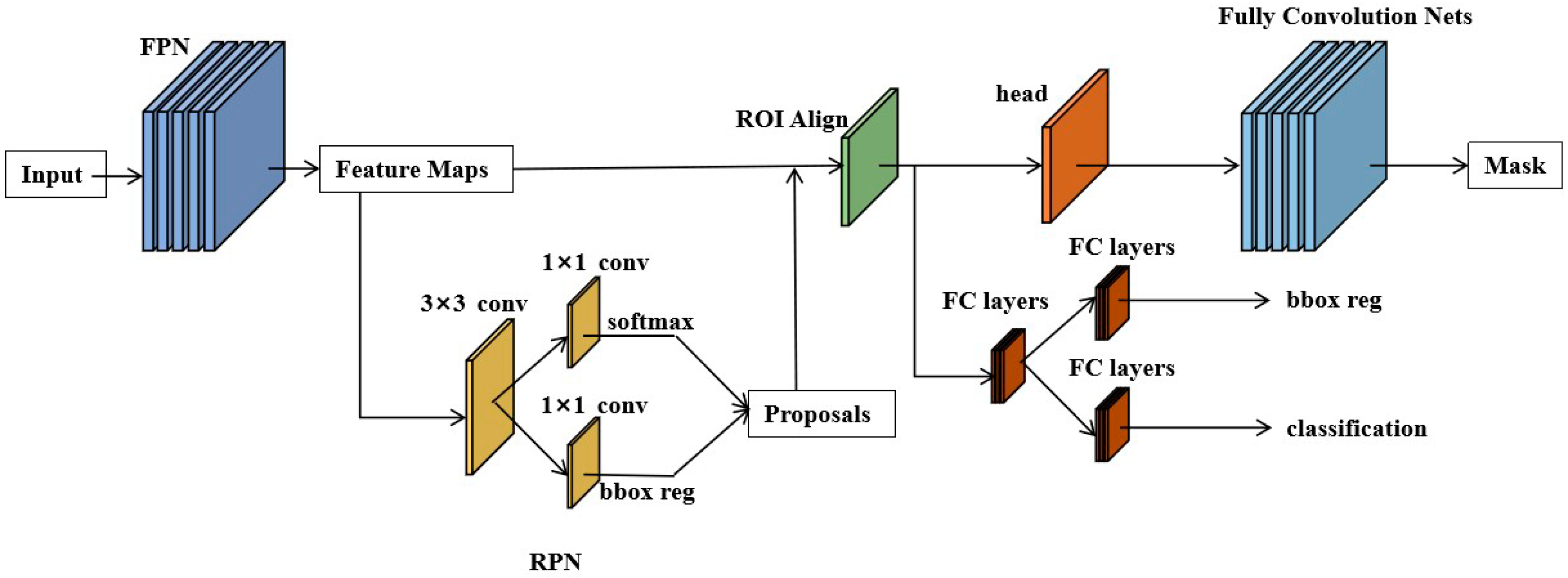
2.3. Mask-R-CNN
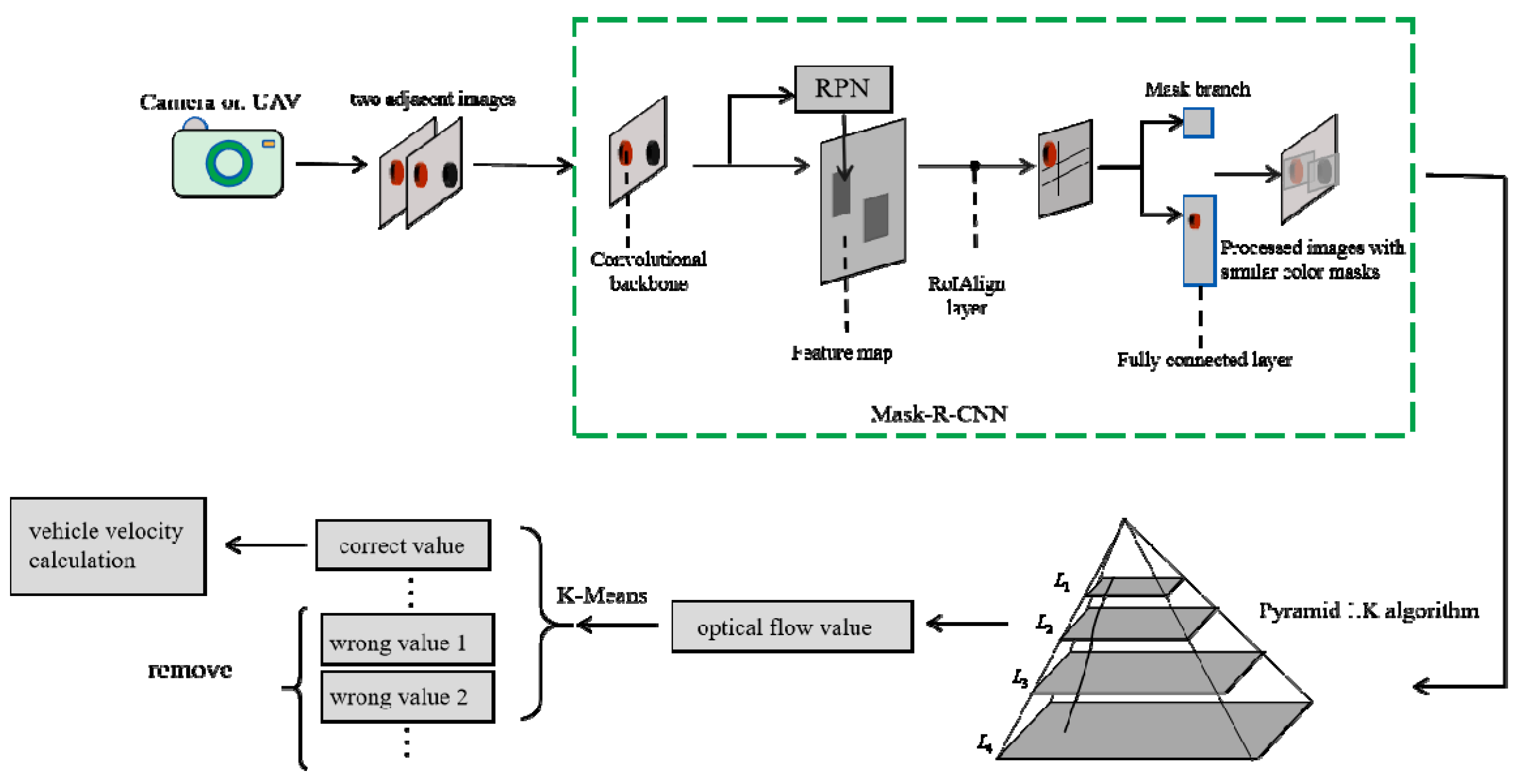
2.4. Pyramid LK Algorithm Based on Mask-R-CNN and K-Means
2.5. Practical Analysis of the Algorithm
3. Experiments and Evaluation
3.1. Experimental Equipment
3.2. The Evaluation of the Improved Optical Flow Algorithm for Velocity Calculation
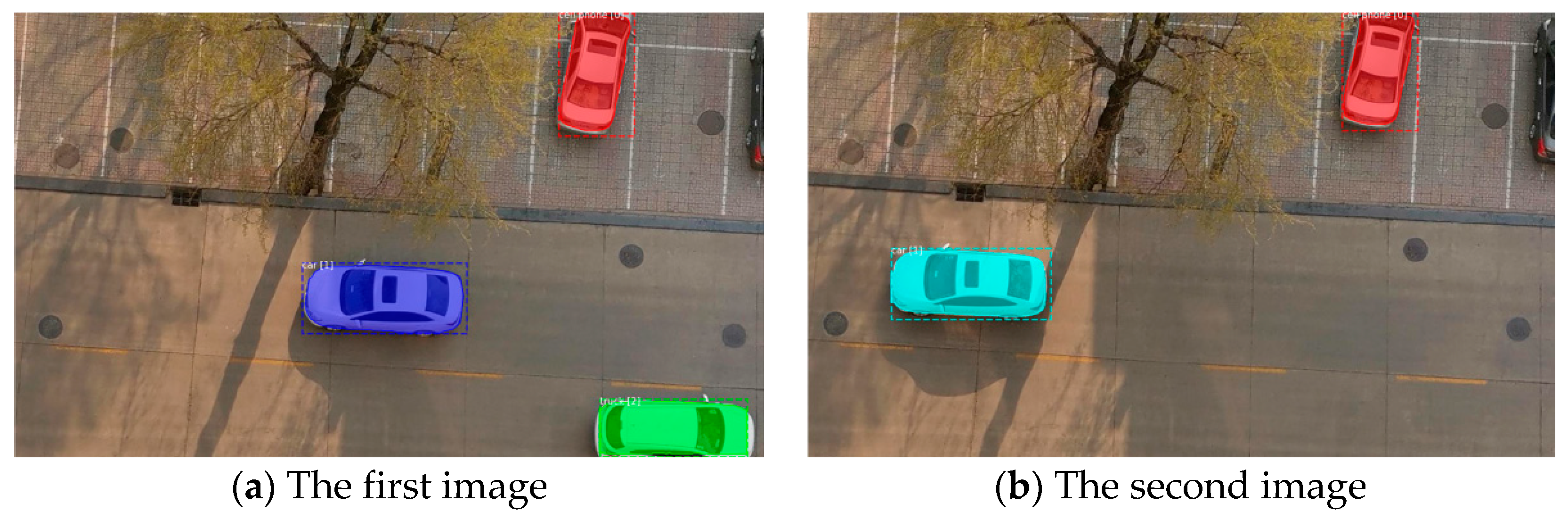
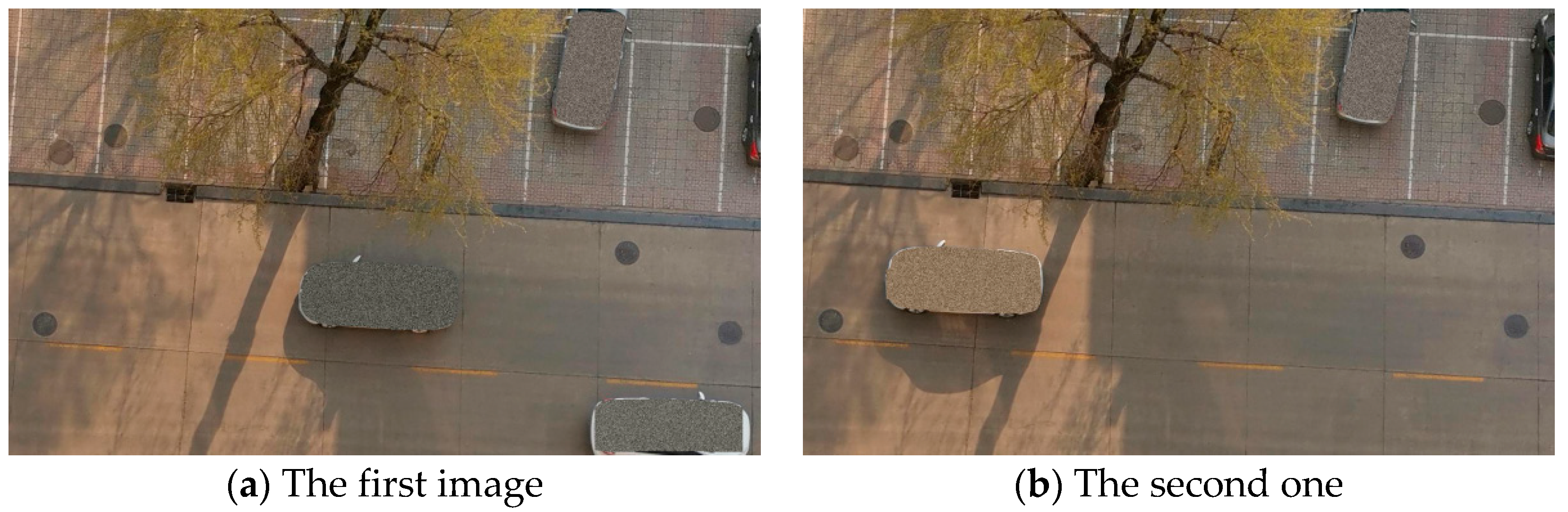
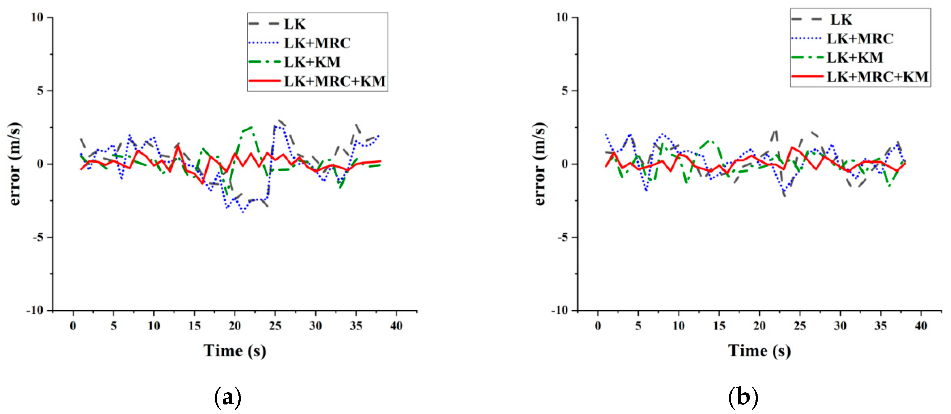
3.2.1. Experiment One in the Normal Application Circumstance
3.2.2. Experiment Two in the Circumstance with Many Moving Objects
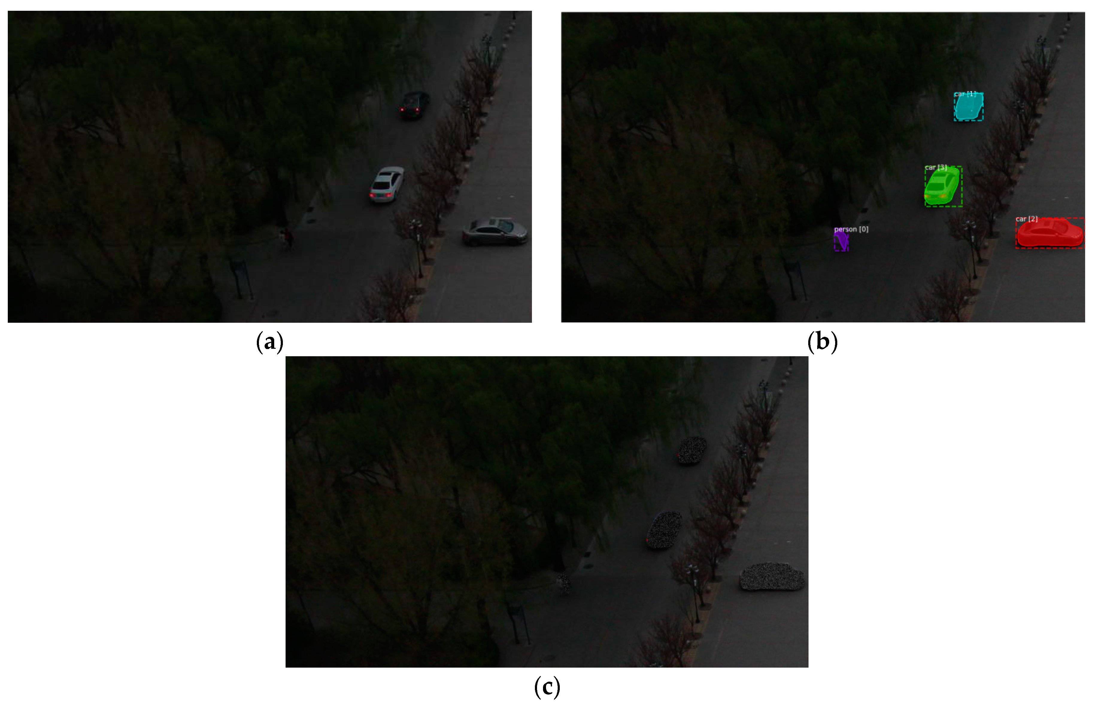
3.2.3. Experiment Three in the Circumstance with Dim Light
4. Conclusions
Author Contributions
Funding
Conflicts of Interest
References
- Guo, X.; Tang, J.; Li, J.; Wang, C.; Shen, C.; Liu, J. Determine turntable coordinate system considering its non-orthogonality. Rev. Sci. Instrum. 2019, 90, 033704. [Google Scholar] [CrossRef] [PubMed]
- Crivelli, T.; Fradet, M.; Conze, P.H.; Robert, P.; Perez, P. Robust Optical Flow Integration. IEEE Trans. Image Process. 2015, 24, 484–498. [Google Scholar] [CrossRef] [PubMed]
- Shen, C.; Yang, J.; Tang, J.; Liu, J.; Cao, H. Note: Parallel processing algorithm of temperature and noise error for micro-electro-mechanical system gyroscope based on variational mode decomposition and augmented nonlinear differentiator. Rev. Sci. Instrum. 2018, 89, 076107. [Google Scholar] [CrossRef] [PubMed]
- Li, P.; Sheng, G.; Zhang, X.; Wu, J.; Xu, B.; Liu, X.; Zhang, Y. Underwater terrain-aided navigation system based on combination matching algorithm. Isa Trans. 2018, 78, 80–87. [Google Scholar] [CrossRef] [PubMed]
- Cao, H.; Zhang, Y.; Shen, C.; Liu, Y.; Wang, X. Temperature Energy Influence Compensation for MEMS Vibration Gyroscope Based on RBF NN-GA-KF Method. Shock Vib. 2018. [Google Scholar] [CrossRef]
- Zhang, C.S.; Elaksher, A. An Unmanned Aerial Vehicle-Based Imaging System for 3D Measurement of Unpaved Road Surface Distresses. Comput. Aided Civ. Infrastruct. Eng. 2012, 27, 118–129. [Google Scholar] [CrossRef]
- Shen, C.; Song, R.; Li, J.; Zhang, X.; Tang, J.; Shi, Y.; Liu, J.; Cao, H. Temperature drift modeling of MEMS gyroscope based on genetic-Elman neural network. Mech. Syst. Signal Process. 2016, 72, 897–905. [Google Scholar]
- Nemra, A.; Aouf, N. Robust INS/GPS Sensor Fusion for UAV Localization Using SDRE Nonlinear Filtering. IEEE Sens. J. 2010, 10, 789–798. [Google Scholar] [CrossRef]
- Seo, S.-H.; Lee, B.-H.; Im, S.-H.; Jee, G.-I. Effect of Spoofing on Unmanned Aerial Vehicle using Counterfeited GPS Signal. J. Position. Navig. Timing 2015, 4, 57–65. [Google Scholar] [CrossRef]
- Shen, C.; Liu, X.; Cao, H.; Zhou, Y.; Liu, J.; Tang, J.; Guo, X.; Huang, H.; Chen, X. Brain-like Navigation Scheme based on MEMS-INS and Place Recognition. Appl. Sci. 2019, 9, 1708. [Google Scholar] [CrossRef]
- Noureldin, A.; El-Shafie, A.; Bayoumi, M. GPS/INS integration utilizing dynamic neural networks for vehicular navigation. Inf. Fusion 2011, 12, 48–57. [Google Scholar] [CrossRef]
- Guo, X.; Tang, J.; Li, J.; Shen, C.; Liu, J. Attitude Measurement based on Imaging Ray Tracking Model and Orthographic Projection with Iteration Algorithm. ISA Trans. 2019. [Google Scholar] [CrossRef] [PubMed]
- Bhatt, D.; Aggarwal, P.; Devabhaktuni, V.; Bhattacharya, P. A novel hybrid fusion algorithm to bridge the period of GPS outages using low-cost INS. Expert Syst. Appl. 2014, 41, 2166–2173. [Google Scholar] [CrossRef]
- Lu, Y.; Xue, Z.; Xia, G.; Zhang, L. A survey on vision-based UAV navigation. Geo-Spat. Inf. Sci. 2018, 21, 21–32. [Google Scholar] [CrossRef]
- Cao, H.; Zhang, Y.; Han, Z.; Shao, X.; Gao, J.; Huang, K.; Shi, Y.; Tang, J.; Shen, C.; Liu, J. Pole-Zero-Temperature Compensation Circuit Design and Experiment for Dual-mass MEMS Gyroscope Bandwidth Expansion. IEEE/ASME Trans. Mechatron. 2019, 24, 677–688. [Google Scholar] [CrossRef]
- Guo, H.; Zhu, Q.; Tang, J.; Nian, F.; Liu, W.; Zhao, R.; Du, F.; Yang, B.; Liu, J. A temperature and humidity synchronization detection method based on microwave coupled-resonator. Sens. Actuators B 2018, 261, 434–440. [Google Scholar] [CrossRef]
- Gibson, J.J. The Perception of the Visual World, 1st ed.; Houghton Mifflin Company: Boston, MA, USA, 1950. [Google Scholar]
- Poggio, T.; Reiehardt, W. Visual control orientation behavior in the fly: Part II. Towards underlying neural interactions. Q. Rev. Biophys. 1976, 9, 377–438. [Google Scholar] [CrossRef] [PubMed]
- Horn, B.; Schunck, B. Determining optical flow. Artif. Intell. 1981, 17, 185–203. [Google Scholar] [CrossRef]
- Tu, Z.; Xie, W.; Zhang, D.; Poppe, R.; Veltkamp, R.C.; Li, B.; Yuan, J. A survey of variational and CNN-based optical flow techniques. Signal Process. Image Commun. 2019, 72, 9–24. [Google Scholar] [CrossRef]
- Baker, S.; Scharstein, D.; Lewis, J.P.; Roth, S.; Black, M.J.; Szeliski, R. A Database and Evaluation Methodology for Optical Flow. Int. J. Comput. Vis. 2011, 92, 1–31. [Google Scholar] [CrossRef]
- Niu, Y.; Xu, Z.W.; Che, X.J. Dynamically Removing False Features in Pyramidal Lucas-Kanade Registration. IEEE Trans. Image Process. 2014, 23, 3535–3544. [Google Scholar] [CrossRef] [PubMed]
- Herisse, B.; Hamel, T.; Mahony, R.; Russotto, F.-X. Landing a VTOL Unmanned Aerial Vehicle on a Moving Platform Using Optical Flow. IEEE Trans. Robot. 2012, 28, 77–89. [Google Scholar] [CrossRef]
- Wang, Z.; He, G.; Du, W.; Zhou, J.; Han, X.; Wang, J.; He, H.; Guo, X.; Wang, J.; Kou, Y. Application of Parameter Optimized Variational Mode Decomposition Method in Fault Diagnosis of Gearbox. IEEE Access 2019, 7, 44871–44882. [Google Scholar] [CrossRef]
- Brox, T.; Malik, J. Large Displacement Optical Flow: Descriptor Matching in Variational Motion Estimation. IEEE Trans. Pattern Anal. Mach. Intell. 2011, 33, 500–513. [Google Scholar] [PubMed]
- Sun, D.; Roth, S.; Black, M.J. A Quantitative Analysis of Current Practices in Optical Flow Estimation and the Principles behind Them. Int. J. Comput. Vis. 2014, 106, 115–137. [Google Scholar] [CrossRef]
- Forster, C.; Pizzoli, M.; Scaramuzza, D. SVO: Fast semi-direct monocular visual odometry. In Proceedings of the 2014 IEEE International Conference on Robotics and Automation (ICRA), Hong Kong, China, 31 May–7 June 2014; pp. 15–22. [Google Scholar]
- Peng, Y.A.; Chen, Z.X.; Wu, Q.M.J.; Liu, C.Y. Traffic flow detection and statistics via improved optical flow and connected region analysis. Signal Image Video Process. 2018, 12, 99–105. [Google Scholar] [CrossRef]
- Varol, G.; Laptev, I.; Schmid, C. Long-Term Temporal Convolutions for Action Recognition. IEEE Trans. Pattern Anal. Mach. Intell. 2018, 40, 1510–1517. [Google Scholar] [CrossRef] [PubMed]
- He, K.; Gkioxari, G.; Dollar, P.; Girshick, R. Mask R-CNN. In Proceedings of the 2007 IEEE Conference on Computer Vision and Pattern Recognition, Minneapolis, MN, USA, 17–22 June 2007. [Google Scholar]
- Wang, Z.; Du, W.; Wang, J. Research and Application of Improved Adaptive MOMEDA Fault Diagnosis Method. Measurement 2019, 140, 63–75. [Google Scholar] [CrossRef]
- Chung, K.-L.; Lin, K.-S. An efficient line symmetry-based K-means algorithm. Pattern Recognit. Lett. 2006, 27, 765–772. [Google Scholar] [CrossRef]
- Ren, S.Q.; He, K.M.; Girshick, R.; Sun, J. Faster R-CNN: Towards Real-Time Object Detection with Region Proposal Networks. IEEE Trans. Pattern Anal. Mach. Intell. 2017, 39, 1137–1149. [Google Scholar] [CrossRef]
- Lu, S.; Ren, C.; Zhang, J.; Zhai, Q.; Liu, W. A Novel Approach to Droplet’s 3D Shape Recovery Based on Mask R-CNN and Improved Lambert(-)Phong Model. Micromachines (Basel) 2018, 9, 462. [Google Scholar] [CrossRef] [PubMed]
- Wang, Z.; Zhou, J.; Wang, J.; Du, W.; Wang, J.; Han, X.; He, G. A novel Fault Diagnosis Method of Gearbox Based on Maximum Kurtosis Spectral Entropy Deconvolution. IEEE Access 2019, 7, 29520–29532. [Google Scholar] [CrossRef]
- Shen, C.; Zhang, Y.; Tang, J.; Cao, H.; Liu, J. Dual-optimization for a MEMS-INS/GPS System during GPS Outages Based on the Cubature Kalman Filter and Neural Networks. Mech. Syst. Signal Process. In press.
- Liu, W. Video Face Detection Based on Deep Learning. Wirel. Pers. Commun. 2018, 102, 2853–2868. [Google Scholar] [CrossRef]
- Wang, Z.; Zheng, L.; Wenhua, D. A novel method for intelligent fault diagnosis of bearing based on capsule neural network. Complexity 2019. [Google Scholar] [CrossRef]
- Von Luxburg, U. A tutorial on spectral clustering. Stat. Comput. 2007, 17, 395–416. [Google Scholar] [CrossRef]
- Wang, Z.; Wang, J.; Cai, W.; Zhou, J.; Du, W.; Wang, J.; He, G.; He, H. Application of an Improved Ensemble Local Mean Decomposition Method for Gearbox Composite Fault diagnosis. Complexity 2019. [Google Scholar] [CrossRef]
- Zhang, Z.Y. A new camera calibration technique based on circular points. IEEE Trans. Pattern Anal. Mach. Intell. 2000, 22, 1330–1336. [Google Scholar] [CrossRef]


| Function K-Means (input data, the number of center point K) Get the Dim dimension and the number of input data N Generate K Dim dimension points randomly While K-Means algorithm does not converge N points: Calculate which category each point belongs to K center points: Find all the data points that belong to this category Modify the coordinates to the coordinates of the center point End Output End |
| Optical Flow Camera | GPS | ||
|---|---|---|---|
| Sensor brand | Sony IMX179 | Brand | ProPak6 |
| Sensor category | CMOS | Position accuracy | 1 cm + 1 ppm |
| Lens size | 1/3.2 inch | Velocity accuracy | 0.03 m/s |
| Pixel size | 1.4 μm | Time accuracy | 20 ns |
| Focal length | 10 mm | ||
| Sampling rate | 30 Hz | ||
| Resolution | 1280 × 760 | ||
| LK | LK + Mask-R-CNN | LK + KM | LK + Mask-R-CNN + KM | |
|---|---|---|---|---|
| RMSE | 2.1632 | 2.1121 | 1.1781 | 0.6845 |
| STD | 1.5276 | 1.5522 | 0.8628 | 0.5011 |
| LK | LK + Mask-R-CNN | LK + KM | LK + Mask-R-CNN + KM | |
|---|---|---|---|---|
| RMSE | 1.6447 | 1.4352 | 1.0739 | 0.5677 |
| STD | 1.1686 | 1.0039 | 0.7867 | 0.4155 |
| LK | LK + Mask-R-CNN | LK + KM | LK + Mask-R-CNN + KM | |
|---|---|---|---|---|
| RMSE | 3.6609 | 2.6738 | 2.0163 | 1.1772 |
| STD | 2.5952 | 1.8290 | 1.4750 | 0.8150 |
| LK | LK + Mask-R-CNN | LK + KM | LK + Mask-R-CNN + KM | |
|---|---|---|---|---|
| RMSE | 4.6653 | 3.7348 | 2.5196 | 1.5841 |
| STD | 1.1686 | 2.7253 | 1.8408 | 1.1251 |
| LK | LK + Mask-R-CNN | LK + KM | LK + Mask-R-CNN + KM | |
|---|---|---|---|---|
| RMSE | 6.1186 | 5.2689 | 1.8606 | 1.1160 |
| STD | 5.4447 | 3.9954 | 1.8421 | 1.1331 |
| LK | LK + Mask-R-CNN | LK + KM | LK + Mask-R-CNN + KM | |
|---|---|---|---|---|
| RMSE | 3.5689 | 2.7947 | 1.3569 | 0.6963 |
| STD | 3.0070 | 2.0900 | 1.3731 | 0.7085 |
© 2019 by the authors. Licensee MDPI, Basel, Switzerland. This article is an open access article distributed under the terms and conditions of the Creative Commons Attribution (CC BY) license (http://creativecommons.org/licenses/by/4.0/).
Share and Cite
Peng, Y.; Liu, X.; Shen, C.; Huang, H.; Zhao, D.; Cao, H.; Guo, X. An Improved Optical Flow Algorithm Based on Mask-R-CNN and K-Means for Velocity Calculation. Appl. Sci. 2019, 9, 2808. https://doi.org/10.3390/app9142808
Peng Y, Liu X, Shen C, Huang H, Zhao D, Cao H, Guo X. An Improved Optical Flow Algorithm Based on Mask-R-CNN and K-Means for Velocity Calculation. Applied Sciences. 2019; 9(14):2808. https://doi.org/10.3390/app9142808
Chicago/Turabian StylePeng, Yahui, Xiaochen Liu, Chong Shen, Haoqian Huang, Donghua Zhao, Huiliang Cao, and Xiaoting Guo. 2019. "An Improved Optical Flow Algorithm Based on Mask-R-CNN and K-Means for Velocity Calculation" Applied Sciences 9, no. 14: 2808. https://doi.org/10.3390/app9142808
APA StylePeng, Y., Liu, X., Shen, C., Huang, H., Zhao, D., Cao, H., & Guo, X. (2019). An Improved Optical Flow Algorithm Based on Mask-R-CNN and K-Means for Velocity Calculation. Applied Sciences, 9(14), 2808. https://doi.org/10.3390/app9142808