Abstract
The use of Sn-3mass%Ag-0.5mass%Cu lead-free solder (SAC305) has become common. Since SAC305 has a higher content of tin than conventional tin–lead eutectic solder, erosion of the Fe plating layer used in the solder iron tip and the point soldering machine nozzle frequently occurs. In this study, to prolong the life of the Fe plating layer, the applicability of composite plating in which a carbon-type filler is compounded with Fe was studied. Graphite and a multi-walled carbon nanotube (MWCNT) were used as filler materials in the composite plating layer. For both Fe-graphite and Fe-MWCNT composite plating layers, solderability testing and erosion-resistance testing were carried out. In the solderability test, although the spread rates of SAC305 to both Fe-graphite and Fe-MWCNT plating layers slightly decreased compared to the Fe plating layer, SAC305 solder was not repelled against both plating layers. In the erosion-resistance test, the Fe-MWCNT composite plating layer performed the best with the least erosion depth. The erosion depth of the Fe-graphite composite plating layer and the Fe plating layer were 10 and 100 times larger than that of the Fe-MWCNT composite plating layer, respectively. It was confirmed that the diffusion of Fe into molten SAC305 could be greatly reduced due to the composing carbon filler in Fe.
1. Introduction
Due to the toxicity of lead to the environment and our health, the EU has enforced directive RoHS and prohibited the use of eutectic Sn–Pb solder (Sn-37mass%Pb; Sn-37Pb). It has become common to use Sn-3mass%Ag-0.5mass%Cu lead-free solder (SAC305) instead of Sn-37Pb. As SAC305 has become more common, the erosion of metals in the soldering machine has become a problem. Stainless steel has been used for the flow soldering bath using Sn-37Pb. When stainless steel is used for the flow soldering bath with SAC305, the damage of stainless steel due to erosion occurs quickly in the bath [1,2,3,4,5,6]. The cause is that SAC305 contains a greater percentage of Sn, which now reacts with other metals and has a higher melting point by around 30 K compared to Sn-37Pb. In the case of SAC305, the erosion of the flow soldering bath has been confirmed by previous studies, and thus countermeasures are taken by surface treatments such as nitriding treatment on the surface of the bath [4,5]. Meanwhile, regarding erosion in the solder iron tip for hand soldering and in the point soldering machine nozzle, no practical solution has been reached. The erosion of the solder iron tip and the point soldering nozzle are shown in Figure 1. In such damaged parts, currently, the only countermeasure is to replace it with a new one. However, in the replacement method, there are problems in terms of the workability, productivity and the running cost of replacing solder iron tips and soldering machine nozzles.
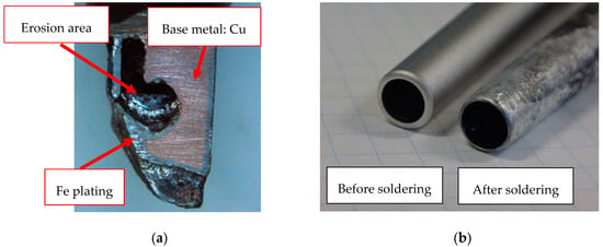
Figure 1.
Examples of erosion by molten lead-free solder. (a) Erosion of solder iron tip; (b) point soldering machine nozzle.
Since the solder iron tip and the point soldering nozzle are required to have a constant spread rate of molten solder, Fe is generally used as the material. Therefore, surface treatment by nitriding treatment as used in a flow soldering bath cannot be applied. In this study, two Fe composite plating layers were focused to realize both good wettability of SAC305 and good erosion resistance to SAC305. Graphite and a multi-walled carbon nanotube (MWCNT) [7,8,9] were used as filler materials in the composite plating layer. MWCNT is excellent regarding its strength properties, heat conduction properties and abrasion characteristics. Although graphite is inferior to MWCNT in terms of the previously mentioned material properties, it is inexpensive, more widely known and available. We have investigated the erosion-resistance characteristics of the Ni–MWCNT composite plating layer and reported that the amount of erosion of Ni–MWCNT in SAC305 is half that of the Ni plating layer [10]. The purpose of this study is to investigate the wettability of SAC305 to Fe–graphite and Fe–MWCNT composite plating layers and the erosion-resistance characteristics of both layers to SAC305. Moreover, the feasibility of them for use in the solder iron tip and the soldering machine nozzle were examined.
2. Experimental Procedure
2.1. Preparation of Specimens
Specimens were prepared using electrolytic Fe plating on the Cu plate (Hull cell test plate). The thickness of the plating layer was 100 μm. In this study, graphite (FUJIFILM Wako Pure Chemical, Graphite Powder 072-03845) with an average particle size of 45 μm and MWCNTs (Showa Denko, Osaka, Japan, VGCF-H) with an average length of 6 μm were prepared as filler materials in the composite plating layer. The concentration of graphite and MWCNT in the plating solution was 2 g/L. Sodium lauryl sulfate was also added at a concentration of 2 g/L in the solution as a dispersant for the carbon filler and a pit preventive agent. The temperature of the plating solution and the current density in plating were 313 K and 1 A/dm2, respectively. Furthermore, in order to disperse the carbon filler from the bottom of the bath in the plating solution, plating was conducted while stirring the solution with a magnetic stirrer at a speed of 250 rpm. The composite status of the carbon filler in the plating layer was investigated using a scanning electron microscope (SEM) and energy dispersive X-ray spectroscopy (EDS).
2.2. Solderability Test
To verify the solderability of molten SAC305 to the Fe–graphite and the Fe–MWCNT composite plating layers, the wettability characteristics were evaluated using the SAC305 solder wire including rosin (SENJU METAL INDUSTRY, Tokyo, Japan, RMA02-M705-φ0.6-P3). The spread test of molten solder was conducted according to the method specified in JIS-Z 3198-3, and the spread rate characteristics were examined. The test method is shown in Figure 2. The SAC305 solder wire with a volume of 39.7 mm3 was melted on Fe, Fe–graphite and Fe–MWCNT plating layers for 30 s at 573 K and 623 K. After cooling, the height of the solid solder was measured. After cooling, the spread rate of solder was calculated by Equations (1) and (2).
where SR is the spread rate, D is the diameter of the theoretical solder sphere, and H is the height of the measured solder. V is the solder volume used in the test.
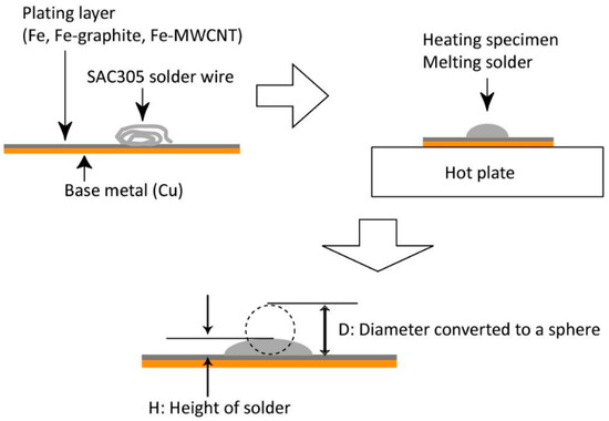
Figure 2.
Solder spread test method.
2.3. Erosion-Resistance Test
To evaluate the erosion characteristics of the Fe plating layer, Fe–graphite and Fe–MWCNT composite plating layers in molten SAC305, an erosion-resistance test was conducted. SAC305 solder wire with a volume of 39.7 mm3 was melted on each plating layer at 623 K for 7 h. After the test, the erosion depth was measured from the cross-section of the specimen using a SEM. Moreover, electron back scatter diffraction pattern (EBSD) analysis was performed for Fe–graphite and Fe–MWCNT composite plating layers. EBSD analysis was performed on a measurement field with a size of 5 μm × 4 μm using an acceleration voltage of 15 kV.
3. Results and Discussion
3.1. Microsturucture of Fe–Graphite and Fe–MWCNT Composite Plating Layers
The SEM images of the surfaces of the Fe–graphite and the Fe–MWCNT composite plating layers are shown in Figure 3. The graphite or the MWCNT is compounded on the plating surface, and Fe is deposited on top of this, covering it. The cross-sectional image of the Fe–graphite composite plating layer is shown in Figure 4. Figure 5 shows the magnified SEM image of the Fe–graphite composite plating layer and its EDS mapping analysis results. From both figures, it was found that fibrous graphite was compounded inside the Fe plating. Moreover, it was confirmed that fibrous graphite with a large aspect ratio can be uniformly dispersed within the Fe plating.
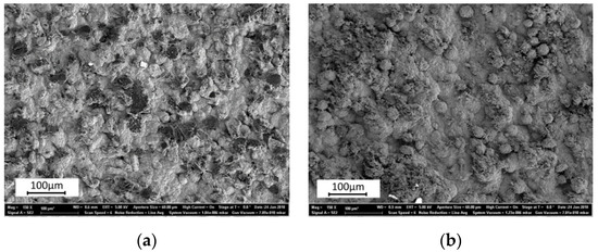
Figure 3.
SEM images of surfaces of plating layers: (a) Fe–graphite composite plating layer; (b) Fe–multi-walled carbon nanotube (MWCNT) composite plating layer.
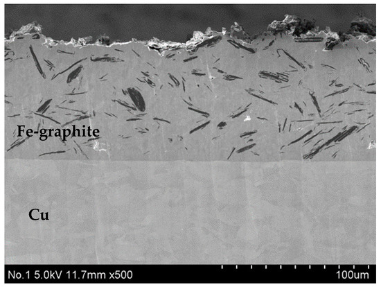
Figure 4.
Cross-sectional SEM image of Fe–graphite composite plating layer.
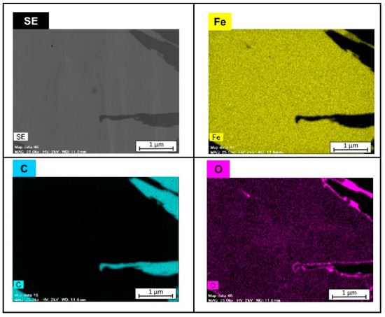
Figure 5.
SEM image of Fe–graphite composite plating layer and its EDS mapping analysis results.
The cross-sectional SEM image of the Fe–MWCNT composite plating layer is shown in Figure 6. Figure 7 shows the magnified SEM image of the Fe–MWCNT composite plating layer and its EDS mapping analysis results. From Figure 6, it was found that powder-like MWCNTs are grouped together in small patches. EDS mapping analysis results show that the powdery area consists of MWCNTs.
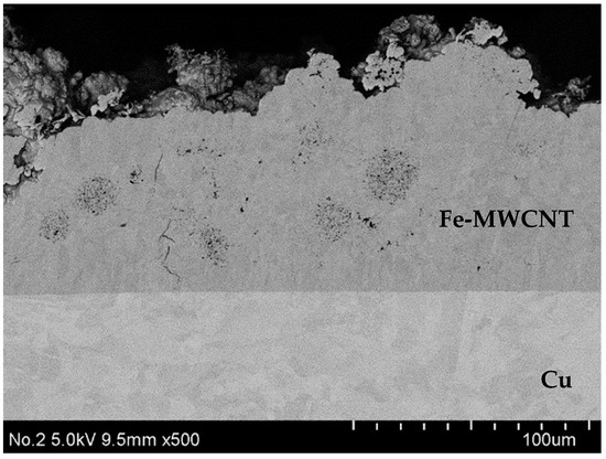
Figure 6.
Cross-sectional SEM image of Fe–MWCNT composite plating layer.
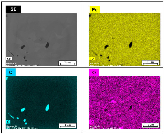
Figure 7.
SEM image of Fe–MWCNT composite plating layer and its EDS mapping analysis results.
3.2. Solderability Test
The results of the spread test of molten SAC305 are shown in Figure 8. In the Fe plating layer, good spread rates were obtained at both 573 K and 623 K. On the other hand, in the Fe–graphite and the Fe–MWCNT composite plating layers, the spread rates tended to be inferior at both temperatures compared to the Fe plating. It was found that graphite and MWCNT composite affect the spread properties of molten solder. A large amount of carbon filler is present in the plating layer and thus, the area where Fe and molten solder contact is relatively reduced. Consequently, the solderability of the carbon composite plating layer decreases. Generally, it is necessary for the spread rate to be greater than 50% to use the plating layer as a solder iron tip or a point soldering nozzle. As shown in Figure 8, since the spread rates of both the Fe–graphite and the Fe–MWCNT plating layers are greater than 50%, both plating layers can be applied to the solder iron tip and the point soldering machine nozzle.
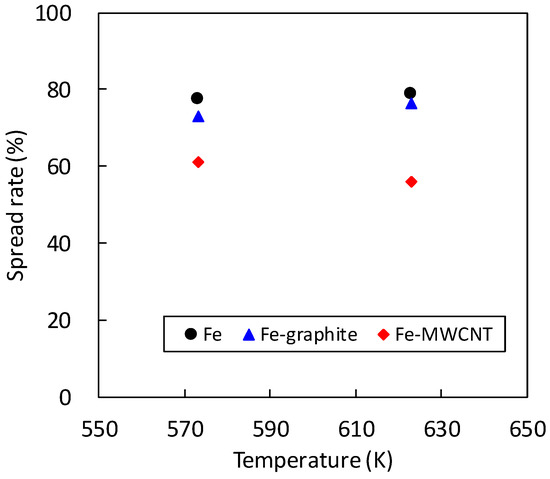
Figure 8.
Temperature dependence on spread rate for several plating layers.
3.3. Erosion-Resistance Test
The results of the erosion-resistance test are shown in Figure 9. The Fe–MWCNT composite plating layer shows the best erosion resistance in this study. The erosion depths of the Fe–graphite composite plating layer and the Fe plating layer were 10 and 100 times larger than that of the Fe–MWCNT composite plating layer, respectively. Since carbon does not react with solder, it does not erode even if it is in contact with molten solder for a long time. Thus, the diffusion of Fe into SAC305 was greatly reduced when composite carbon filler was combined with Fe. Since MWCNT has superior mechanical and thermal properties compared to graphite, the erosion resistance of the Fe–MWCNT plating layer is superior to that of the Fe–graphite one.
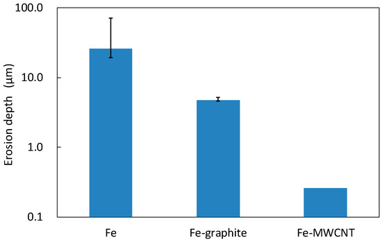
Figure 9.
Results of erosion-resistance test at 623 K.
EBSD analysis was carried out to analyze the improvement effect of the erosion resistance of the Fe–graphite and the Fe–MWCNT composite plating layers. EBSD analysis results are shown in Figure 10. A trace amount of Fe3C was detected at the interfaces of α-Fe grains. It is considered that a part of Fe and the compounded carbon filler reacts together, and thus, Fe3C compounds form by heating at 623 K. It has been reported that Fe3C particles suppress the diffusion of Fe into SAC305 solder [11,12]. In this study, a similar tendency was observed in the erosion-resistance test. Therefore, it is expected that the composite plating layer could possess good erosion resistance due to Fe3C by optimizing the plating conditions and annealing conditions.
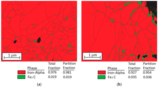
Figure 10.
Electron back scatter diffraction pattern (EBSD) analysis results for composite plating layers after heating at 623 K for 7 h. (a) Fe–graphite; (b) Fe–MWCNT. The α-Fe phase is indicated in red and the Fe3C phase is indicated in green.
4. Conclusions
In this study, the solderability and the erosion resistance of the Fe–carbon filler composite plating layers to SAC305 solder were investigated. Fe–graphite and Fe–MWCNT composite plating layers were fabricated and investigated. The obtained results were compared to those of the Fe plating layer. Based on the experimental results, the following conclusions are drawn.
- (1)
- Graphite and MWCNT were compounded not only on the Fe plating surface but also inside the plating film. Fibrous graphite can be uniformly dispersed in the Fe plating layer. MWCNTs are grouped together in small patches in the Fe plating layer.
- (2)
- Although the solderability of molten SAC305 decreased in the Fe–graphite and the Fe–MWCNT composite plating layers, the spread rates of SAC305 were more than 50%, which is a practical level. Therefore, they can be applied to the solder iron tip, the point soldering nozzle and so on.
- (3)
- From the results of the erosion-resistance test, it was shown that the Fe–graphite and the Fe–MWCNT composite plating layers have the effect of reducing erosion in molten SAC305 compared to the Fe plating layer.
- (4)
- EBSD analysis results revealed that a small amount of Fe3C compounds form in grain boundaries of α-Fe in both Fe–graphite and Fe–MWCNT plating layers. Since Fe3C particles suppress the diffusion of Fe into SAC305 solder, erosion-resistance characteristics can be further improved by forming Fe3C in the plating film efficiently.
- (5)
- By using not only a solder iron tip but also soldering bath made of Fe–MWCNT composite plating, it is expected that erosion can be suppressed, and it can be used for a longer time.
Author Contributions
J.W., K.H. and S.O. conceived and designed the experiments; J.W. performed the experiments; K.H., S.O. and S.Y. project administration; I.S. supervision; J.W. and I.S. wrote the paper; The authors have all read and approved the submitted version of the manuscript.
Funding
This research received no external funding.
Conflicts of Interest
The authors declare no conflict of interest.
References
- Morris, J.; O’Keefe, M.J. Equipment impacts of lead free wave soldering. Proc. APEX 2003 2003, 1, 1–9. [Google Scholar]
- Nishikawa, H.; Takemoto, T.; Kifune, K.; Uetani, T.; Sekimori, N. Effect of iron plating conditions on reaction in molten lead-free solder. Mater. Trans. 2004, 3, 741–746. [Google Scholar] [CrossRef][Green Version]
- Takemoto, T.; Takemoto, M. Dissolution of stainless steels in molten lead-free solders. Solder. Surf. Mt. Technol. 2006, 18, 24–30. [Google Scholar] [CrossRef]
- Serizawa, K.; Takemoto, T.; Yamamoto, K. Analysis of erosion mechanism and development of evaluation method for lead-free soldering equipment. In Proceedings of the 15th Symposium on Microjoining and Assembly Technology in Electronics, Yokohama, Japan, 29–30 January 2009; pp. 379–382. [Google Scholar]
- Takemoto, T.; Nishikawa, H.; Serizawa, K.; Yamamoto, K. Mechanism of damage of flow soldering bath by molten lead-free solder and its prevention methods. In Proceedings of the 15th Symposium on Microjoining and Assembly Technology in Electronics, Yokohama, Japan, 29–30 January 2009; pp. 383–386. [Google Scholar]
- Nishikawa, H.; Sabase, K.; Takemoto, T. Effect of some factor on erosion of stainless steel by molten lead-free solder. In Proceedings of the 15th Symposium on Microjoining and Assembly Technology in Electronics, Yokohama, Japan, 29–30 January 2009; pp. 387–390. [Google Scholar]
- Oberlin, A.; Endo, M.; Koyama, T. Filamentous growth of carbon through benzene decomposition. J. Cryst. Growth 1976, 32, 335–349. [Google Scholar] [CrossRef]
- Iijima, S. Helical microtubules of graphitic carbon. Nature 1991, 354, 56–58. [Google Scholar] [CrossRef]
- Iijima, S.; Ichihashi, T. Single-shell carbon nanotubes of 1-nm diameter. Nature 1993, 363, 603–605. [Google Scholar] [CrossRef]
- Miyazaki, M.; Watanabe, J.; Hatsuzawa, K.; Arai, S. Wettability and erosion resistance of Ni-MWCNT composite film for lead-free solder. In Proceedings of the 16th Symposium on Microjoining and Assembly Technology in Electronics, Yokohama, Japan, 2–3 February 2010; pp. 235–238. [Google Scholar]
- Yamauchi, A.; Sekito, Y.; Kurokawa, K.; Tanaka, J. Corrosion behavior of Fe-based alloys in molten lead-free solders. In Proceedings of the 17th Micro Electronics Symposium, Kobe, Japan, 13–14 September 2007; pp. 107–110. [Google Scholar]
- Kawamoto, T.; Yamauchi, A.; Kawakubo, S.; Irisawa, A.; Kurokawa, K.; Tanaka, J. Relationship between growth rate of interfacial reaction layer and carbon content in solder/carbon steel system. In Proceedings of the Japan Institute of Electronics Packaging, Yokohama, Japan, 8–10 March 2011; pp. 165–166. [Google Scholar]


© 2019 by the authors. Licensee MDPI, Basel, Switzerland. This article is an open access article distributed under the terms and conditions of the Creative Commons Attribution (CC BY) license (http://creativecommons.org/licenses/by/4.0/).