Thermal and Mechanical Analysis of a 72/48 Switched Reluctance Motor for Low-Speed Direct-Drive Mining Applications


Abstract
1. Introduction
2. 3D Thermal Model
- The insulating material completely covers windings;
- The stator and the rotor iron losses remain constant with uniform heat generation;
- Thermal conductivities of motor materials are isotropic.
2.1. Investigation of Losses (Heat Sources)
2.2. Heat Transfer Coefficient Boundary Conditions
2.2.1. The Effective Thermal Conductivity of Air Gap
2.2.2. Equivalent Model of Stator Windings
2.2.3. Heat Transfer Coefficient between External Frame and Ambient
2.2.4. Forced Convection Heat Transfer Coefficient between End Winding and End-Caps
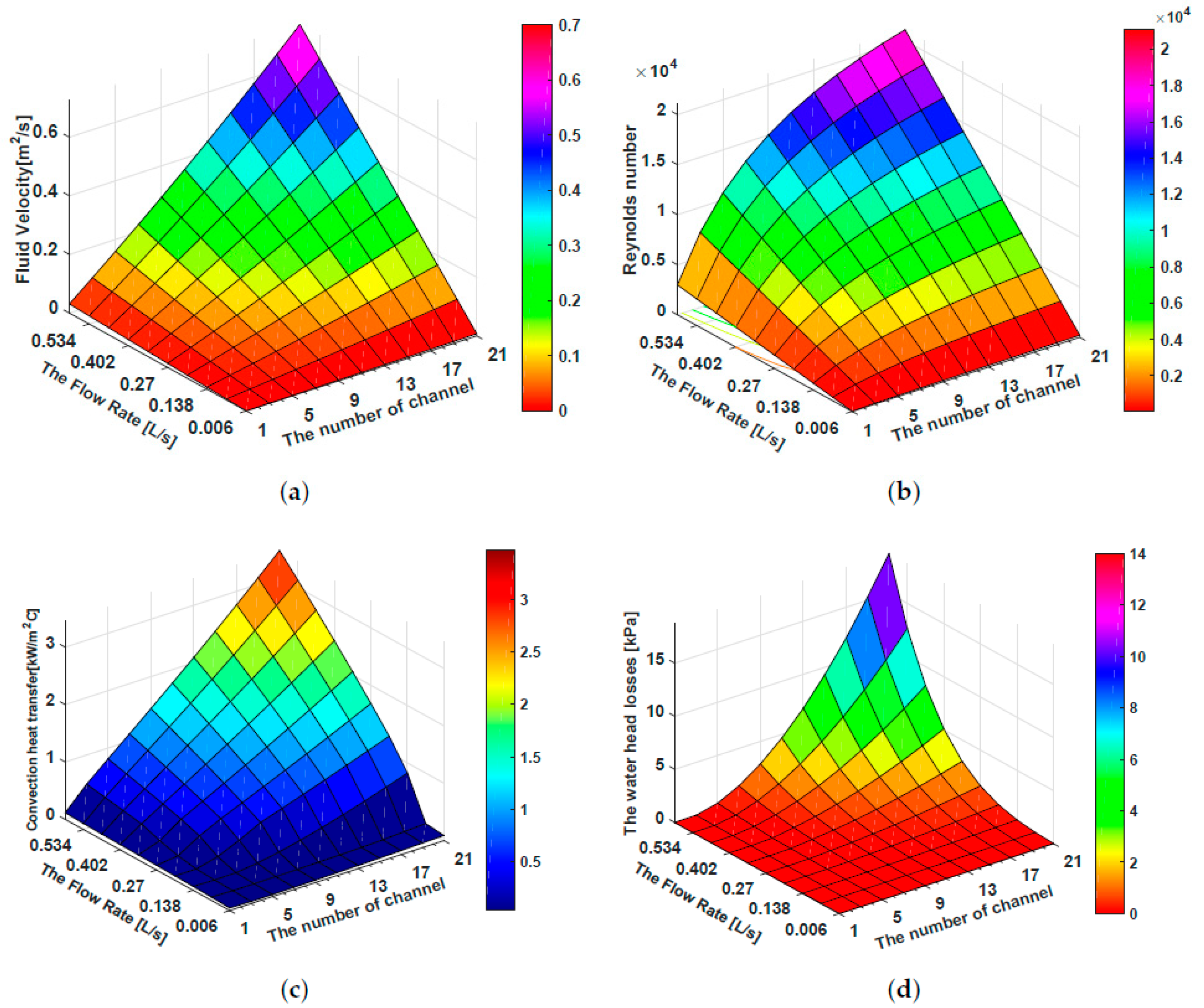
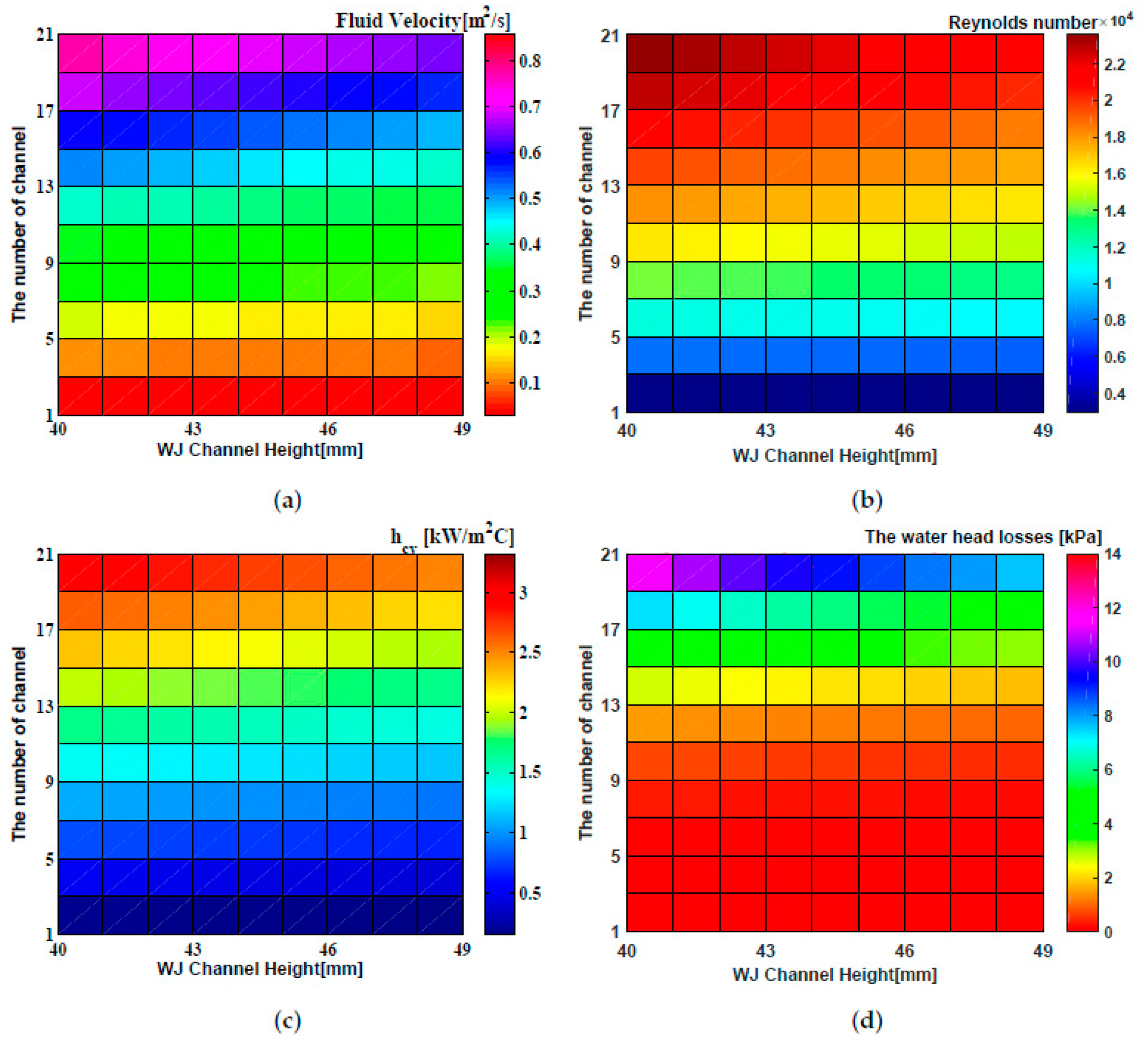
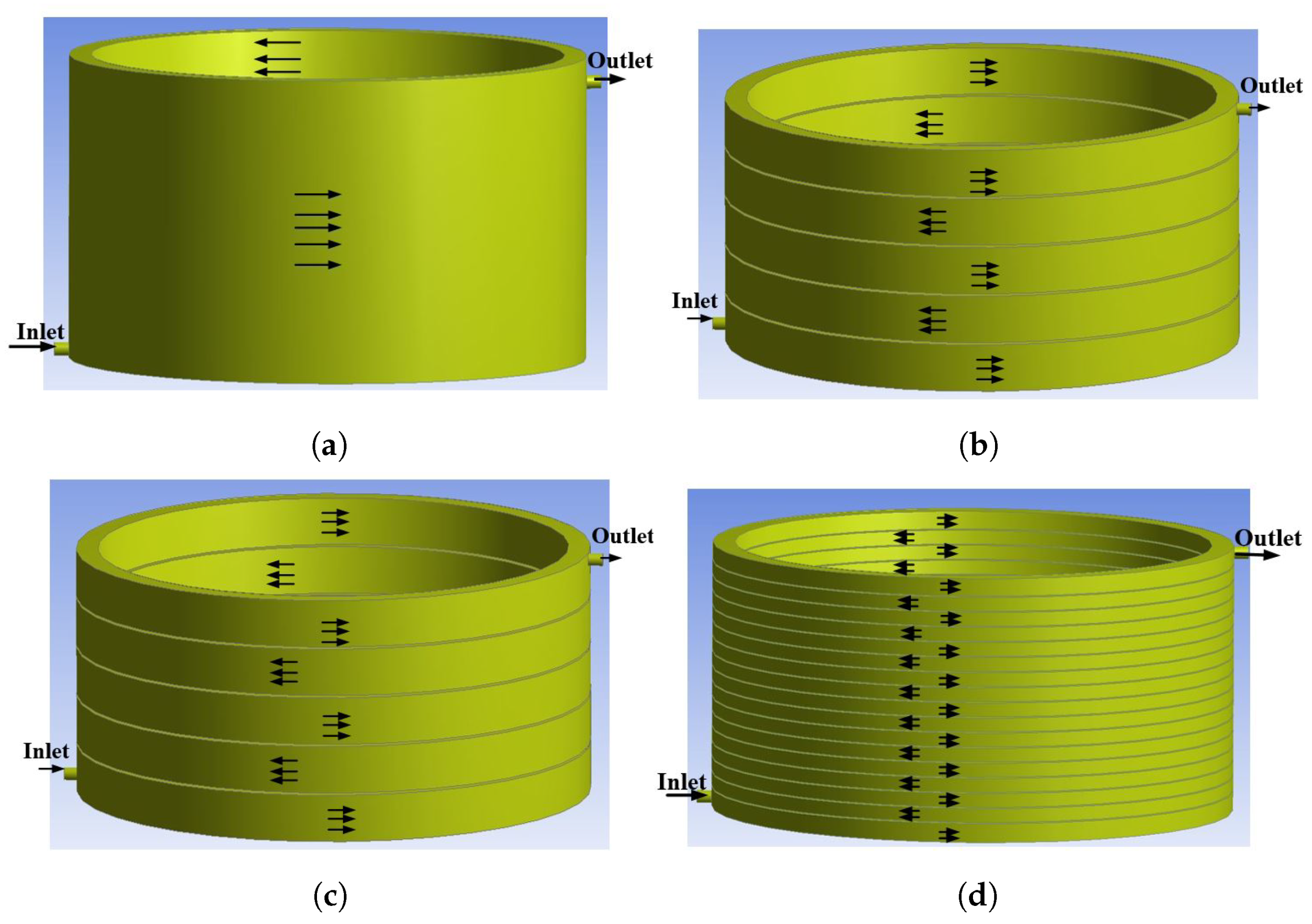
2.2.5. The Heat Transfer Coefficient of Water Jacket
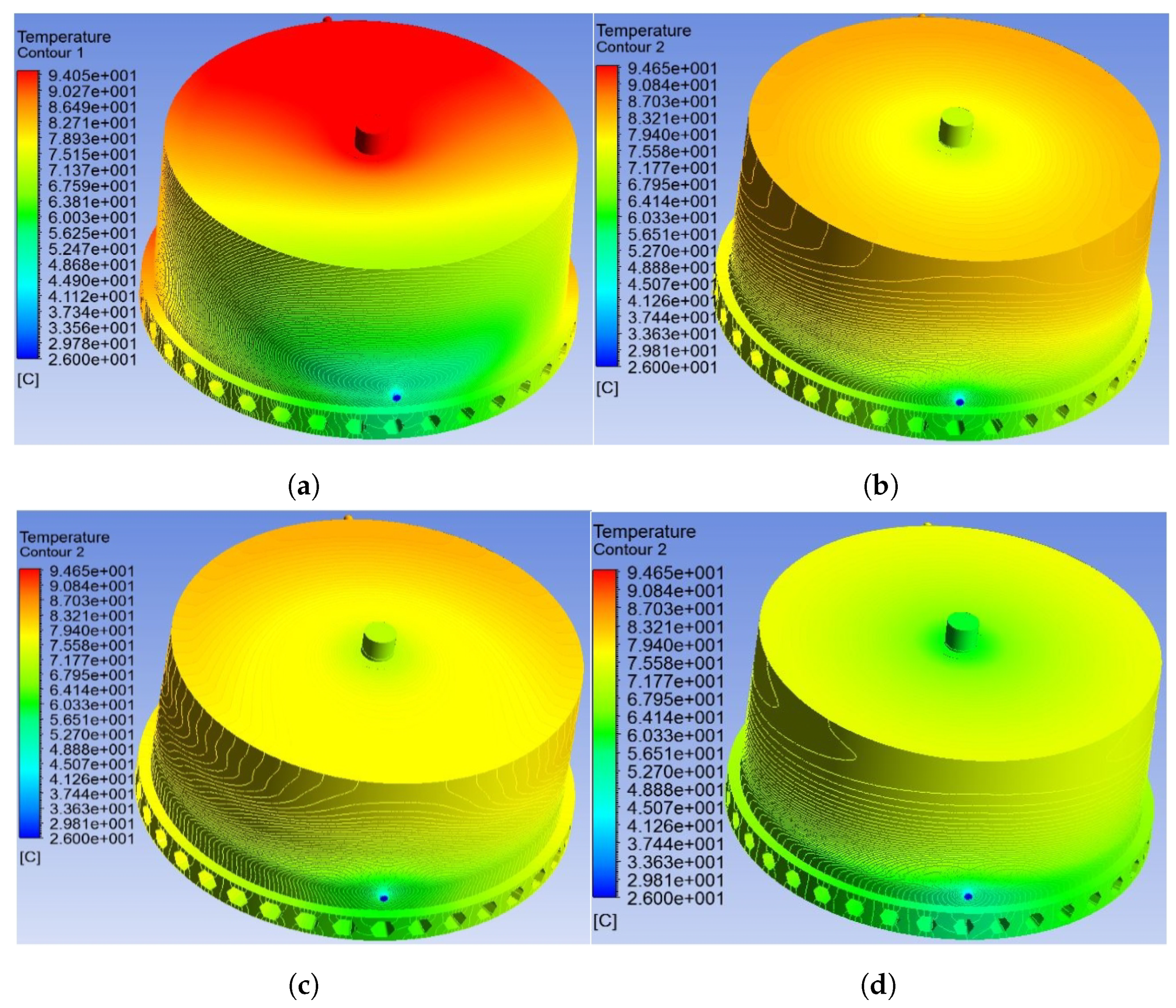
3. Thermal Analysis Methods
Numerical Analysis-CFD Analysis for Water Jacket
4. Mechanical Analysis
5. Experimental Setup
- (A)
- Three-Phase Power Quality Analyzer Fluke 434.
- (B)
- Digital Oscilloscope (Measured Current).
- (C)
- Digital Oscilloscope (Measured Voltage).
- (D)
- Power Supply and Control System.
- (E)
- Prototype SRM.
- (F)
- The Load Disc is Connected Directly to SRM.
- (G)
- Intelligent multi-channel Temperature inspection instrument (Temperature Monitor).
6. Conclusions
Author Contributions
Funding
Conflicts of Interest
References
- Elhomdy, E.; Li, G.; Liu, J.; Bukhari, S.; Cao, W. Design and Experimental Verification of a 72/48 Switched Reluctance Motor for Low-Speed Direct-Drive Mining Applications. Energies 2018, 11, 192. [Google Scholar] [CrossRef]
- Zhang, B.; Qu, R.; Fan, X.; Jin, W. Thermal and mechanical optimization of water jacket of permanent magnet synchronous machines for EV application. In Proceedings of the 2015 IEEE International Electric Machines and Drives Conference (IEMDC), Coeur d’Alene, ID, USA, 10–13 May 2015; pp. 1329–1335. [Google Scholar]
- Uharek, S.; Baratchi, S.; Jiu, Y.; Majed, A.; Mitchell, A.; Rebner, K.; Karnutsch, C.; Khoshmanesh, K. Water jacket systems for temperature control of Petri dish cell culture chambers. Appl. Sci. 2019, 9, 621. [Google Scholar] [CrossRef]
- Jebaseeli, E.; Paramasivam, S. Prediction of thermal behaviour of Switched Reluctance Machine using regression technique. In Proceedings of the 2015 IEEE International Conference on Electrical, Computer and Communication Technologies (ICECCT), Coimbatore, Tamilnadu, India, 5–7 March 2015; pp. 1–5. [Google Scholar]
- Rehman, Z.; Seong, K. Three-D Numerical Thermal Analysis of Electric Motor with Cooling Jacket. Energies 2018, 11, 92. [Google Scholar] [CrossRef]
- Boglietti, A.; Cavagnino, A.; Staton, D.; Shanel, M.; Mueller, M.; Mejuto, C. Evolution and Modern Approaches for Thermal Analysis of Electrical Machines. IEEE Trans. Ind. Electron. 2009, 56, 871–882. [Google Scholar] [CrossRef]
- Nategh, S.; Krings, A.; Zhe, H.; Wallmark, O.; Lindenmo, M. Evaluation of stator and rotor lamination materials for thermal management of a PMaSRM. In Proceedings of the 2012 XXth International Conference on Electrical Machines, Marseille, France, 2–5 September 2012; pp. 1309–1314. [Google Scholar]
- Chiu, H.; Jang, J.; Yan, W.; Shiao, R. Thermal performance analysis of a 30 kW switched reluctance motor. Int. J. Heat Mass Transf. 2017, 114, 145–154. [Google Scholar] [CrossRef]
- Hu, Y.; Ding, W.; Wang, T.; Li, S.; Yang, S.; Yin, Z. Investigation on a Multi-Mode Switched Reluctance Motor: Design, Optimization, Electromagnetic Analysis and Experiment. IEEE Trans. Ind. Electron. 2017, 64, 9886–9895. [Google Scholar] [CrossRef]
- Huang, Y.; Zhu, Z.; Guo, B.; Lin, H.; Fang, S. Design and thermal analysis on high torque low speed fractional-slot concentrated windings in-wheel traction motor. In Proceedings of the 2016 XXII International Conference on Electrical Machines (ICEM), Lausanne, Switzerland, 4–7 September 2016; pp. 1487–1492. [Google Scholar]
- Udhav, U.; Ashok, B.; Eshan, D.; Shahjahan, A.; Narayanan, G.; Pramod, K. Thermal and mechanical design considerations for a switched reluctance motor. In Proceedings of the 2016 7th India International Conference on Power Electronics (IICPE), Patiala, India, 17–19 November 2016; pp. 1–6. [Google Scholar]
- Li, S.; Zhang, S.; Habetler, T.G.; Harley, R.G. A survey of electromagnetic Thermal modeling and design optimization of switched reluctance machines. In Proceedings of the 2017 IEEE International Electric Machines and Drives Conference (IEMDC), Miami, FL, USA, 21–24 May 2017; pp. 1–7. [Google Scholar]
- Kasprzak, M.; Jiang, J.W.; Bilgin, B.; Emadi, A. Thermal analysis of a three-phase 24/16 switched reluctance machine used in HEVs. In Proceedings of the 2016 IEEE Energy Conversion Congress and Exposition (ECCE), Milwaukee, WI, USA, 18–22 September 2016; pp. 1–7. [Google Scholar]
- Faiz, J.; Ganji, B.; Carstensen, C.; De Doncker, R. Loss prediction in switched reluctance motors using finite element method. Eur. Trans. Electr. Power 2009, 19, 731–748. [Google Scholar] [CrossRef]
- Srinivas, N.; Arumugam, R. Analysis and characterization of switched reluctance motors: Part II Flow, thermal, and vibration analyses. IEEE Trans. Magn. 2005, 41, 1321–1332. [Google Scholar] [CrossRef]
- Tiberiu, R.; Adrian, P.; Lorand, S. Noise Harshness and Vibration Characterization of Switched Reluctance Motors. J. Comp. Sci. Cont. Syst. 2016, 9, 34. [Google Scholar]
- Gieras, J.; Wang, C.; Lai, C. Noise of Polyphase Electric Motors; CRC Press: Boca Raton, FL, USA, December 2005; ISBN 9780824723811. [Google Scholar]
- Ru, L. Comparison of vibration between an evaporative cooling switched reluctance motor and a conventional switched reluctance motor. In Proceedings of the 2018 21st International Conference on Electrical Machines and Systems (ICEMS), Jeju, Korea, 7–10 October 2018; pp. 2483–2486. [Google Scholar]
- Prabhu, S.; Chandrasekar, V.; Karthikeyan, P.; Lenin, N.C.; Arumugam, R. Vibration and thermal analysis of switched reluctance hub motor. Eur. J. Sci. Res. 2012, 68, 12–20. [Google Scholar]
- Ebrahimi, Y.; Feyzi, R. Lumped Parameter Thermal Model for Axial Flux Switched Reluctance Motors. Electr. Power Compos. Syst. 2018, 45, 1–9. [Google Scholar] [CrossRef]
- Jebaseeli, E.; Paramasivam, S. Steady state and transient thermal analysis of switched reluctance machine. Int. J. Comput. Electr. Eng. 2012, 4, 794. [Google Scholar] [CrossRef]
- Siadatan, A.; Mirimani, S.; Shamei, M.; Khalili, T. Thermal stability analysis of 6/4 switch reluctance motor using finite element method. In Proceedings of the 2016 International Symposium on Power Electronics, Electrical Drives, Automation and Motion (SPEEDAM), Anacapri, Italy, 22–24 June 2016; pp. 382–387. [Google Scholar]
- Chong, Y.C. Thermal Analysis and Air Flow Modelling of Electrical Machines. Ph.D. Thesis, University of Edinburgh, Edinburgh, UK, 2015. [Google Scholar]
- Wang, S.W.; Zhang, Y.; Hu, J. Thermal Analysis of Water-Cooled Permanent Magnet Synchronous Motor for Electric Vehicles. Appl. Mech. Mater. 2014, 610, 129–135. [Google Scholar] [CrossRef]
- Ying, X.; Jinpeng, G.; Peng, C.; Zhiwei, L. Coupled Fluid-Thermal Analysis for Induction Motors with Broken Bars Operating under the Rated Load. Energies 2018, 11, 2024. [Google Scholar]
- Pillay, P.; Cai, W. An investigation into vibration in switched reluctance motors. IEEE Trans. Ind. Appl. 1999, 35, 589–596. [Google Scholar] [CrossRef]
- Lecointe, J.; Romary, R.; Brudny, J.; Czapla, T. Five methods of stator natural frequency determination: case of induction and switched reluctance machines. Mech. Syst. Signal Proc. 2004, 18, 1133–1159. [Google Scholar] [CrossRef]
- Senousy, M.; Larsen, P.; Ding, P. Electromagnetics, Structural Harmonics and Acoustics Coupled Simulation on the Stator of an Electric Motor. Int. J. Passeng. Cars Mech. Syst. 2014, 18, 822–828. [Google Scholar] [CrossRef]
- Krishnan, R. Switched Reluctance Motor Drives: Modeling, Simulation, Analysis, Design, and Applications; CRC Press: Boca Raton, FL, USA, 2001; ISBN 0849308380. [Google Scholar]
- Torrent, M.; Andrada, P.; Blanque, B.; Martinez, E.; Perat, J.; Sanchez, J. Method for estimating core losses in switched reluctance motors. Eur. Trans. Electr. Power 2013, 21, 757–771. [Google Scholar] [CrossRef]
- Pyrhonen, J.; Jokinen, T.; Hrabovcova, V. Design of Rotating Electrical Machines; John Wiley & Sons: New York, NY, USA, 2013; ISBN 978-1-118-58157-5. [Google Scholar]
- Boglietti, A.; Cavagnino, A.; Staton, D. Determination of Critical Parameters in Electrical Machine Thermal Models. IEEE Trans. Ind. Appl. 2008, 44, 1150–1159. [Google Scholar] [CrossRef]
- Kays, W.; Crawford, E.; Weigand, B. Convective Heat and Mass Transfer; McGraw-Hill Science/Engineering/Math: New York, NY, USA, 2005; ISBN 100072990732. [Google Scholar]
- Romanazzi, P.; Howey, A. Air gap convection in a switched reluctance machine. In Proceedings of the 2015 Tenth International Conference on Ecological Vehicles and Renewable Energies (EVER), Monte-Carlo, Monaco, France, 31 March–2 April 2015; pp. 1–7. [Google Scholar]
- Hosain, M.; Fdhila, R.; Rönnberg, K. Air-gap Flow and Thermal Analysis of Rotating Machines using CFD. Energy Procedia 2017, 105, 5153–5159. [Google Scholar] [CrossRef]
- Cuiping, L.; Yulong, P.; Ronggang, N.; Shukang, C. Analysis of 3D static temperature field of water cooling induction motor in mini electric vehicle. In Proceedings of the 2011 International Conference on Electrical Machines and Systems, Beijing, China, 20–23 August 2011; pp. 1–5. [Google Scholar]
- Bergman, T.; Incropera, F.; Lavine, A.; DeWitt, D. Introduction to Heat Transfer; John Wiley & Sons: Hoboken, NJ, USA, 2011; ISBN 10 0470917865. [Google Scholar]
- White, F.; Corfield, I. Viscous Fluid Flow; McGraw-Hill: New York, NY, USA, 2006; ISBN 10 0072402318. [Google Scholar]
- Park, C.-B. Thermal analysis of IPMSM with water cooling jacket for railway vehicles. J. Electr. Eng. Technol. 2014, 9, 882–887. [Google Scholar] [CrossRef]
- Chen, E.; Rupertus, G. Development of water jacket cooled motor and its applications in cement industry. In Proceedings of the 2017 IEEE-IAS/PCA Cement Industry Technical Conference, Calgary, AB, Canada, 21–25 May 2017; pp. 1–18. [Google Scholar]
- Zhang, H.; Gao, C.; Wang, S. Analysis of radial force for switched reluctance motor. In Proceedings of the 2013 IEEE International Conference on Applied Superconductivity and Electromagnetic Devices, Beijing, China, 25–27 October 2013; pp. 418–419. [Google Scholar]


| Components | Materials | Density [kg/m] | Specific Heat [J/kg/C] | Thermal Conductivity [W/m·C] | Young’s Modulus [GPa] | Poisson’s Ratio |
|---|---|---|---|---|---|---|
| Cover and Chassis | Aluminium alloy | 2790 | 833 | 168 | 69 | 0.33 |
| Stator/Rotor core | M19-29gauge steel | 7800 | 460 | 28 | 200 | 0.29 |
| Winding | Copper ( Pure) | 8933 | 385 | 401 | 116 | 0.35 |
| Insulating layer | Composite material | 1400 | 1000 | 0.21 | 3.5 | 0.3 |
| Parameter | Value | Parameter | Value |
|---|---|---|---|
| Number of stator poles | 72 | Stack length [mm] | 340 |
| Number of rotor poles | 48 | Air gap length [mm] | 1 |
| Stator out diameter [mm] | 1000 | Rotor out diameter [mm] | 798 |
| Stator pole arc angle [deg] | 2.85 | Rotor pole arc angle [deg] | 3.15 |
| Stator pole width [mm] | 19.89 | Rotor pole width [mm] | 21.93 |
| Stator yoke thickness [mm] | 18 | Rotor yoke thickness [mm] | 20 |
| Stator slot depth [mm] | 82 | Rotor slot depth [mm] | 39 |
| Number of turns per pole [Turns] | 15 | Shaft diameter [mm] | 680 |
| Description | Value | Unit |
|---|---|---|
| Hysteresis coefficient, | 165.36 | [Ws/Tm] |
| Electric conductivity, | 1.96 × 10 | [S/m] |
| Lamination thickness, d | 0.35 × 10 | [m] |
| Excess loss coefficient, | 0.517 | [W/Tsm] |
| Mass density, | 7800 | [kg/m] |
| Portions | Values of losses [W] | Weight [kg] |
|---|---|---|
| Windings | 6560 | 199.6 |
| Stator | 1445 | 436.6 |
| Rotor | 650 | 214.6 |
| The Total | 8655 | 850.8 |
| WJ Channel | The Range of kW/mC | WJ Configurations | The Range of kW/mC |
|---|---|---|---|
| 1 channel | 0 < < 0.4 | 3 channels | 0.4 < < 0.7 |
| 5 channels | 0.7 < < 1 | 7 channels | 1 < < 1.3 |
| 9 channels | 1.3 < < 1.6 | 11 channels | 1.6 < < 1.9 |
| 13 channels | 1.9 < < 2.2 | 15 channels | 2.2 < < 2.5 |
| 17 channels | 2.5 < < 2.8 | 19 channels | 2.8 < < 3.1 |
| WJ Channel | H [mm] | W [mm] |
|---|---|---|
| 1 channel | 47 | 380 |
| 5 channels | 47 | 74.4 |
| 9 channels | 47 | 40.44 |
| 17 channels | 47 | 20.47 |
| WJ Configurations | Analytically W/mC | Numerically W/mC |
|---|---|---|
| 1 channel | 351 | 349 |
| 5 channels | 722 | 718 |
| 9 channels | 1630 | 1621 |
| 17 channels | 2589 | 2578 |
| Mode Shape | M-1 | M-2 | M-3 | M-4 | M-5 | M-6 |
|---|---|---|---|---|---|---|
| Natural frequency of SRM with spoke shaft (Hz) | 508.64 | 516.56 | 748.64 | 800.23 | 859.18 | 872.78 |
| Natural frequency of SRM with solid shaft (Hz) | 407.72 | 412.14 | 423.85 | 440.82 | 463.01 | 549.34 |
| Mode Shape | M-1 | M-2 | ||
|---|---|---|---|---|
| Min | Max | Min | Max | |
| Deformation of the SRM with spoke shaft (mm) | 0 | 1.59 | 0 | 1.62 |
| Deformation of the SRM with solid shaft (mm) | 0 | 1.09 | 0 | 1.54 |
| PT100 | Location |
|---|---|
| A | End Winding Phase A |
| B | End Winding Phase B |
| C | End Winding Phase C |
| 1 | Stator Tooth Middle |
| 1 | Stator Tooth Tope |
| Portion of Sensor | A | B | C | 1 | 2 |
|---|---|---|---|---|---|
| Experiment data [°C] | 78 | 78 | 78 | 75.8 | 75 |
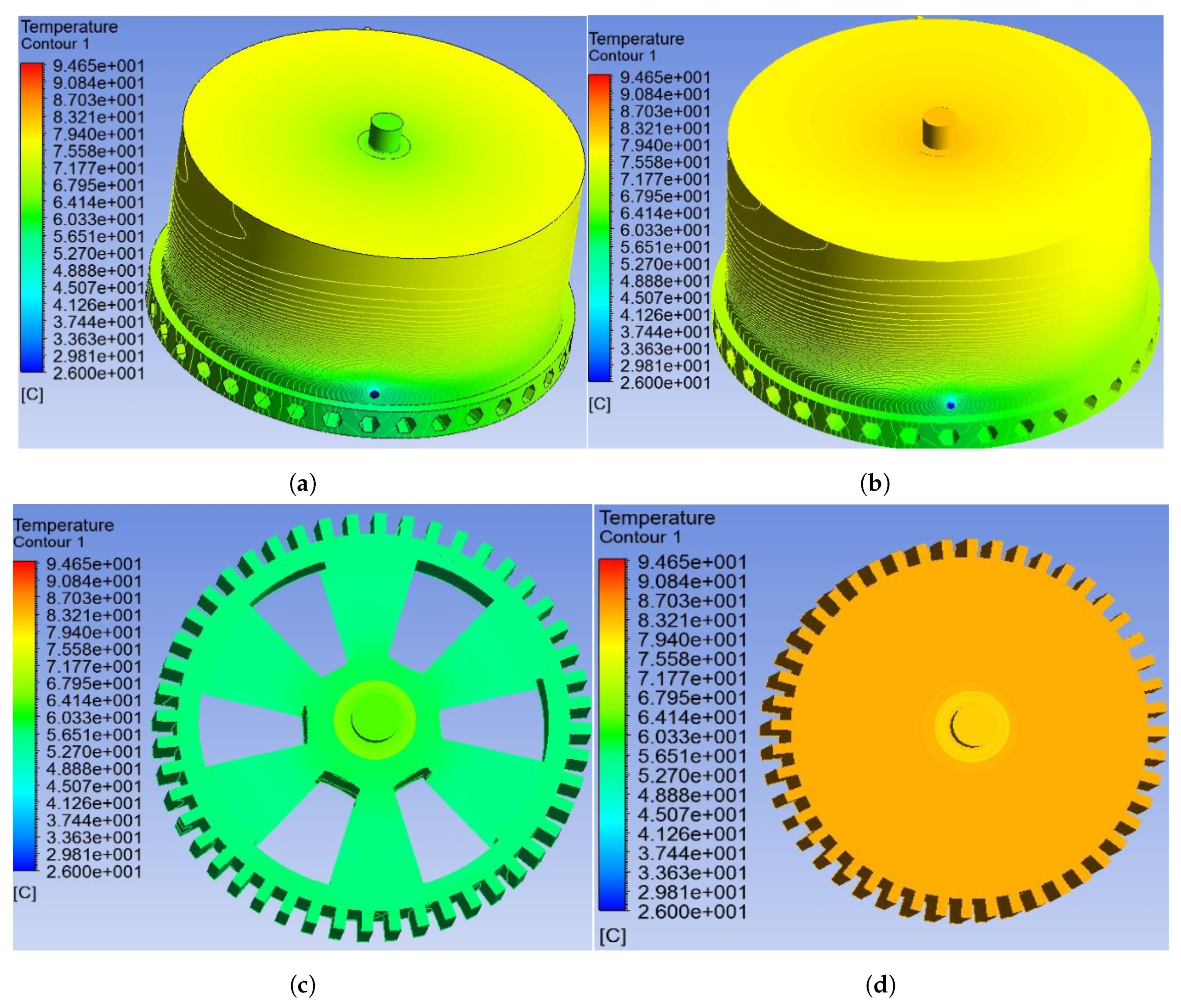
| CFD of Figure 8d and Figure 9d [°C] | 77.5 | 77.5 | 77.5 | 75.4 | 74.7 |
| Mode Shape | Experimental Modes (Hz) | FEM Modes of Spoke Shaft (Hz) | Error (%) |
|---|---|---|---|
| M-1 | 490.3 | 508.64 | 3.7 |
| M-2 | 501.4 | 516.56 | 3.02 |
| M-3 | 729.7 | 748.64 | 2.59 |
| M-4 | 780.5 | 800.23 | 2.52 |
| M-5 | 842.2 | 859.18 | 2.02 |
| M-6 | 848.1 | 872.78 | 2.91 |
© 2019 by the authors. Licensee MDPI, Basel, Switzerland. This article is an open access article distributed under the terms and conditions of the Creative Commons Attribution (CC BY) license (http://creativecommons.org/licenses/by/4.0/).
Share and Cite
Elhomdy, E.; Liu, Z.; Li, G. Thermal and Mechanical Analysis of a 72/48 Switched Reluctance Motor for Low-Speed Direct-Drive Mining Applications. Appl. Sci. 2019, 9, 2722. https://doi.org/10.3390/app9132722
Elhomdy E, Liu Z, Li G. Thermal and Mechanical Analysis of a 72/48 Switched Reluctance Motor for Low-Speed Direct-Drive Mining Applications. Applied Sciences. 2019; 9(13):2722. https://doi.org/10.3390/app9132722
Chicago/Turabian StyleElhomdy, Esmail, Zheng Liu, and Guofeng Li. 2019. "Thermal and Mechanical Analysis of a 72/48 Switched Reluctance Motor for Low-Speed Direct-Drive Mining Applications" Applied Sciences 9, no. 13: 2722. https://doi.org/10.3390/app9132722
APA StyleElhomdy, E., Liu, Z., & Li, G. (2019). Thermal and Mechanical Analysis of a 72/48 Switched Reluctance Motor for Low-Speed Direct-Drive Mining Applications. Applied Sciences, 9(13), 2722. https://doi.org/10.3390/app9132722