Polymer-Based Microring Resonator with the Multimode Interference Coupler Operating at Very-Near-Infrared Wavelengths

 , and
, and 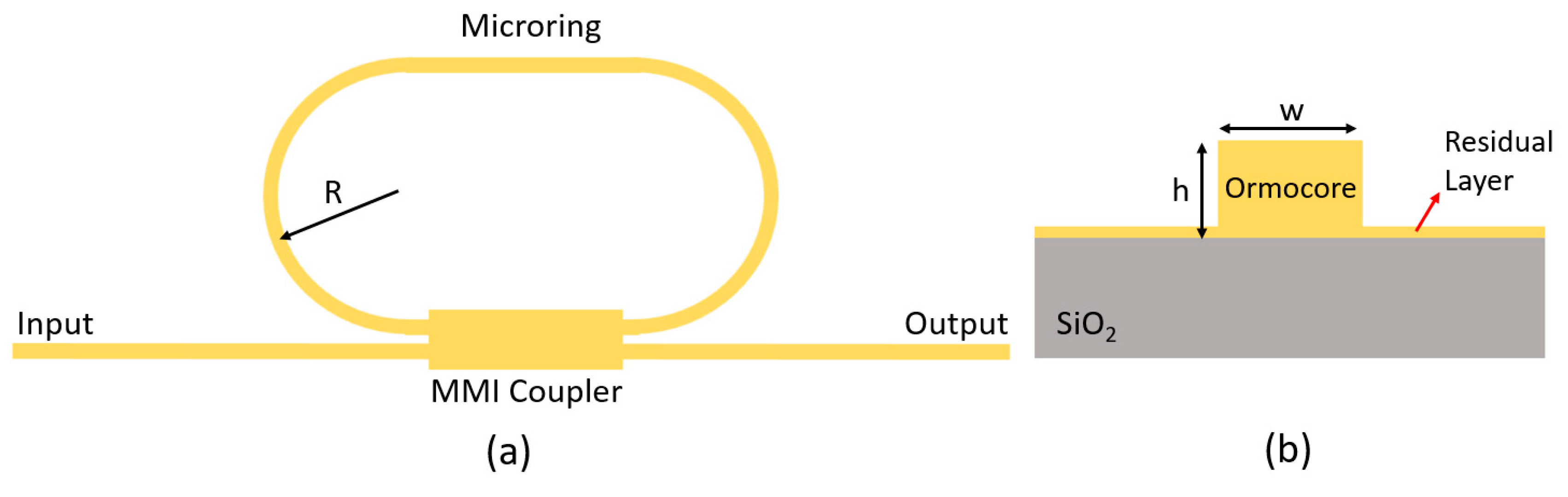
Abstract
1. Introduction
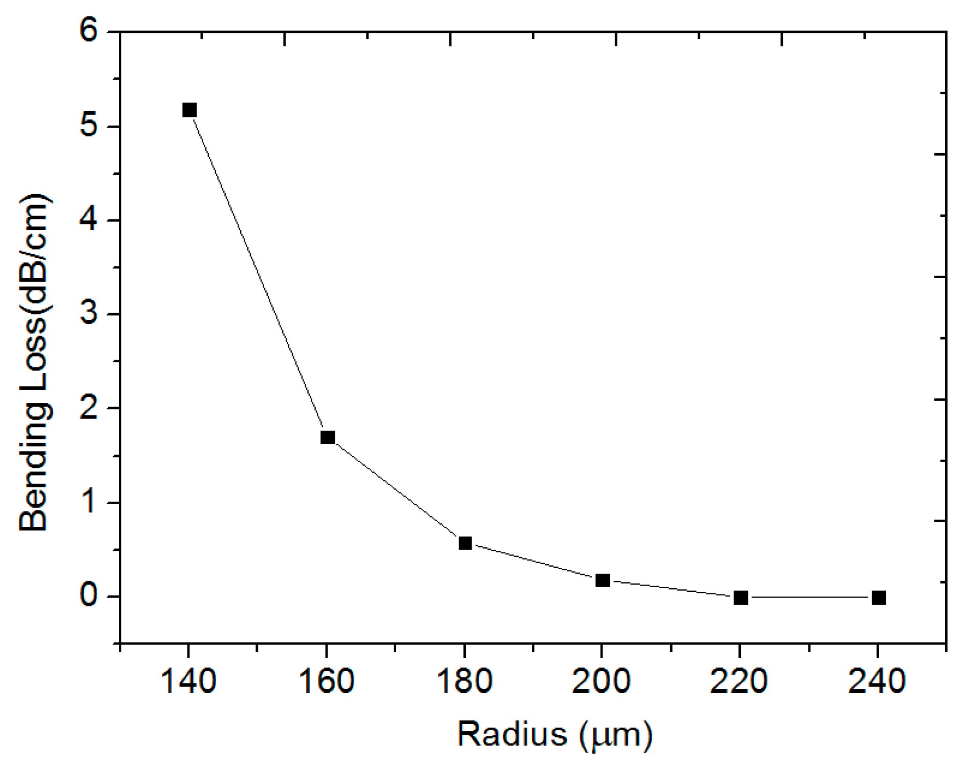
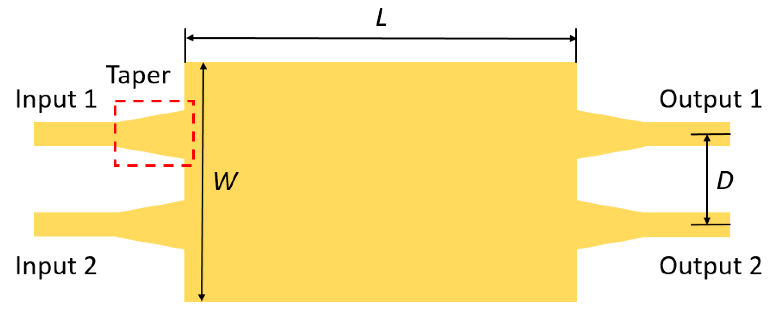
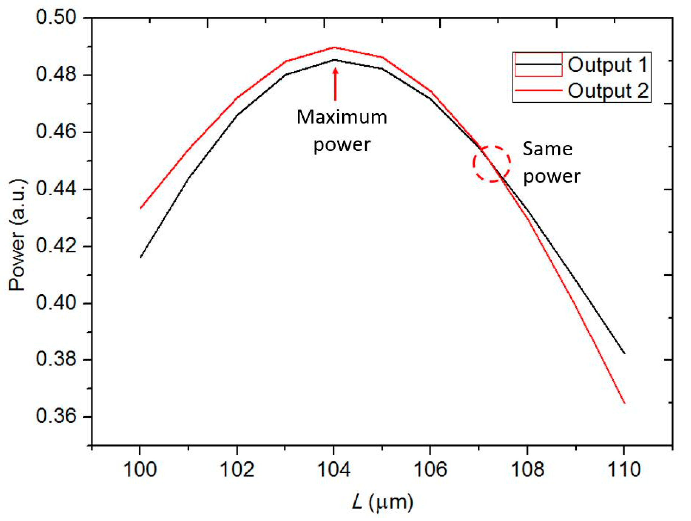
2. Structure and Design
3. Fabrication and Characterization
4. Measurement and Result Analysis
5. Conclusions
Author Contributions
Funding
Conflicts of Interest
References
- Jayatilleka, H.; Murray, K.; Caverley, M.; Jaeger, N.A.F.; Chrostowski, L.; Shekhar, S. Crosstalk in SOI Microring Resonator-Based Filters. J. Lightwave Technol. 2016, 34, 2886–2896. [Google Scholar] [CrossRef]
- Qiu, H.; Zhou, F.; Qie, J.; Yao, Y.; Hu, X.; Zhang, Y.; Xiao, X.; Yu, Y.; Dong, J.; Zhang, X. A Continuously Tunable Sub-Gigahertz Microwave Photonic Bandpass Filter Based on an Ultra-High-Q Silicon Microring Resonator. J. Lightwave Technol. 2018, 36, 4312–4318. [Google Scholar] [CrossRef]
- Dubé-Demers, R.; St-Yves, J.; Bois, A.; Zhong, Q.; Caverley, M.; Wang, Y.; Chrostowski, L.; LaRochelle, S.; Plant, D.V.; Shi, W. Analytical Modeling of Silicon Microring and Microdisk Modulators with Electrical and Optical Dynamics. J. Lightwave Technol. 2015, 33, 4240–4252. [Google Scholar] [CrossRef]
- Chang, C.-M.; de Valicourt, G.; Chandrasekhar, S.; Dong, P. Differential Microring Modulators for Intensity and Phase Modulation: Theory and Experiments. J. Lightwave Technol. 2017, 35, 3116–3124. [Google Scholar] [CrossRef]
- Arbabi, A.; Kamali, S.M.; Arbabi, E.; Griffin, B.G.; Goddard, L.L. Grating integrated single mode microring laser. Opt. Express 2015, 23, 5335–5347. [Google Scholar] [CrossRef] [PubMed]
- Sui, S.-S.; Tang, M.-Y.; Yang, Y.-D.; Xiao, J.-L.; Du, Y.; Huang, Y.-Z. Investigation of hybrid microring lasers adhesively bonded on silicon wafer. Photonics Res. 2015, 3, 289–295. [Google Scholar] [CrossRef]
- Vos, K.D.; Bartolozzi, I.; Schacht, E.; Bienstman, P.; Baets, R. Silicon-on-Insulator microring resonator for sensitive and label-free biosensing. Opt. Express 2007, 15, 7610–7615. [Google Scholar] [CrossRef]
- Mi, G.; Horvath, C.; Aktary, M.; Van, V. Silicon microring refractometric sensor for atmospheric CO(2) gas monitoring. Opt. Express 2016, 24, 1773–1780. [Google Scholar] [CrossRef]
- Wang, L.; Ren, J.; Han, X.; Claes, T.; Jian, X.; Bienstman, P.; Baets, R.; Zhao, M.; Morthier, G. A label-free optical biosensor built on a low-cost polymer platform. IEEE Photonics J. 2012, 4, 920–930. [Google Scholar] [CrossRef]
- Shahoei, H.; Xu, D.X.; Schmid, J.H.; Yao, J. Photonic fractional-order differentiator using an soi microring resonator with an MMI coupler. IEEE Photonics Technol. Lett. 2013, 25, 1408–1411. [Google Scholar] [CrossRef]
- Xu, D.X.; Vachon, M.; Densmore, A.; Ma, R.; Schmid, J.H. Label-free biosensor array based on silicon-on-insulator ring resonators addressed using a WDM approach. Opt. Lett. 2010, 35, 2771–2773. [Google Scholar] [CrossRef] [PubMed]
- Ymeti, A.; Kanger, J.S.; Greve, J.; Lambeck, P.V.; Wijn, R.; Heideman, R.G. Realization of a multichannel integrated Young interferometer chemical sensor. Appl. Opt. 2003, 42, 5649–5660. [Google Scholar] [CrossRef] [PubMed]
- Ksendzov, A.; Lin, Y. Integrated optics ring-resonator sensors for protein detection. Opt. Lett. 2005, 30, 3344–3346. [Google Scholar] [CrossRef] [PubMed]
- Maxwell, A.; Huang, S.W.; Ling, T.; Kim, J.S.; Ashkenazi, S.; Guo, L.J. Polymer microring resonators for high-frequency ultrasound detection and imaging. IEEE J. Sel. Top. Quantum Electron. 2008, 14, 191–197. [Google Scholar] [CrossRef] [PubMed]
- Salleh, M.H.M.; Glidle, A.; Sorel, M.; Reboud, J.; Cooper, J.M. Polymer dual ring resonators for label-free optical biosensing using microfluidics. Chem. Commun. 2013, 49, 3095. [Google Scholar] [CrossRef] [PubMed]
- Girault, P.; Lorrain, N.; Poffo, L.; Guendouz, M.; Lemaitre, J.; Carré, C.; Gadonna, M.; Bosc, D.; Vignaud, G. Integrated polymer micro-ring resonators for optical sensing applications. J. Appl. Phys. 2015, 117, 104504. [Google Scholar] [CrossRef]
- Rezem, M.; Günther, A.; Roth, B.; Reithmeier, E.; Rahlves, M. Low-Cost Fabrication of All-Polymer Components for Integrated Photonics. J. Lightwave Technol. 2017, 35, 299–308. [Google Scholar] [CrossRef]
- Shi, F.; Bamiedakis, N.; Vasil’ev, P.P.; Penty, R.V.; White, I.H.; Chu, D. Flexible multimode polymer waveguide arrays for versatile high-speed short-reach communication links. J. Lightwave Technol. 2018, 36, 2685–2693. [Google Scholar] [CrossRef]
- Ma, H.; Jen, A.K.Y.; Dalton, L.R. Polymer-based optical waveguides: Materials, processing, and devices. Adv. Mater. 2010, 14, 1339–1365. [Google Scholar] [CrossRef]
- Eldada, L.; Shacklette, L.W. Advances in polymer integrated optics. IEEE J. Sel. Top. Quantum Electron. 2000, 6, 54–68. [Google Scholar] [CrossRef]
- Kirchner, R.; Finn, A.; Landgraf, R.; Nueske, L.; Teng, L.; Vogler, M.; Fischer, W.-J. Direct UV-Imprinting of Hybrid-Polymer Photonic Microring Resonators and Their Characterization. J. Lightwave Technol. 2014, 32, 1674–1681. [Google Scholar] [CrossRef]
- Zgraggen, E.; Soganci, I.M.; Horst, F.; Porta, A.L.; Dangel, R.; Offrein, B.J.; Snow, S.A.; Young, J.K.; Swatowski, B.W.; Amb, C.M.; et al. Laser direct writing of single-mode polysiloxane optical waveguides and devices. J. Lightwave Technol. 2014, 32, 3036–3042. [Google Scholar] [CrossRef]
- Ting, H.; Steve, M.; Mathew, Z.; Robbie, C.; Barry, L.D. Low loss high index contrast nanoimprinted polysiloxane waveguides. Opt. Express 2009, 17, 2623. [Google Scholar]
- Goh, S.J.; Bastiaens, H.J.M.; Vratzov, B.; Huang, Q.; Bijkerk, F.; Boller, K.J. Fabrication and characterization of free-standing, high-line-density transmission gratings for the vacuum UV to soft X-ray range. Opt. Express 2015, 23, 4421–4434. [Google Scholar] [CrossRef] [PubMed]
- Han, X.Y.; Wu, Z.L.; Yang, S.C.; Shen, F.F.; Liang, Y.X.; Wang, L.H.; Wang, J.Y.; Ren, J.; Jia, L.Y.; Zhang, H. Recent Progress of Imprinted Polymer Photonic Waveguide Devices and Applications. Polymers 2018, 10, 603. [Google Scholar] [CrossRef] [PubMed]
- Williams, S.S.; Retterer, S.; Lopez, R.; Ruiz, R.; Samulski, E.T.; Desimone, J.M. High-Resolution PFPE-based Molding Techniques for Nanofabrication of High-Pattern Density, Sub-20 nm Features: A Fundamental Materials Approach. Nano Lett. 2010, 10, 1421–1428. [Google Scholar] [CrossRef] [PubMed]
- Jacob, J.; Yuying, T.; Rothstein, J.P.; Watkins, J.J.; Carter, K.R. Large-area, continuous roll-to-roll nanoimprinting with PFPE composite molds. Nanotechnology 2013, 24, 505307. [Google Scholar]
- Hiltunen, M.; Hiltunen, J.; Stenberg, P.; Petäjä, J.; Heinonen, E.; Vahimaa, P.; Karioja, P. Polymeric slot waveguide at visible wavelength. Opt. Lett. 2012, 37, 4449–4451. [Google Scholar] [CrossRef]
- Soldano, L.B.; Pennings, E.C.M. Optical Multi-Mode Interference Devices Based on Self-Imaging: Principles and Applications. J. Lightwave Technol. 1995, 13, 615–627. [Google Scholar] [CrossRef]
- Morarescu, R.; Pal, P.; Beneitez, N.; Missinne, J.; Steenberge, G.; Bienstman, P.; Morthier, G. Fabrication and characterization of high-optical-quality-factor hybrid polymer microring resonators operating at very near infrared wavelengths. IEEE Photonics J. 2016, 8, 1–9. [Google Scholar] [CrossRef]


© 2019 by the authors. Licensee MDPI, Basel, Switzerland. This article is an open access article distributed under the terms and conditions of the Creative Commons Attribution (CC BY) license (http://creativecommons.org/licenses/by/4.0/).
Share and Cite
Lv, H.; Liang, Y.; Wu, Z.; Han, X.; Morthier, G.; Zhao, M. Polymer-Based Microring Resonator with the Multimode Interference Coupler Operating at Very-Near-Infrared Wavelengths. Appl. Sci. 2019, 9, 2715. https://doi.org/10.3390/app9132715
Lv H, Liang Y, Wu Z, Han X, Morthier G, Zhao M. Polymer-Based Microring Resonator with the Multimode Interference Coupler Operating at Very-Near-Infrared Wavelengths. Applied Sciences. 2019; 9(13):2715. https://doi.org/10.3390/app9132715
Chicago/Turabian StyleLv, Huanlin, Yuxin Liang, Zhenlin Wu, Xiuyou Han, Geert Morthier, and Mingshan Zhao. 2019. "Polymer-Based Microring Resonator with the Multimode Interference Coupler Operating at Very-Near-Infrared Wavelengths" Applied Sciences 9, no. 13: 2715. https://doi.org/10.3390/app9132715
APA StyleLv, H., Liang, Y., Wu, Z., Han, X., Morthier, G., & Zhao, M. (2019). Polymer-Based Microring Resonator with the Multimode Interference Coupler Operating at Very-Near-Infrared Wavelengths. Applied Sciences, 9(13), 2715. https://doi.org/10.3390/app9132715