Experimental Study on Dynamic Response Characteristics of RPC and RC Micro Piles in SAJBs


Abstract
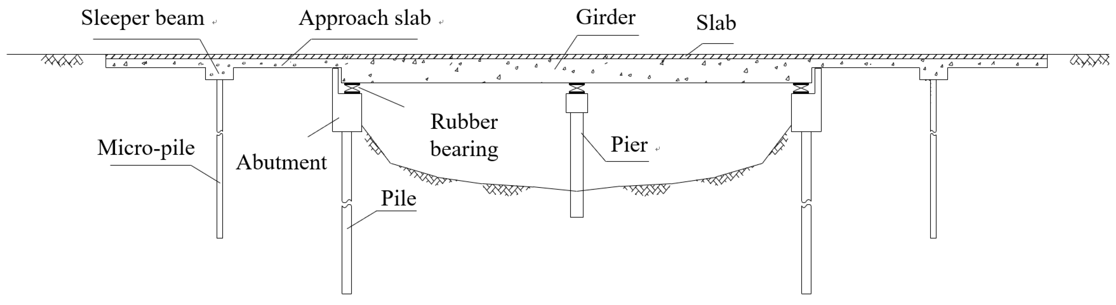
:1. Introduction
2. Experimental Program
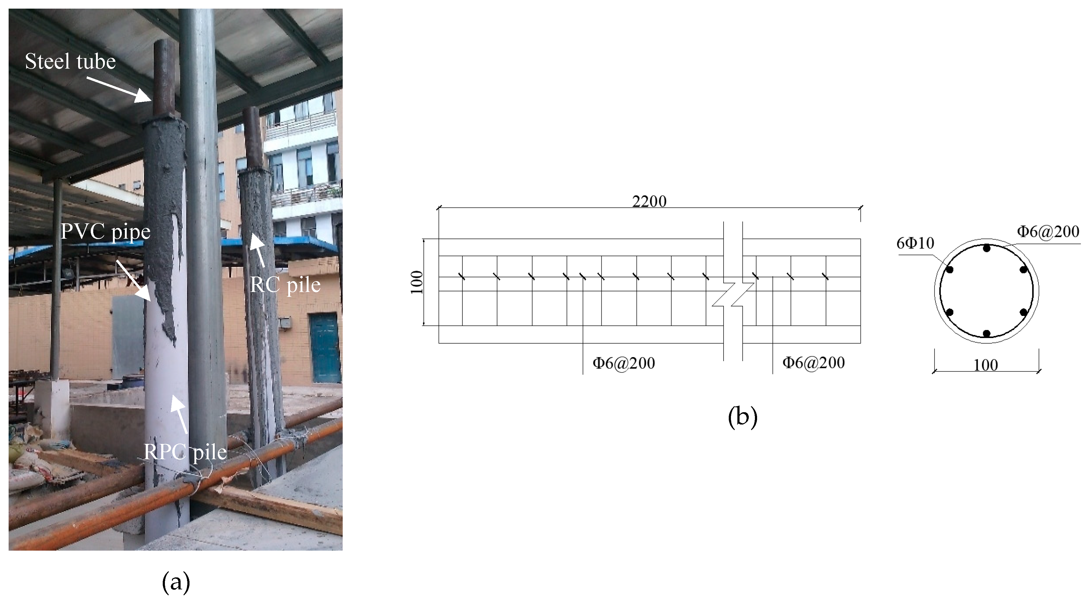
2.1. Specimen Design and Fabrication
2.2. Soil Container and Soil Parameters
2.3. Measuring Points Layout
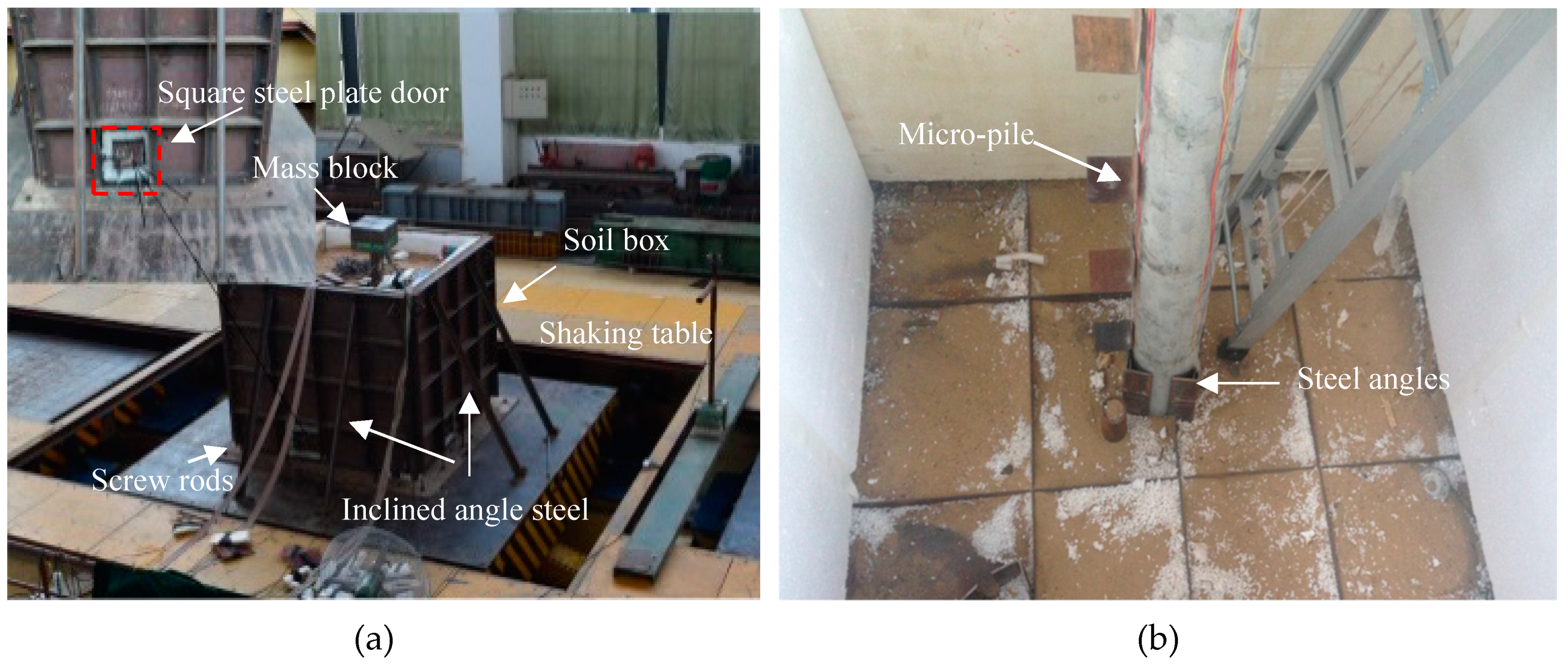
2.4. Loading Device and Scheme
3. Experimental Results
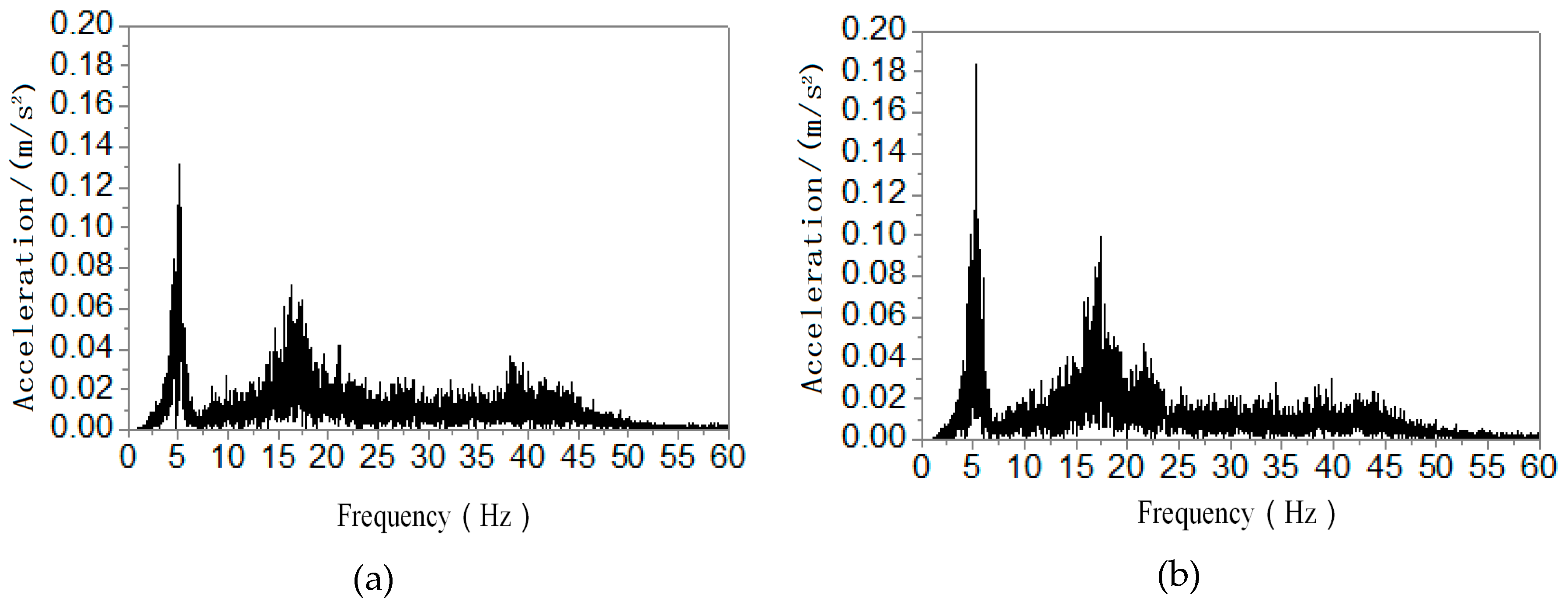
3.1. Dynamic Characteristics
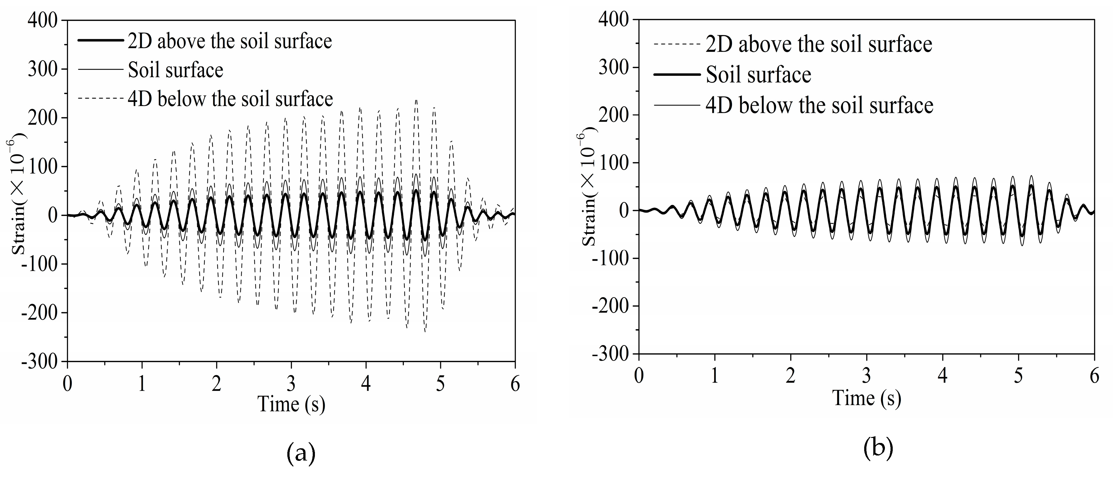
3.2. Strains Responses
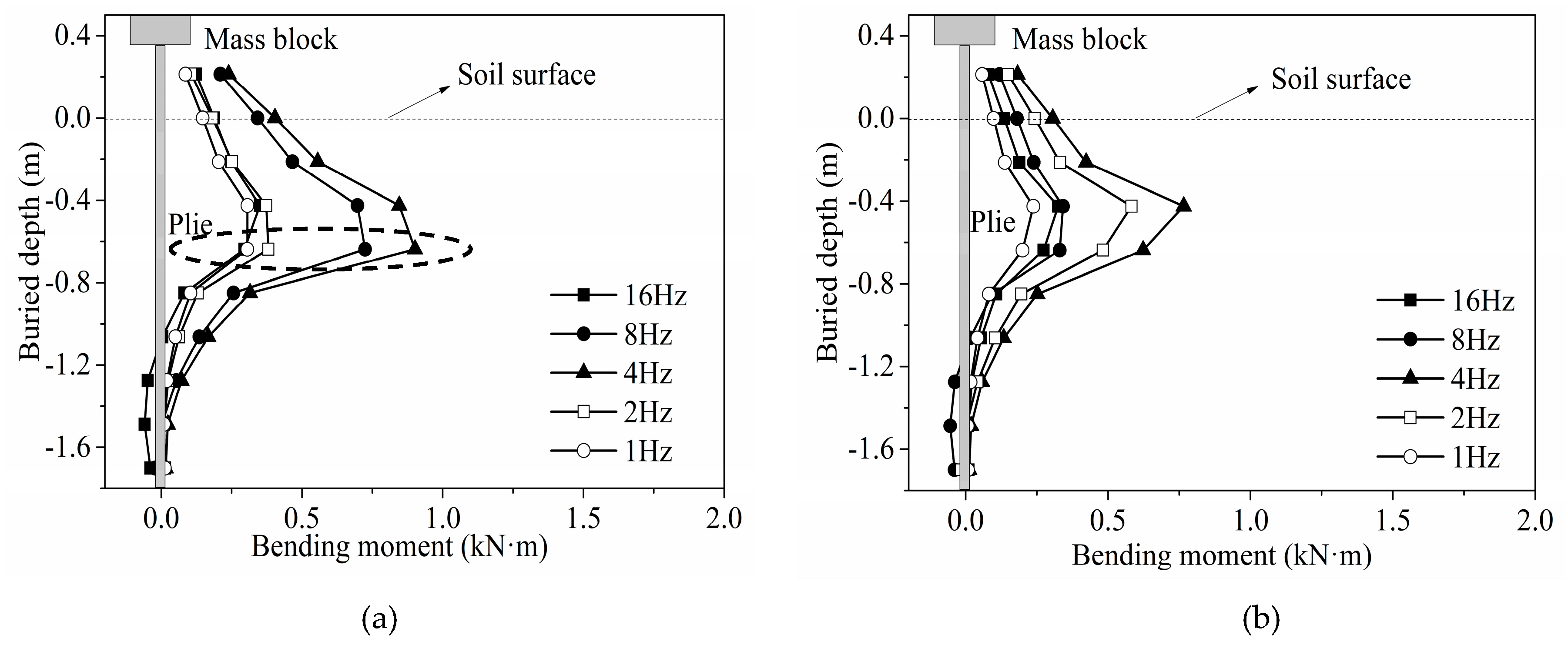
3.3. Bending Moment of Piles
3.3.1. The Influence of Frequencies
3.3.2. The Influence of Seismic Waves
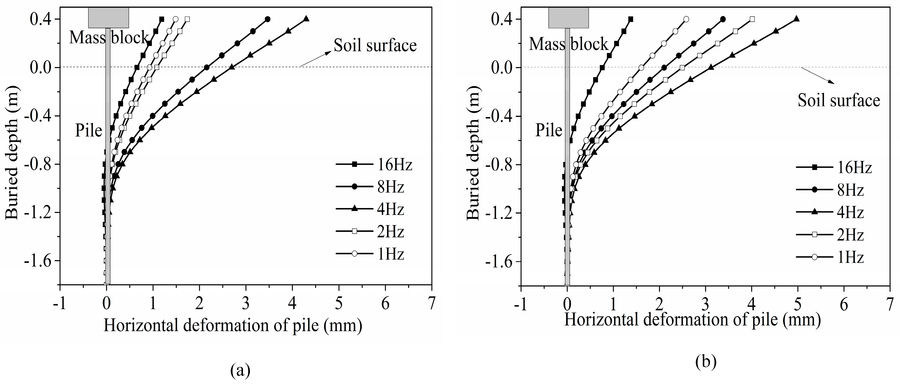
3.4. Deformation of Piles
3.4.1. The Influence of Frequencies
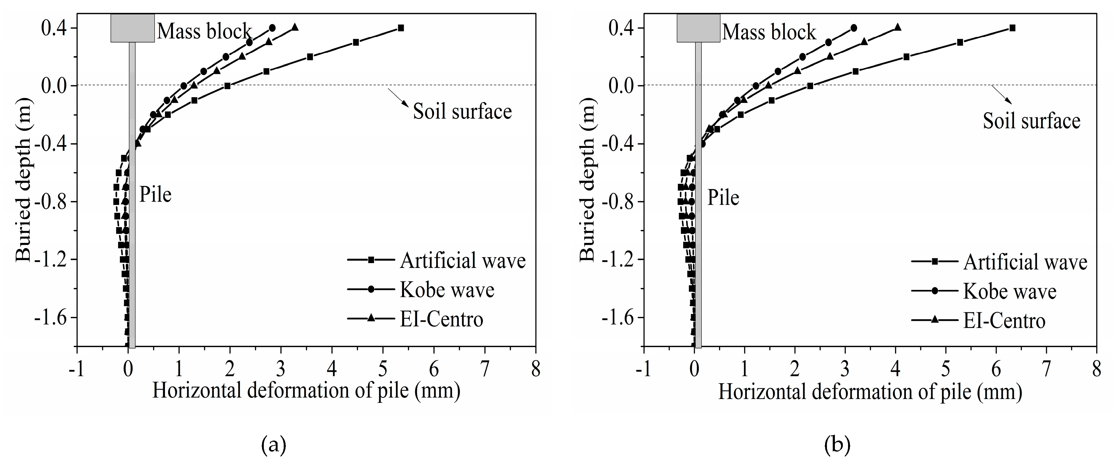
3.4.2. The Influence of Seismic Waves
4. Observations and Conclusions
- (1)
- The first and second natural frequencies of the RPC micro pile are about 4.7 Hz and 16.3 Hz, and that of RC are 3.62 Hz and 15.4 Hz, respectively. Moreover, both compactness of sand and the natural frequencies of micro piles are increased under the load of repeated white noise.
- (2)
- Compared with the action of sine waves and the action of seismic waves, the frequency of sine wave is relatively monotonous, but the frequency of the seismic wave is abundant, inducing the reverse deformation and bending moment of the pile more remarkable under the dynamic excitation load. It is also found that the dynamic response characteristics of piles under artificial wave were the most significant, which was followed by the EI-Centro wave, and then by the Kobe wave. The responses of piles under seismic wave loads are larger than those of sine waves.
- (3)
- The maximum strains of piles were observed at the depth of 4.2 D (D is the diameter of the pile). Meanwhile, the maximum bending moments of the RPC and RC pile appear at the depth of 0.64D and 0.42 D, respectively, under a dynamic excitation. The peak horizontal deformations of piles were demonstrated at the pile head.
- (4)
- Compared with the dynamic responses of the RC pile, it can be seen that the bending moments and the strain responses of RPC are larger than that of the RC pile, and the maximum increased by 40% and 98%, respectively. In addition, although the horizontal displacements of the RC pile are larger than that of the RPC pile, the increments are slight at only the range of 15%. Therefore, the RPC micro pile with steel fiber has better crack resistance, higher ductility, and flexural rigidity than that of the RC pile.
Author Contributions
Acknowledgments
Conflicts of Interest
References
- Hoppe, E.; Weakley, K.; Thompson, P. Jointless bridge design at the Virginia Department of Transportation. Transp. Res. Procedia 2016, 14, 3943–3952. [Google Scholar] [CrossRef]
- Zhao, Q.; Lin, C.; Zhao, Y. Mechanical Characteristics of a New Type of Jointless Bridge with an Arch Structure. In Proceedings of the 3rd International Conference on Smart City and Systems Engineering, Xiamen, China, 29–30 December 2018; pp. 300–307. [Google Scholar]
- Kunin, J.; Alampalli, S. Integral abutment bridges: Current practice in United States and Canada. J. Perform. Constr. Fac. 2000, 14, 104–111. [Google Scholar] [CrossRef]
- Mistry, V.C. Integral abutment and jointless bridges. In Proceedings of the FHWA Conference on Integral Abutment and Jointless Bridges, Baltimore, MD, USA, 16–18 March 2005; pp. 3–11. [Google Scholar]
- Yannotti, A.P.; Alampalli, S.; White, H.L. New York State Department of Transportation’s Experience with Integral Abutment Bridges. In Proceedings of the FHWA Conference on Integral Abutment and Jointless Bridges, Baltimore, MD, USA, 16–18 March 2005; pp. 41–49. [Google Scholar]
- Erhan, S.; Dicleli, M. Comparative assessment of the seismic performance of integral and conventional bridges with respect to the differences at the abutments. Bull. Earthq. Eng. 2015, 13, 653–677. [Google Scholar] [CrossRef]
- Wood, J.H. Earthquake Design of Bridges with Integral Abutments. In Proceedings of the 6th International Conference on Earthquake Geotechnical Engineering, Christchurch, New Zealand, 1–4 November 2015; pp. 1–8. [Google Scholar]
- Ulgen, D.; Saglam, S.; Ozkan, M.Y. Dynamic response of a flexible rectangular underground structure in sand: Centrifuge modeling. Bull. Earthq. Eng. 2015, 13, 1–20. [Google Scholar] [CrossRef]
- Lou, M.L.; Wang, W.J. Study on soil-pile-structure-TMD interaction system by shaking table model test. Earthq. Eng. Eng. Vib. 2004, 3, 127–137. [Google Scholar]
- Gu, Q.; Barbato, M.; Conte, J.P. OpenSees-SNOPT framework for finite-element-based optimization of structural and geotechnical systems. J. Struct. Eng. 2011, 138, 822–834. [Google Scholar] [CrossRef]
- Basha, H.A. Infiltration models for semi-infinite soil profiles. Water Resour. Res. 2011, 47, 1–16. [Google Scholar] [CrossRef]
- Chau, K.T.; Shen, C.Y.; Guo, X. Nonlinear seismic soil–pile–structure interactions: Shaking table tests and FEM analyses. Soil. Dyn. Earthq. Eng. 2009, 29, 300–310. [Google Scholar] [CrossRef]
- Chen, B.C.; Chen, G.D.; Lin, S.S. Trial-design study on integral abutment bridge by using UHPC-RC stage wise piles. J. Archit. Civ. Eng. 2018, 35, 1–8. [Google Scholar]
- Fu, C.; Zhuang, Y.Z.; Chen, B.C. Study on Trial Design of Jointless Bridge with Mini Pile Support Approach Slab. J. Archit. Civ. Eng. 2017, 34, 96–104. [Google Scholar]
- Chen, B.C.; Zhuang, Y.Z.; Briseghella, B. Jointless Bridges, 1st ed.; China Communication Press: Beijing, China, 2013. [Google Scholar]
- Cantoni, R.; Collotta, T.; Ghionna, V.N. A design method for reticulated micro-pile structures in sliding slopes. Ground Eng. 1989, 22, 41–45. [Google Scholar]
- Koreck, H.W. Small-Diameter Bored Injection Pile. Ground Eng. 1978, 11, 14–29. [Google Scholar]
- Amour, T.; Groneck, P.; Keeley, J. Micro Pile Design and Construction Guidelines: Implementation-Manual; Report No. FHWA-SA-97-070; U.S. Federal Highway Administration: Washington, DC, USA, 2000.
- Chen, G.X.; Chen, S.; Zuo, X.; Du, X.L. Shaking-table tests and numerical simulations on a subway structure in soft soil. Soil Dyn. Earthq. Eng. 2015, 76, 13–28. [Google Scholar]
- Fabbrocino, F.; Farina, I.; Modano, M. Loading noise effects on the system identification of composite structures by dynamic tests with vibrodyne. Compos. Part B Eng. 2017, 115, 376–383. [Google Scholar] [CrossRef]
- Lee, S.J. Behavior of a Single Micropile in Sand under Cyclic Axial Loads. Ph.D. Thesis, University of Illinois at Urbana-Champaign, Urbana, IL, USA, 2004. [Google Scholar]
- Zhuang, Y.Z.; Chen, Y.; Huang, F.Y. Experimental Study of Influence of Frequency on Micro pile-soil Interaction. World Bridges 2016, 44, 21–25. [Google Scholar]
- Wang, S.Z. Research on Dynamic Behaviors and Energy Dissipation Capacity of Micro Pile with Predrilled Oversize Hole in Semi-Integral Abutment Bridge. Master’s Thesis, Fuzhou University, Fuzhou, China, 2016. [Google Scholar]
- Zhuang, Y.Z.; Wang, S.Z.; Fan, Z.H. Test and Research on Mechanical Properties of Laterally Loaded Micro-pile with Predrilled Oversize Hole. Highway 2015, 8, 54–58. [Google Scholar]
- Makris, N.; Gazetas, G. Dynamic pile-soil-pile interaction. Part II: Lateral and seismic response. Earthq. Eng. Struct. Dyn. 1992, 21, 145–162. [Google Scholar]
- Gazetas, G.; Dobry, R. Horizontal response of piles in layered soils. J. Geotech. Eng. 1984, 110, 20–40. [Google Scholar] [CrossRef]
- National Cooperative Highway Research Program. Static and Dynamic Lateral Loading of Pile Groups; NCHRP Report461; Transportation Research Board-National Research Council: Washington, DC, USA, 2001; pp. 665–669. [Google Scholar]
- American Petroleum Institute. API Recommended Practice for Planning, Designing and Constructing Fixed Offshore Platforms, 1st ed.; American Petroleum Institute, Production Dept.: Washington, DC, USA, 1976. [Google Scholar]
- Reese, L.C. Laterally loaded piles: Program documentation. J. Geotech. Geoenviron. 1977, 103, 287–305. [Google Scholar] [CrossRef]
- Chen, B. Study on Shear Behavior of Prestressed RPC Beam. Master’s Thesis, Hunan University, Changsha, China, 2007. [Google Scholar]
- Liu, Z.Y.; Lin, H.; Jiang, X.L. Numerical analysis of pile soil interaction under pile head vertical load. J. Cent. South Univ. 2011, 42, 508–513. [Google Scholar]
- Huang, F.Y.; Qian, H.M.; Zhuang, Y.Z. Experimental Study on the Dynamic Response of PHC Pipe-Piles in Liquefiable Soil. J. Test. Eval. 2016, 45, 230–241. [Google Scholar]
- Chinese Research Institute of Highway Ministry of Transport. Test Method of Soils for Highway Engineering; JTG E40-2007; China Communications Press: Beijing, China, 2007. [Google Scholar]
- Kulhawy, F.H.; Mayne, P.W. Manual on Estimating Soil Properties for Foundation Design, 1st ed.; Electric Power Research Institute: Palo Alto, CA, USA, 1990. [Google Scholar]
- ASTM Committee D-18 on Soil and Rock. Standard Practice for Classification of Soils for Engineering Purposes (Unified Soil Classification System); ASTM international: West Conshohocken, PA, USA, 2017. [Google Scholar]
- Lou, M.L.; Wang, W.J.; Zhu, T.; Ma, H.C. Soil lateral boundary effect in shaking table Model test of soil-structure system. J. Earthq. Eng. Eng. Vib. 2000, 20, 30–36. [Google Scholar]
- Chen, W.F. Plasticity in Reinforced Concrete, 2nd ed.; J. Ross Publishing Inc.: Fort Lauderdale, FL, USA, 2007. [Google Scholar]
- Chen, G.X.; Zhuang, H.Y.; Du, X.L. Large Dynamic Interaction Vibration of Soil and Metro Station Structures. J. Earthq. Eng. Eng. Vib. 2007, 27, 171–176. [Google Scholar]
- LV, X.L.; Chen, Y.Q.; Chen, B. Shaking Table Testing of Dynamic Soil-structure Interaction System. J. Earthq. Eng. Eng. Vib. 2000, 20, 20–29. [Google Scholar]
- Chen, R.P.; Ren, Y.; Chen, Y.M. Experimental investigation on a single stiff pile subjected to long-term axial cyclic loading. Chin. J. Geotech. Eng. 2011, 33, 1926–1933. [Google Scholar]
- Huang, F.Y.; Wu, S.W.; Luo, X.Y. Pseudo-static low cycle test on the mechanical behavior of PHC pipe piles with consideration of soil-pile interaction. Eng. Struct. 2018, 171, 992–1006. [Google Scholar] [CrossRef]
- Chinese Academy of Architectural Sciences. Technical Code for Building Pile Foundation; JGJ94-2008; China Architecture & Building Press: Beijing, China, 1 October 2008. [Google Scholar]
- Prakash, S. Pile Foundations in Engineering Practice, 1st ed.; John Wiley & Sons, Inc.: Hoboken, NJ, USA, 1990. [Google Scholar]
- Ashour, M.; Norris, G.; Pilling, P. Strain wedge model capability of analyzing behavior of laterally loaded isolated piles, drilled shafts, and pile groups. J. Bridge Eng. 2002, 7, 245–254. [Google Scholar] [CrossRef]
- Xu, L. Study on Dynamic Response Features of Micro Pile Foundation Based on Shaking Table Test. Master’s Thesis, Fuzhou University, Fuzhou, China, 2017. [Google Scholar]
- Chinese Academy of Architectural Sciences. Code for Seismic Design of Buildings; GB50011-2010; China Architecture & Building Press: Beijing, China, 2010. [Google Scholar]


| Specimen | Diameter (mm) | Moment of Inertia I (×10−5 m4) | Modulus of Elasticity E (×104 MPa) | Relative Pile Length z (m) | Flexural Rigidity (kN·m2) | Section |
|---|---|---|---|---|---|---|
| RPC pile | 100 | 0.49 | 4.41 | 3.49 | 216.7 | circular |
| RC(C40) pile | 3.25 | 3.78 | 159.3 |
| Water Content ω (%) | Density ρ (g/cm3) | Void Ratio e | Cohesive Strength c (kPa) | Internal Friction Angle φ (°) | Cu | Poisson Ratio v |
|---|---|---|---|---|---|---|
| 2.2 | 1.98 | 0.80 | 4 | 32 | 3.15 | 0.3 |
| Case | Seismic Wave | Peak Acceleration (g) | Frequency (Hz) | Case | Seismic Wave | Peak Acceleration (g) | Frequency (Hz) |
|---|---|---|---|---|---|---|---|
| 1 | White noise | 5 | White noise | ||||
| Sine wave | 0.15 | 1Hz | Sine wave | 0.15 | 16 Hz | ||
| 2 | White noise | 6 | EI-Centro wave | 0.15 | |||
| Sine wave | 0.15 | 2 Hz | |||||
| 3 | White noise | 7 | Kobe wave | 0.15 | |||
| Sine wave | 0.15 | 4 Hz | |||||
| 4 | White noise | 8 | Artificial wave | 0.15 | |||
| Sine wave | 0.15 | 8 Hz |
© 2019 by the authors. Licensee MDPI, Basel, Switzerland. This article is an open access article distributed under the terms and conditions of the Creative Commons Attribution (CC BY) license (http://creativecommons.org/licenses/by/4.0/).
Share and Cite
Cheng, J.; Luo, X.; Zhuang, Y.; Xu, L.; Luo, X. Experimental Study on Dynamic Response Characteristics of RPC and RC Micro Piles in SAJBs. Appl. Sci. 2019, 9, 2644. https://doi.org/10.3390/app9132644
Cheng J, Luo X, Zhuang Y, Xu L, Luo X. Experimental Study on Dynamic Response Characteristics of RPC and RC Micro Piles in SAJBs. Applied Sciences. 2019; 9(13):2644. https://doi.org/10.3390/app9132644
Chicago/Turabian StyleCheng, Junfeng, Xiaoyong Luo, Yizhou Zhuang, Liang Xu, and Xiaoye Luo. 2019. "Experimental Study on Dynamic Response Characteristics of RPC and RC Micro Piles in SAJBs" Applied Sciences 9, no. 13: 2644. https://doi.org/10.3390/app9132644
APA StyleCheng, J., Luo, X., Zhuang, Y., Xu, L., & Luo, X. (2019). Experimental Study on Dynamic Response Characteristics of RPC and RC Micro Piles in SAJBs. Applied Sciences, 9(13), 2644. https://doi.org/10.3390/app9132644