Abstract
Dielectric electro-active polymer (DEAP) materials, also called artificial muscle, are a kind of EAP smart materials with extraordinary strains up to 30% at a high driving voltage. However, the asymmetric rate-dependent hysteresis is a barrier for trajectory tracking control of DEAP actuators. To overcome the barrier, in this paper, a Hammerstein model is established for the asymmetric rate-dependent hysteresis of a DEAP actuator first, in which a modified Prandtl-Ishlinskii (MPI) model is used to represent the static hysteresis nonlinear part, and an autoregressive with exogenous inputs (ARX) model is used to represent the linear dynamic part. Applying Levenberg-Marquardt (LM) algorithm identifies the parameters of the Hammerstein model. Then, based on the MPI model, an inverse hysteresis compensator is obtained to compensate the hysteresis behavior. Finally, a compound controller consisting of the hysteresis compensator and a novel discrete-time terminal sliding mode controller (DTSMC) without state observer is proposed to achieve the high-precision trajectory tracking control. Stability analysis of the closed-loop system is verified by using Lyapunov stability theorem. Experimental results based on a DEAP actuator show that the proposed controller has better tracking control performance compared with a conventional discrete-time sliding mode controller (DSMC).
1. Introduction
Dielectric electro-active polymer (DEAP) materials are a promising actuation technology due to the merits of lightweight, large strain, high energy density, low-noise, and fast response [1,2]. DEAP materials, as a kind of soft electroactive material, are composed of a polymer film sandwiched between two silver metal soft electrodes layers [3]. The working principle of DEAP materials is shown in Figure 1. It can be simply divided into three steps [3]: (1) a large driving voltage is applied to the silver metal soft electrodes layers to produce a high electric field; (2) the silver metal soft electrodes layers can be regarded as a flat capacitor, a Maxwell stress will be produced by electrostatic forces; (3) the polymer film is extruded under the Maxwell stress to result in actuation. Based on this basic working principle, DEAP materials have been widely applied in high-precision trajectory tracking control as actuators and achieved great potential for applications in bioinspired soft robots filed, including an arm wrestling robot [4], a flying robot [5], and a swimming robot [6]. However, like other smart materials such as shape memory alloys (SMA), piezoelectrics and magnetostrictives, the inherent asymmetric rate-dependent hysteresis nonlinearity is ubiquitous in DEAP actuators [7], which causes tracking inaccuracy, leads to a decrease in the performance of the closed-loop system, or may even result in oscillations. Therefore, the asymmetric rate-dependent hysteresis modeling and tracking control of such DEAP actuators have been important issues.
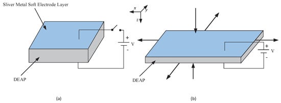
Figure 1.
The working principle of dielectric electro-active polymer (DEAP) materials. (a) Power cut: Initial state of DEAP materials. (b) Power supply: Actuation direction of DEAP materials.
The asymmetric rate-dependent hysteresis models of the smart materials can be roughly classified into three categories. The first category is physics-based hysteresis models. For instance, Ref. [8] presented a dynamic Jiles–Atherton model to describe the asymmetric rate-dependent hysteresis of giant magnetostrictive actuators (GMAs). The second category is phenomenological hysteresis models. For example, Ref. [9] proposed an MPI model to characterize the asymmetric rate-dependent hysteresis of dielectric elastomer actuators (DEAs), where dynamical envelope functions were used to describe the rate-dependent hysteresis, and polynomial operators were introduced to characterize the asymmetric . Ref. [10] proposed an MPI model to describe the asymmetric rate-dependent hysteresis of magnetostrictive actuators, in which a rate-dependent PI model was utilized to describe the rate-dependent hysteresis, and dead-zone operators were introduced to characterize the asymmetric. The third category is the intelligent methods-based hysteresis models. Ref. [11] developed a nonlinear ARX recurrent neural network hysteresis model to characterize the asymmetric rate-dependent hysteresis of SMA actuators. Refs. [7,12] developed a Preisach-type dynamic nonlinear ARX fuzzy hysteresis model to describe the asymmetric rate-dependent hysteresis of DEAP actuators. It should be pointed out that the unmodeled hysteresis nonlinearity, residual dynamics, parameter uncertainties and external disturbances will reduce the trajectory tracking accuracy. Therefore, it is necessary to design a robust controller to deal with the nonlinear disturbances.
Various control strategies have been developed for trajectory tracking control of DEAP actuators such as PID control [7,13], internal model control [14] and adaptive sliding mode control (SMC) [15]. Among those control strategies, SMC scheme has been widely used to control the hysteresis nonlinearity systems, because SMC scheme can guarantee the global robustness of the systems, and can simply and effectively cope with parameters variation and external disturbances [16]. However, the conventional SMC scheme can only make the system states converge to the equilibrium point asymptotically with infinite settling time. To overcome the shortcoming, terminal sliding mode controller (TSMC) scheme was proposed [17], in which a nonlinear switching surface was employed to achieve finite time convergence [18]. In the literature, Ref. [19] developed a TSMC scheme for precision tracking control and finite time convergence of a piezoelectric-driven micropositioning system. Ref. [20] proposed an adaptive-gain fast nonsingular TSMC scheme for a piezo positing stage system which can quickly converge in finite time and reduce chattering. The aforementioned SMC and TSMC schemes are all applied in continuous-time domain; however, with the wide use of computers in control systems, the DSMC theory [21] has attracted considerable attention in recent years [22,23,24]. It must be pointed out that the continuous-time SMC cannot directly convert into its discrete counterpart through simple equivalence. DSMC and DTSMC schemes have been successfully applied to other smart actuators. For instance, Ref. [25] proposed a novel DSMC scheme for precision tracking control of a piezoelectric actuator. In addition, for making the system state converge to the equilibrium point asymptotically within finite steps, Refs. [26,27] proposed DTSMC schemes for precision tracking control of piezoelectric actuators, and the stability of the control systems and the effectiveness of the proposed control schemes were demonstrated through experimental studies. However, to the knowledge of the author, DTSMC scheme has not been applied for precision trajectory tracking of DEAP actuators in the literature.
This paper focuses on the asymmetric rate-dependent hysteresis modeling and trajectory tracking control of a DEAP actuator under different input frequencies. A Hammerstein model with hysteresis nonlinearity is established to describe the asymmetric rate-dependent hysteresis of the DEAP actuator. To estimate the parameters of the model, LM algorithm [28,29] is utilized. Based on the MPI model, an inverse hysteresis compensator is obtained to suppress the asymmetric hysteresis. In order to achieve precision tracking control and robustness of the closed-loop system, a DTSMC with a new discrete-time terminal sliding function is proposed. The main contributions of this paper are summarized as follows:
(1) A Hammerstein model with hysteresis nonlinearity is established to account the asymmetric rate-dependent hysteresis of the DEAP actuator and the lumped nonlinear disturbance term is well formulated. It provides with a detailed model for the closed-loop system.
(2) A DTSMC scheme based on a new discrete-time terminal sliding function is first proposed for the DEAP actuator. The proposed control scheme not only improves the trajectory tracking control accuracy and error convergence but also suppresses the chattering phenomenon. In addition, the proposed control scheme does not require a state observer.
(3) Compared with other DTSMC schemes, a terminal-sliding-mode-type switching control law is defined in the proposed DTSMC scheme, which improves the robustness feature of the closed-loop system in the presence of unmodeled hysteresis nonlinearity, residual dynamics, parameter uncertainties and external disturbances.
(4) Finite steps convergence and stability of the closed-loop system are theoretically verified and an experimental investigation is conducted to validate the effectiveness of the proposed control scheme to the DEAP actuator. Then, a comparison between the proposed control scheme and the DSMC scheme is undertaken.
The remainder of the paper is organized as follows. In Section 2, the analytical formulation of the Hammerstein model and the inverse MPI model are established first, and then the parameters of the Hammerstein model are identified by LM algorithm. In Section 3, a compound controller is proposed, and the system stability is proved. Experimental results of the proposed controller to the DEAP actuator are presented in Section 4. Conclusions are given in Section 5.
2. Hammerstein Model for DEAP Actuator
In this section, in order to characterize asymmetric hysteresis loops of the DEAP actuator, a Hammerstein model is established, as shown in Figure 2. It consists of two parts: nonlinear static part and linear dynamic part. The nonlinear static part is represented by an MPI model to describe the asymmetric hysteresis, and the linear dynamic part is represented by an ARX model to describe the rate-dependent hysteresis. In the Figure 2, and represent the input and output of the DEAP actuator, respectively, is the corresponding unmeasurable internal variable, and is the external disturbance.
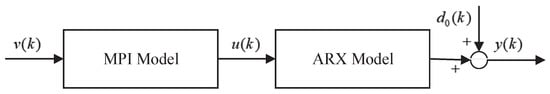
Figure 2.
Hammerstein model for DEAP actuator.
2.1. MPI Model
In this subsection, an MPI model is established to characterize the asymmetric hysteresis of the DEAP actuator. The MPI model is formulated as the cascade of the PI model and the dead-zone (DZ) model [30], in which the PI model is a weighted superposition of play operators, and the DZ model is a weighted superposition of dead-zone operators. The play operator and the dead-zone operator are shown in Figure 3 and Figure 4, respectively.
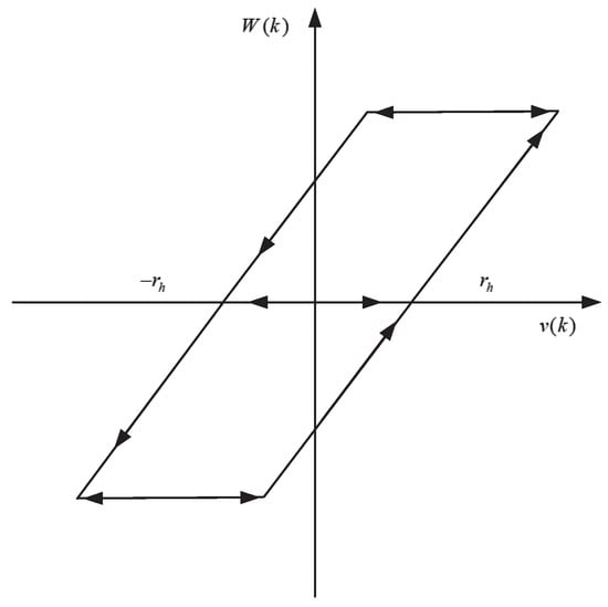
Figure 3.
The play operator.
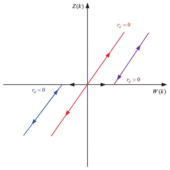
Figure 4.
The one side dead-zone operator.
The play operator is expressed as [31]
while the initial condition is defined as follows:
The output of the PI model can be formulated as
where q is a given positive constant; v and W represent the input and output of the PI model, respectively; is the vector of weights; is the vector of thresholds with ; denotes the vector of play operators; is the vector of initial states; n is the number of play operators.
The formulation of the dead-zone operator is expressed as
The output of the DZ model can be formulated as
where W and Z denote the input and output of the DZ model, respectively; is the vector of weights; is the vector of thresholds with ; m is the number of dead-zone operators.
Substituting Equations (3) into (5), the mathematical formulation of the MPI model can be derived as
The form of the inverse MPI model is the same as the MPI model. From Equation (6), the inverse MPI model can be expressed as [31]
where is a positive constant; is the vector of inverse play operators; is the intinal state; and denote the weighting vector and the threshold vector of inverse play operators, respectively; is the vector of inverse dead-zone operators; and denote the weighting vector and the threshold vector of inverse dead-zone operators, respectively.
Here
and
2.2. ARX Model
In this subsection, a linear dynamic ARX model is established to characterize the rate-dependent hysteresis of the DEAP actuator, which can be defined as
where and are polynomials in the unit backward shift operator with the known orders and ; is the system output sequence; is the input of the ARX model and also the output of the MPI model; is the external disturbance.
Define the parameter vectors , and . Define the information vectors , and .
Equation (10) can be turned into
2.3. Parameters Identification
The goal of this subsection is to obtain the parameters values of the MPI model and the ARX model. Specific identification steps are as follows:
Step (1): The asymmetric hysteresis characterization of the DEAP actuator is modeled by using the MPI model. A low frequency input signal v of Hz is given to the DEAP actuator, and N pairs of discrete input and output sequences are measured. Then, based on the input data v and the output data y, LM algorithm is employed to identify the MPI model parameters.
Step (2): After the MPI model is determined, a hybrid frequency input signal in range of to Hz is given to the DEAP actuator, and the discrete input and output sequences are measured. Based on the identified MPI model and v, the intermediate unmeasurable variable u can be obtained. Then, based on the intermediate variable u and the output data y, the parameters of the ARX model are identified by LM algorithm.
The accuracy of the identified model can be expressed by root-mean-square error (RMSE) and mean absolute error (MAE), which are defined as follows:
where is the output of the DEAP actuator, is the output of the Hammerstein model, and N is the amount of experimental data. The identified parameters of the PI model, DZ model and ARX model are given in Table 1, Table 2 and Table 3, respectively. Figure 5 shows the asymmetric rate-dependent hysteresis loops of the DEAP actuator in the range of to Hz. It illustrates that the width of the hysteresis loops will gradually increase with increasing frequency of the input signal [7,12].

Table 1.
The identified weighting vectors of the Prandtl-Ishlinskii (PI) model.
Table 2.
The identified weighting vectors of the dead-zone (DZ) model.
Table 3.
The identified parameters of the autoregressive with exogenous inputs (ARX) model.
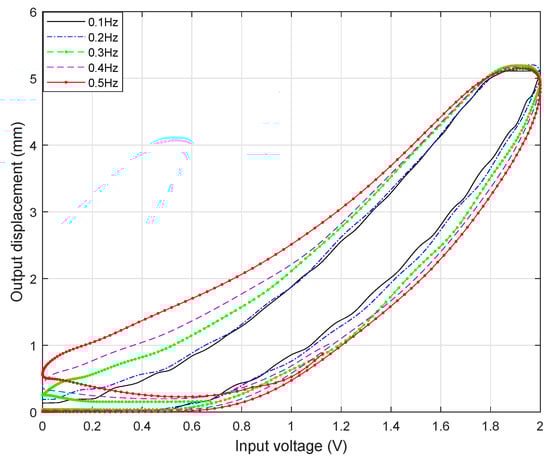
Figure 5.
The rate-dependent hysteresis loops of the DEAP actuator.
2.4. Model Validation
To validate the Hammerstein model for the DEAP actuator, input signals at a frequency of Hz, Hz, Hz, Hz, Hz, and a hybrid frequency in range of to Hz are applied to the DEAP actuator, respectively. Figure 6 shows the input-output relationship between the Hammerstein model and the DEAP actuator under different input frequencies. Table 4 shows the modeling errors. It can be seen that the maximal RMSE and maximal MAE are mm and mm, respectively. Therefore, the identified parameters of the Hammerstein model are correct, and the Hammerstein model is effective in characterizing asymmetric rate-dependent hysteresis of the DEAP actuator.
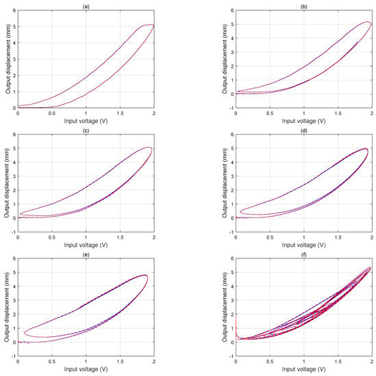
Figure 6.
The hysteresis loops of the Hammerstein model under different frequencies. (a) 0.1 Hz. (b) 0.2 Hz. (c) 0.3 Hz. (d) 0.4 Hz. (e) 0.5 Hz. (f) 0.1/0.2/0.3/0.4/0.5 Hz. Red dotted line: output of the Hammerstein model. Blue solid line: output of the DEAP actuator.
Table 4.
The modeling errors of the Hammerstein model under different frequencies.
3. Compound Controller Design
In this section, a compound controller is developed for the high-precision trajectory tracking control of the DEAP actuator, as shown in Figure 7. It consists of a feedforward hysteresis compensator and a feedback controller. The inverse MPI model is used to be the hysteresis compensator to offset the hysteresis behavior. A novel DTSMC is proposed to be the feedback controller to improve the trajectory tracking precision and maintain the system stability in the presence of unmodeled hysteresis nonlinearity, inverse compensation errors, residual dynamics, parameter uncertainties and external disturbances.
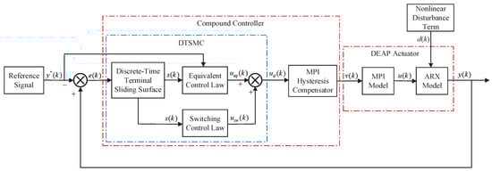
Figure 7.
The structure of the compound controller.
3.1. Design of the Novel DTSMC
In this subsection, the nonlinear disturbance term is considered, which describes the lumped effect of unmodeled hysteresis nonlinearity, inverse compensation errors, residual dynamics, parameter uncertainties and external disturbances. In order to design the proposed controller, Equation (11) is rewritten as follows:
Assumption 1.
The nonlinear disturbance term is assumed to be unknown but bounded, which can be expressed as follows:
where is a known positive constant.
Assumption 2.
The change rate of the nonlinear disturbance term is assumed to be unknown but bounded, which can be expressed as follows:
where T is the sampling period, , and δ is a known positive constant.
As reported in [32], the nonlinear disturbance term possesses the following property.
Property 1.
, , and .
In order to complete the controller design and its stability analysis, a controllable canonical representation can be obtained according to the discrete-time plant model (14)
in which
The control objective is to make the system output track a desired displacement in the presence of the nonlinear disturbance . To achieve this objective, a novel DTSMC is presented in this subsection. First, the nonlinear disturbance is estimated. Then, the DTSMC is designed based on a new discrete-time terminal sliding function and a terminal-sliding-model-type reaching law.
Remark 1.
In order to obtain the nonlinear disturbance term , the technique of perturbation estimation [33] is employed under the Assumption 1, the nonlinear disturbance term is estimated by its one-step delayed value, which can be expressed as
The state-space model (17) can be rewritten as follows:
where is the nonlinear disturbance estimation error, it can be further expressed as
Define
as the trajectory tracking error of the DEAP actuator, where is the desired displacement, is the actual displacement. Based on the trajectory tracking error, a discrete-time terminal sliding function is proposed as
where and are positive constants. The notation , denotes a ratio of two odd integers p and q, where . The design of will produce a steeper slope of the sliding surface when the system states are close to the origin, and it results in a faster convergence speed [34].
In this work, the DTSMC is designed based on equivalent control, the following reaching law is used
Based on the nominal model, the equivalent control input can be derived as follows:
It must be pointed out that the equivalent control law is derived based on the assumptions that the initial state is on the sliding surface and the estimation error . However, in practice, the above assumptions are almost non-existent. Therefore, in order to deal with the problem, defining a terminal-sliding-model-type switching control law as
where , , with .
Combining the equivalent control law (27) and the switching control law (28) can obtain the overall control law
Based on the proposed overall control law (29), the expression of becomes
Remark 2.
In order to alleviate the chattering phenomenon which may be induced by the , we employ the smoother saturation function to replace the in this work,
where the parameter σ ensures the band width of the sliding mode function . In practice, the trial-and-error method is usually employed to obtain the parameter σ and make a compromise between the chattering phenomenon and the tracking accuracy.
Remark 3.
The switching control law can drive the sliding mode dynamics into the DTSM domain with the band width of and enhance the robustness feature in the presence of the estimation error and other perturbations. In addition, and other perturbations can be tolerated by selecting suitable control gains and .
Remark 4.
The proposed DTSM control law can accelerate the convergence rate of tracking error by adding the non-linear term to the discrete-time terminal sliding function . In addition, it can be observed from Equation (29) that the designed DTSMC only needs the system output information , that is to say, the state observer is not needed.
3.2. Stability Analysis
In order to analyze the stability of the closed-loop system with the proposed DTSMC, the following assumption condition about the discrete-time terminal sliding surface is required.
Assumption 3.
There is a positive constant ϵ such that and .
During the stability analysis, the following proposition is needed.
Proposition 1.
.
The proof of the proposition can be seen in the Appendix A.
Theorem 1.
Considering the state-space model (17) along with the discrete-time terminal sliding surface (22) and Assumption 3, if we employ the DTSM control law (29), the following sliding mode dynamics can be guaranteed.
(1) The discrete-time sliding mode dynamics from any initial state will enter the region Δ within steps, where
where the operator gives the nearest integer that is less than or equal to the original value.
For any and , the following relationships are met [35]:
(2) Once the sliding mode dynamics enter the region Δ, it will never escape in the subsequent time.
Proof of Theorem 1.
(1) Define a discrete-time Lyapunov function , it can be obtained that
In this work, we consider the following two cases if .
Case 1: Consider , we can obtain that
By Proposition 1 and Assumption 3 , Equation (36) can be deduced as
Referring to , the one-step forward sliding function , it can be obtained that
then
Hence, if , holds.
Case 2: Consider with Assumption 3 and Proposition 1, the proof procedure of is similar to that of the Case 1.
According to the analysis results of Case 1 and Case 2 when , it can be derived from Equation (40) that . We can directly solve to obtain the solution defined in Equation (33). Hence, existing results in .
(2) Next, we will divide two cases to prove that once the sliding mode state . Define , we can obtain .
By Equation (31), it can be obtained that
Case 1: The proof of with .
When , Equation (41) becomes
If , by Proposition 1 and Assumption 3, it can be derived from Equation (42) as
Otherwise, when , utilizing Proposition 1 and Assumption 3, Equation (42) can be deduced as
Next, the proof of with .
Similarly, if , by Proposition 1 and Assumption 3, it can be derived from Equation (42) as
Otherwise, when , utilizing Proposition 1 and Assumption 3, Equation (42) can be deduced as
Until now, we have proved that with .
Case 2: The proof of with .
When , Equation (41) becomes
If , by Proposition 1 and Assumption 3, it can be derived from Equation (47) as
Otherwise, when , utilizing Proposition 1 and Assumption 3, Equation (47) can be deduced as
Next, the proof of with .
Similarly, if , by Proposition 1 and Assumption 3, it can be derived from Equation (47) as
Otherwise, when , utilizing Proposition 1 and Assumption 3, Equation (47) can be deduced as
To this end, we have completed the proof of with . That is to say, the sliding mode state will enter the region within steps and stay in the DTSM domain thereafter by using the proposed DTSM control law. □
4. Experimental Results and Discussion
4.1. Experimental Setup
In order to verify the effectiveness of the proposed DTSMC, the controller is deployed on the DEAP actuator for the high-precision trajectory tracking control. The block diagram and the experimental platform of the DEAP actuator are shown in Figure 8 and Figure 9, respectively. The actuator is manufactured by Danfoss PolyPower A/S Inc. Because DEAP materials are flexible materials, the DEAP actuator needs to be suspended vertically in the experimental platform to generate a certain pre-tension force. Considering the real time executions and the simplicity of the controllers development, a personal computer running Windows 10 operating system and Matlab 2017a software is employed. A high resolution split LVDT displacement sensor is utilized to measure the output displacement of the DEAP actuator. Considering the driving voltage of DEAP materials is 0–2500 V, a high voltage source S15-3P is employed. For realizing the data interaction between MATLAB 2017a and the DEAP actuator, a data acquisition card PCI-1710 is used. In this work, the sampling time T is set to s, and a white Gaussian noise is added to the controller as the external disturbance.
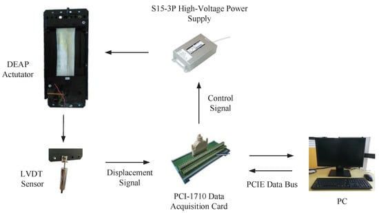
Figure 8.
Block diagram of the DEAP actuator.
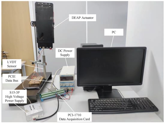
Figure 9.
Experimental platform of the DEAP actuator.
4.2. Experimental Results
In this subsection, the proposed DTSMC is tested for the high-precision trajectory tracking control of the DEAP actuator. First, we select the optimal control parameters of the proposed controller. If is fixed, a lager can guarantee a better performance. In addition, if choosing which implies and , we can obtain the smallest boundary of the final sliding mode motion. Disturbances can be well suppressed with the increasing of and ; however, the chattering phenomenon will be also increased in the control signal. Through trial and error, the selected optimal control parameters are presented in Table 5.
Table 5.
The control parameters of different controllers.
This work employs the real experimental data to verify the effectiveness of the proposed controller. For comparison, the conventional DSMC with the hysteresis compensator is employed. The control parameters of the DSMC are the same as those of the proposed controller, which are presented in Table 5.
During experimental studies, different frequencies’ input signals are generated by S15-3P and applied to drive the DEAP actuator. The corresponding tracking results of the DEAP actuator are shown in Figure 10, Figure 11, Figure 12, Figure 13, Figure 14 and Figure 15.
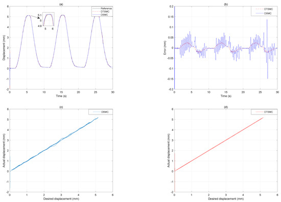
Figure 10.
The tracking results under 0.1 Hz input signal. (a) Displacement output. (b) Tracking error. (c) Desired displacement versus actual displacement of the DSMC. (d) Desired displacement versus actual displacement of the DTSMC.
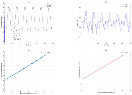
Figure 11.
The tracking results under 0.2 Hz input signal. (a) Displacement output. (b) Tracking error. (c) Desired displacement versus actual displacement of the DSMC. (d) Desired displacement versus actual displacement of the DTSMC.
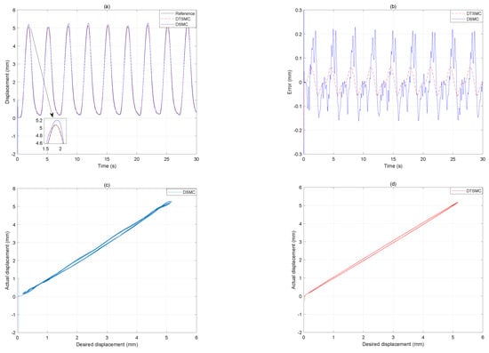
Figure 12.
The tracking results under 0.3 Hz input signal. (a) Displacement output. (b) Tracking error. (c) Desired displacement versus actual displacement of the DSMC. (d) Desired displacement versus actual displacement of the DTSMC.
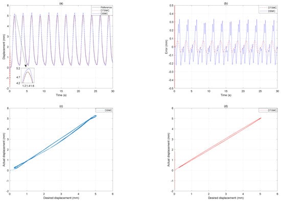
Figure 13.
The tracking results under 0.4 Hz input signal. (a) Displacement output. (b) Tracking error. (c) Desired displacement versus actual displacement of the DSMC. (d) Desired displacement versus actual displacement of the DTSMC.
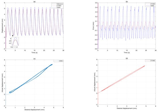
Figure 14.
The tracking results under 0.5 Hz input signal. (a) Displacement output. (b) Tracking error. (c) Desired displacement versus actual displacement of the DSMC. (d) Desired displacement versus actual displacement of the DTSMC.

Figure 15.
The tracking results under the hybrid frequency input signal. (a) Displacement output. (b) Tracking error. (c) Desired displacement versus actual displacement of the DSMC. (d) Desired displacement versus actual displacement of the DTSMC.
The desired displacement has a frequency of 0.1 Hz, the tracking results of the DSMC and the proposed DTSMC are depicted in Figure 10. The RMSE of the DSMC is mm, and the MAE is mm. In contrast, for the proposed DTSMC, the RMSE is mm, and the MAE is mm. Compared with the DSMC, the proposed DTSMC reduces the RMSE and MAE by and . In addition, from Figure 10c,d, one can see that the hysteresis phenomenon has been substantially compensated by the DTSMC, and the DSMC can also basically compensate the hysteresis phenomenon at a low frequency of Hz.
In Figure 11, the desired displacement has a frequency of 0.2 Hz. The RMSE of the DSMC is mm, and the MAE is mm. In contrast, for the proposed DTSMC, the RMSE is mm, and the MAE is mm. Compared with the DSMC, the proposed DTSMC reduces the RMSE and MAE by and . In addition, compared with the desired displacement of Hz, the proposed DTSMC increases the RMSE and MAE by and . However, the DSMC increases the RMSE and MAE by and , which are all obviously larger than those of the proposed DTSMC. Furthermore, from the Figure 12, Figure 13 and Figure 14, it can be seen that the hysteresis compensations of the proposed DTSMC gradually exceeds those of the DSMC with increasing frequency of the input signal. For more detail trajectory tracking-error results, see the computational results in Table 6. In addition, the overshoots of the DSMC at the turning points are significantly larger than those of the proposed DTSMC. Therefore, it can be concluded that the proposed DTSMC can improve the tracking control accuracy of the DEAP actuator with increasing frequency to Hz.
Table 6.
The tracking-error results of the DSMC and DTSMC controllers at different frequencies.
In order to further demonstrate the effectiveness of the proposed DTSMC, a hybrid frequency input signal in range of to Hz is used to be the desired displacement, the tracking results of the two controllers are shown in Figure 15. Table 6 gives the computational results of two indices. It can be seen that the RMSE and MAE of the proposed DTSMC is mm and mm, respectively. In contrast, the RMSE and MAE of the DSMC is mm and mm, respectively. As compared with the DSMC, the proposed DTSMC considerably reduces the RMSE and MAE by and . From Figure 15c,d, one can see that the hysteresis compensation of the proposed DTSMC is more obvious than that of the DSMC. Therefore, the proposed DTSMC has better performance than the DSMC in following a hybrid frequency input signal.
4.3. Discussion
In this paper, we propose a compound controller for the high-precision trajectory tracking control of the DEAP actuator. It consists of a feedforward hysteresis compensator (i.e., the inverse MPI model) and a feedback controller (i.e., the novel DTSMC). In order to achieve the high-precision trajectory tracking control, the inverse MPI model is first applied to compensate the hysteresis of the DEAP actuator, and then the proposed DTSMC is employed to overcome the estimation error and other perturbations. From Figure 10 and Table 6, it can be seen that the DSMC and the proposed DTSMC can achieve good tracking control when the input signal frequency is Hz, that is to say, the hysteresis characteristic is well compensated, and the estimation error and other perturbations are well overcome. From Figure 11, Figure 12, Figure 13, Figure 14 and Figure 15, and Table 6, one can see that, whether the input signal is a high frequency or a hybrid frequency, the proposed DTSMC can always achieve excellent tracking control performances. In contrast, the tracking errors of the DSMC will be significantly increased with increasing input signal frequency, and it has large overshoots at the turning points. To summarize, the proposed DTSMC is effective for the high-precision trajectory tracking control of the DEAP actuator. It provides faster error convergence, more precise trajectory tracking control, less chattering and better robustness than the DSMC. However, it should be pointed out that the nonlinear disturbance term upper bound and its change rate need to be known in the design process of the DTSMC, which are difficult to achieve in practice. In future work, we will try to apply the adaptive technology to completely compensate the uncertainty of unknown upper bound. Another possible research topic of this work may be the design of an adaptive discrete-time terminal sliding mode control without a inverse hysteresis compensator to simplify the design process of the controller and optimize the controller performance.
5. Conclusions
The inherit asymmetric rate-dependent hysteresis characterization in the DEAP actuator is a barrier to achieving high-precision trajectory tracking control. In this paper, we establish a Hammerstein model to characterize the asymmetric rate-dependent hysteresis and employ LM algorithm to identify the parameters of the MPI model and the ARX model. In order to suppress the asymmetric hysteresis behavior, the inverse MPI model is used to be the hysteresis feedforward compensator. Furthermore, to overcome the challenge of the estimation error and other perturbations, based on the hysteresis feedforward compensator, a novel DTSMC is proposed for the high-precision tracking control of the DEAP actuator, and the system stability is analyzed. A conventional DSMC with the hysteresis compensator is implemented for comparison.
The above two control schemes are tested under different frequencies’ input signals, including Hz, Hz, Hz, Hz, Hz and a hybrid frequency. Noting that, in the DSMC and DTSMC schemes, the switching control may make the chattering occur. To eliminate the chattering, we employ the smoother saturation function to replace the signum function in this work. When the input signal frequency is increased, or the input signal is a hybrid frequency, compared with the DSMC with hysteresis compensator, experimental results show that the proposed DTSMC with the hysteresis compensator can improve the tracking accuracy, robustness, and error convergence of the DEAP actuator. The hysteresis compensation effect of the proposed control scheme is significantly higher than that of the DSMC scheme.
Author Contributions
M.L. proposed the controller and wrote the manuscript. M.L. and Z.J. designed experimental and analyzed the results. Y.L. and Q.W. provided some improvement strategies to improve the accuracy of the model and helped verify the effectiveness of the control strategy. M.L. and Y.L. revised and edited the paper.
Funding
This research was funded by the National Science Foundation of China (61472037, 61375100).
Conflicts of Interest
All authors declare that there is no conflict of interest
Appendix A
The proof of the Proposition 1:
If , then , . Because , , , , . It can be obtained that .
If , then , ,, , , , , . It can be obtained that .
Hence, based on the above formulas, we can obtain that .
References
- Benslimane, M.Y.; Kiil, H.E.; Tryson, M.J. Dielectric electro-active polymer push actuators: Performance and challenges. Polym. Int. 2010, 59, 415–421. [Google Scholar] [CrossRef]
- Gu, G.Y.; Zhu, J.; Zhu, L.M.; Zhu, X. A survey on dielectric elastomer actuators for soft robots. Bioinspir. Biomim. 2017, 12, 011003. [Google Scholar] [CrossRef] [PubMed]
- Iskandarani, Y.; Karimi, H.R. Dynamic characterization for the dielectric electroactive polymer fundamental sheet. Int. J. Adv. Manuf. Technol. 2013, 66, 1457–1466. [Google Scholar] [CrossRef][Green Version]
- Kovacs, G.; Lochmatter, P.; Wissler, M. An arm wrestling robot driven by dielectric elastomer actuators. Smart Mater. Struct. 2007, 16, S306. [Google Scholar] [CrossRef]
- Shintake, J.; Rosset, S.; Schubert, B.E.; Floreano, D.; Shea, H.R. A foldable antagonistic actuator. IEEE/ASME Trans. Mechatron. 2015, 20, 1997–2008. [Google Scholar] [CrossRef]
- Godaba, H.; Li, J.; Wang, Y.; Zhu, J. A soft jellyfish robot driven by a dielectric elastomer actuator. IEEE Robot. Autom. Lett. 2016, 1, 624–631. [Google Scholar] [CrossRef]
- Truong, B.N.M.; Ahn, K.K. Inverse modeling and control of a dielectric electro-active polymer smart actuator. Sens. Actuators A Phys. 2015, 229, 118–127. [Google Scholar] [CrossRef]
- Liu, Y.; Gao, X.; Li, Y. Giant magnetostrictive actuator nonlinear dynamic Jiles–Atherton model. Sens. Actuators A Phys. 2016, 250, 7–14. [Google Scholar] [CrossRef]
- Zou, J.; Gu, G. Modeling the viscoelastic hysteresis of dielectric elastomer actuators with a modified rate-dependent prandtl–ishlinskii model. Polymers 2018, 10, 525. [Google Scholar] [CrossRef]
- Al Janaideh, M.; Aljanaideh, O. Further results on open-loop compensation of rate-dependent hysteresis in a magnetostrictive actuator with the Prandtl-Ishlinskii model. Mech. Syst. Signal Process. 2018, 104, 835–850. [Google Scholar] [CrossRef]
- Wang, H.; Song, G. Innovative NARX recurrent neural network model for ultra-thin shape memory alloy wire. Neurocomputing 2014, 134, 289–295. [Google Scholar] [CrossRef]
- Truong, B.N.M.; Ahn, K.K. Modeling, control and experimental investigation of time-average flow rate of a DEAP actuator based diaphragm pump. Int. J. Precis. Eng. Manuf. 2017, 18, 1119–1129. [Google Scholar] [CrossRef]
- Rizzello, G.; Naso, D.; York, A.; Seelecke, S. Modeling, identification, and control of a dielectric electro-active polymer positioning system. IEEE Trans. Control Syst. Technol. 2015, 23, 632–643. [Google Scholar] [CrossRef]
- Jones, R.W.; Sarban, R. Inverse grey-box model-based control of a dielectric elastomer actuator. Smart Mater. Struct. 2012, 21, 075019. [Google Scholar] [CrossRef]
- Hoffstadt, T.; Maas, J. Adaptive sliding-mode position control for dielectric elastomer actuators. IEEE/ASME Trans. Mechatron. 2017, 22, 2241–2251. [Google Scholar] [CrossRef]
- Qian, J.; Ji, C.; Pan, N.; Wu, J. Improved sliding mode control for permanent magnet synchronous motor speed regulation system. Appl. Sci. 2018, 8, 2491. [Google Scholar] [CrossRef]
- Zhihong, M.; Yu, X.H. Terminal sliding mode control of MIMO linear systems. IEEE Conf. Decis. Control 1996, 4, 4619–4624. [Google Scholar]
- Vo, A.T.; Kang, H.J. An adaptive neural non-singular fast-terminal sliding-mode control for industrial robotic manipulators. Appl. Sci. 2018, 8, 2562. [Google Scholar] [CrossRef]
- Wang, G.; Xu, Q. Adaptive terminal sliding mode control for motion tracking of a micropositioning system. Asian J. Control 2018, 20, 1241–1252. [Google Scholar] [CrossRef]
- Dinh, T.X.; Ahn, K.K. Adaptive-gain fast nonsingular terminal sliding mode for position control of a piezo positioning stage. Proc. Inst. Mech. Eng. Part I J. Syst. Control Eng. 2018, 232, 994–1014. [Google Scholar] [CrossRef]
- Furuta, K. Sliding mode control of a discrete system. Syst. Control Lett. 1990, 14, 145–152. [Google Scholar] [CrossRef]
- Chakrabarty, S.; Bandyopadhyay, B. A generalized reaching law for discrete time sliding mode control. Automatica 2015, 52, 83–86. [Google Scholar] [CrossRef]
- Nguyen, M.L.; Chen, X.; Yang, F. Discrete-time quasi-sliding-mode control with prescribed performance function and its application to piezo-actuated positioning systems. IEEE Trans. Ind. Electron. 2018, 65, 942–950. [Google Scholar] [CrossRef]
- Huber, O.; Acary, V.; Brogliato, B. Lyapunov stability and performance analysis of the implicit discrete sliding mode control. IEEE Trans. Autom. Control 2016, 61, 3016–3030. [Google Scholar] [CrossRef]
- Ma, H.; Li, Y.; Xiong, Z. Discrete-Time Sliding-Mode control with enhanced power reaching law. IEEE Trans. Ind. Electron. 2019, 66, 4629–4638. [Google Scholar] [CrossRef]
- Xu, Q. Digital integral terminal sliding mode predictive control of piezoelectric-driven motion system. IEEE Trans. Ind. Electron. 2016, 63, 3976–3984. [Google Scholar] [CrossRef]
- Xu, Q.; Cao, Z. Piezoelectric positioning control with output-based discrete-time terminal sliding mode control. IET Control Theory Appl. 2017, 11, 694–702. [Google Scholar] [CrossRef]
- Levenberg, K. A method for the solution of certain non-linear problems in least squares. Quart. Appl. Math. 1944, 2, 164–168. [Google Scholar] [CrossRef]
- Marquardt, D.W. An algorithm for least-squares estimation of nonlinear parameters. J. Soc. Ind. Appl. Math. 1963, 11, 431–441. [Google Scholar] [CrossRef]
- Krejci, P.; Kuhnen, K. Inverse control of systems with hysteresis and creep. IEE Proc.-Control Theory Appl. 2001, 148, 185–192. [Google Scholar] [CrossRef]
- Kuhnen, K. Modeling, identification and compensation of complex hysteretic nonlinearities: A modified Prandtl-Ishlinskii approach. Eur. J. Control 2003, 9, 407–418. [Google Scholar] [CrossRef]
- Abidi, K.; Jian-Xin, X. A discrete-time integral sliding mode control approach for output tracking with state estimation. IFAC Proc. Vol. 2008, 41, 14199–14204. [Google Scholar] [CrossRef]
- Su, W.C.; Drakunov, S.V.; Ozguner, U. An O (T2) boundary layer in sliding mode for sampled-data systems. IEEE Trans. Autom. Control 2000, 45, 482–485. [Google Scholar]
- Abidi, K.; Xu, J.X.; She, J.H. A discrete-time terminal sliding-mode control approach applied to a motion control problem. IEEE Trans. Ind. Electron. 2009, 56, 3619–3627. [Google Scholar] [CrossRef]
- Li, S.; Du, H.; Yu, X. Discrete-time terminal sliding mode control systems based on Euler’s discretization. IEEE Trans. Autom. Control 2014, 59, 546–552. [Google Scholar] [CrossRef]
© 2019 by the authors. Licensee MDPI, Basel, Switzerland. This article is an open access article distributed under the terms and conditions of the Creative Commons Attribution (CC BY) license (http://creativecommons.org/licenses/by/4.0/).