Assessment of Residual Elastic Properties of a Damaged Composite Plate with Combined Damage Index and Finite Element Methods


 ,
,  ,
,  and
and 
Abstract
1. Introduction
2. Materials and Methods
2.1. Materials
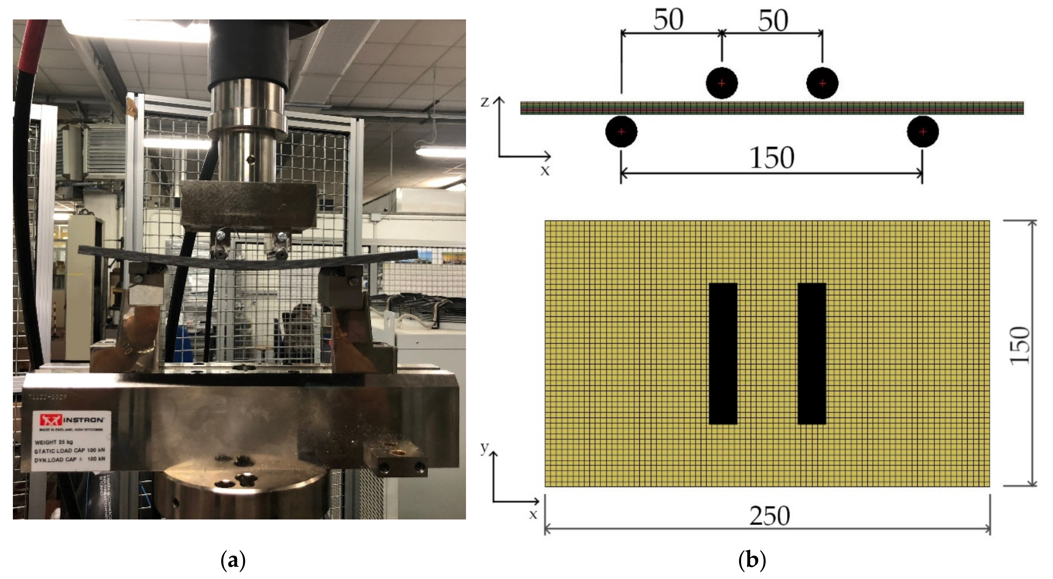
2.2. Experimental Tests
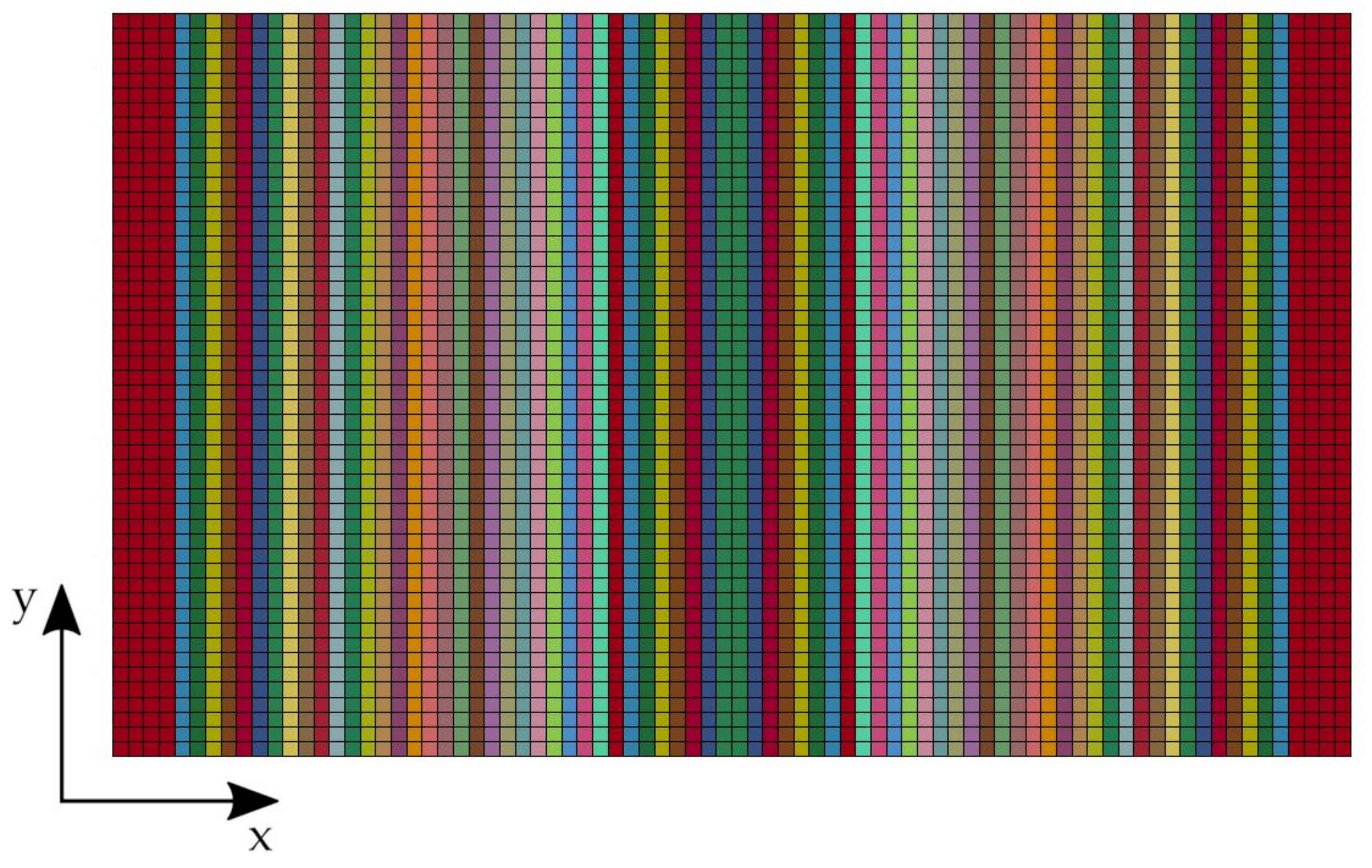
2.3. Numerical Model
- when the product returns a negative value, the derivate at the k-th location is assumed equal to zero. This can be justified by considering that a change in the sign of the difference quotient implies a change in the derivative of the function, as well;
- when the sign of the product is positive, the derivate at the k-th location is assumed equal to average value ;
- the derivates at the extremities, and , are assumed equal to zero.
3. Results
3.1. Four-Point Bending Test: Experimental Results and Numerical Model Tuning
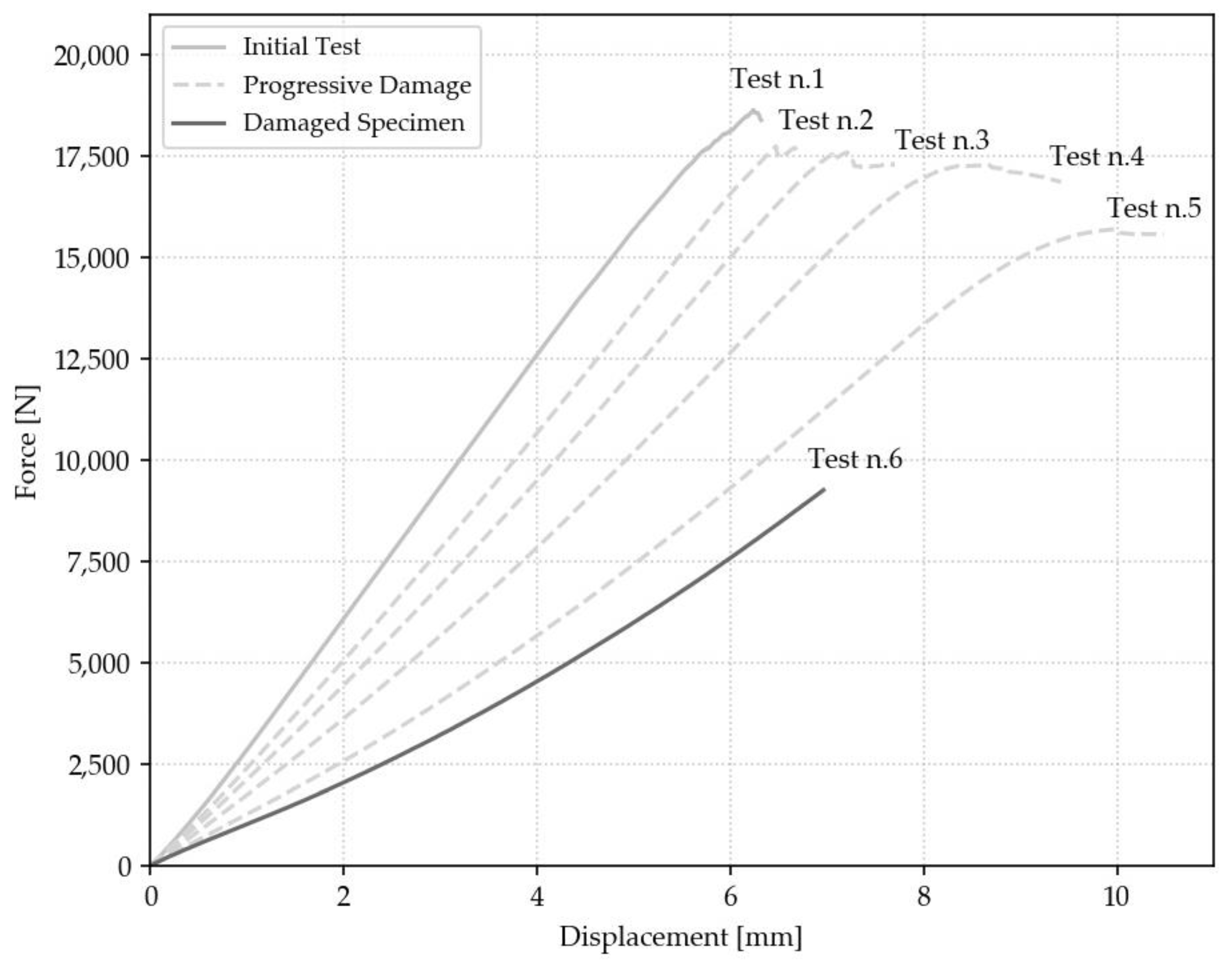
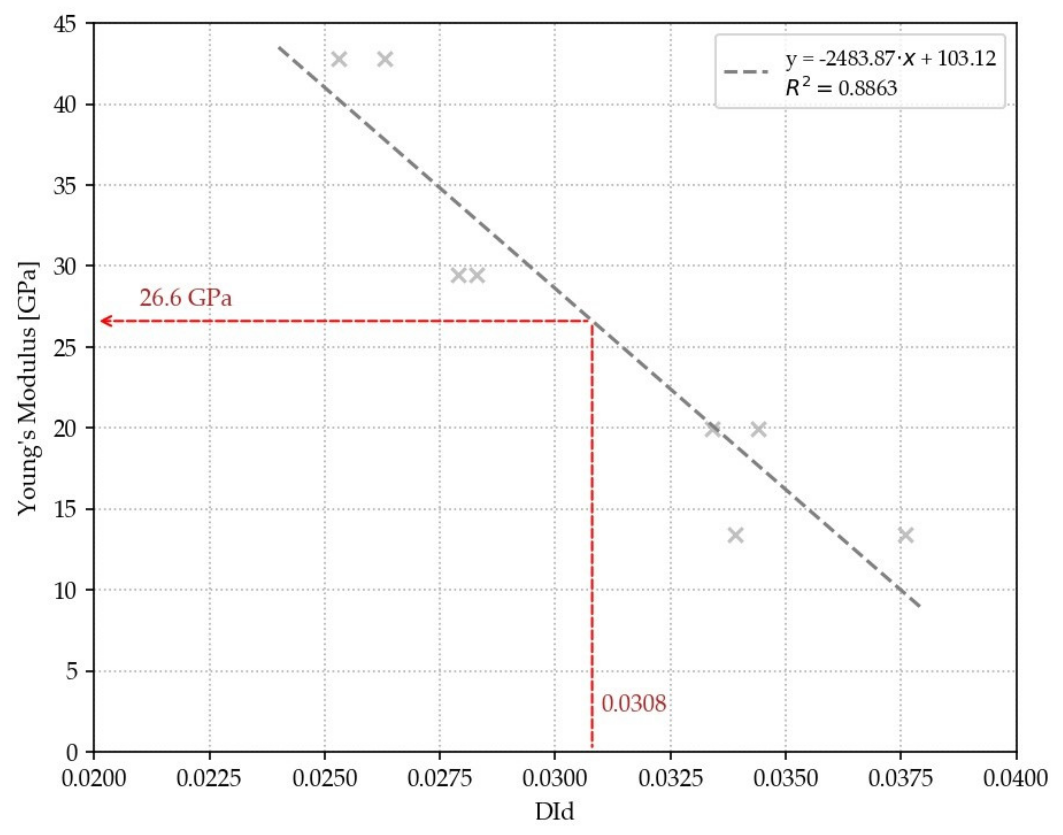
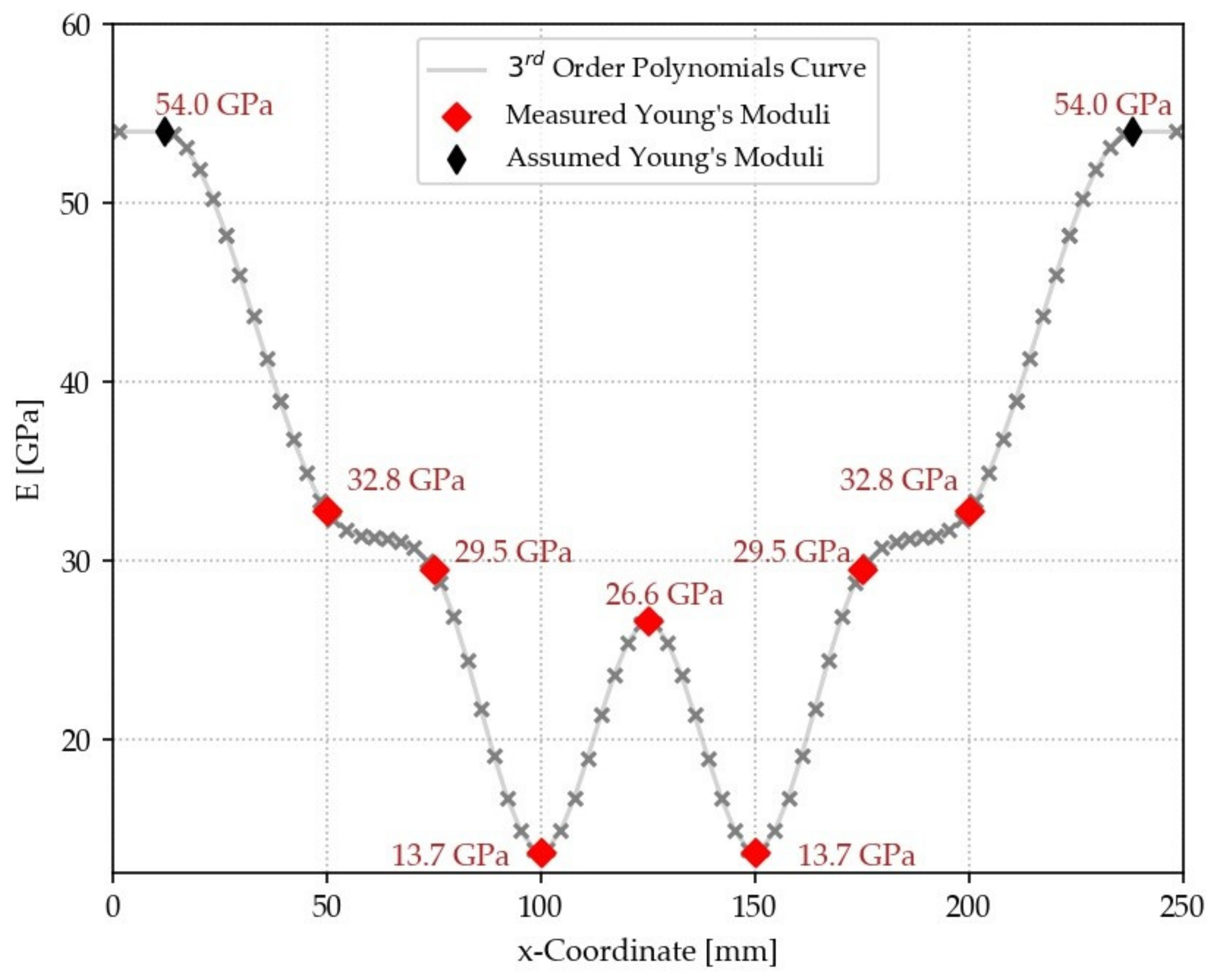
3.2. Progressive Damaging and Assessment of Residual Elastic Properties through the DId Technique
3.3. Validation: Comparison of Experimental and Numerical Results
4. Conclusions
Author Contributions
Funding
Conflicts of Interest
References
- Heslehurst, R.B. Defects and Damage in Composite Materials and Structures; CRC Press: Boca Raton, FL, USA, 2017. [Google Scholar]
- Ibrahim, M.E. Nondestructive testing and structural health monitoring of marine composite structures. In Marine Applications of Advanced Fibre-Reinforced Composites; Woodhead Publishing: Cambridge, UK, 2016; pp. 147–183. [Google Scholar]
- Hubschen, G.; Altpeter, I.; Tschuncky, R.; Herrmann, H. Materials Characterization Using Nondestructive Evaluation (NDE) Methods; Woodhead Publishing: Cambridge, UK, 2016. [Google Scholar]
- Katunin, A.; Danczak, M.; Kostka, P. Automated identification and classification of internal defect in composite structures using computed tomography and 3D wavelet analysis. Arch. Civ. Mech. Eng. 2015, 15, 436–448. [Google Scholar] [CrossRef]
- Junyan, L.; Liqiang, L.; Yang, W. Experimental study on active infrared thermography as a NDI tool for carbon–carbon composites. Compos. Part B Eng. 2013, 45, 47–138. [Google Scholar] [CrossRef]
- Tam, J.H.; Ong, Z.C.; Ismail, Z.; Ang, B.C.; Khoo, S.Y. Identification of material properties of composites materials using nondestructive vibrational evaluation approaches: A review. Mech. Adv. Mater. Struct. 2017, 24, 971–986. [Google Scholar] [CrossRef]
- ASTM. E1876-15 Standard Test Method for Dynamic Young’s Modulus, Shear Modulus, and Poisson’s Ratio by Impulse Excitation of Vibration; ASTM International: West Conshohocken, PA, USA, 2015. [Google Scholar]
- ASTM. C1259-15 Standard Test Method for Dynamic Young’s Modulus, Shear Modulus, and Poisson’s Ratio for Advanced Ceramics by Impulse Excitation of Vibration; ASTM International: West Conshohocken, PA, USA, 2015. [Google Scholar]
- Paolino, D.S.; Geng, H.; Scattina, A.; Tridello, A.; Cavatorta, M.P.; Belingardi, G. Damaged composites laminates: Assessment of residual Young’s modulus through the Impulse Excitation Technique. Compos. Part B Eng. 2017, 128, 76–82. [Google Scholar] [CrossRef]
- Garnier, C.; Pastor, M.L.; Eyma, F.; Lorrain, B. The detection of aeronautical defects in situ on composite structures using Non-Destructive Testing. Compos. Struct. 2011, 93, 36–1328. [Google Scholar] [CrossRef]
- Belingardi, G.; Cavatorta, M.P.; Paolino, D.S. A new damage index to monitor the range of the penetration process in thick laminates. Compos. Sci. Technol. 2008, 68, 2646–2652. [Google Scholar] [CrossRef][Green Version]
- Belingardi, G.; Cavatorta, M.P.; Paolino, D.S. Repeated impact response of hand layup and vacuum infusion thick glass reinforced laminates. Int. J. Impact Eng. 2008, 35, 609–619. [Google Scholar] [CrossRef]
- Belingardi, G.; Cavatorta, M.P.; Paolino, D.S. On the rate of growth and extent of the steady damage accumulation phase in repeated impact tests. Compos. Sci. Technol. 2009, 69, 1693–1698. [Google Scholar] [CrossRef]
- Belingardi, G.; Cavatorta, M.P.; Paolino, D.S. Single and repeated impact tests on fiber composite laminates: Damage index vs. residual flexural properties. In Proceedings of the 17th International Conference for Composite Materials. Edinburgh, UK, 27–31 July 2009. [Google Scholar]
- Tridello, A.; D’Andrea, A.; Paolino, D.S.; Belingardi, G. A novel methodology for the assessment of the residual elastic properties in damaged composite components. Compos. Struct. 2017, 161, 435–440. [Google Scholar] [CrossRef]
- Yam, L.H.; Wei, Z.; Cheng, L. Nondestructive detection of internal delamination by vibration-based method for composite plates. J. Compos. Mater. 2004, 38, 98–2183. [Google Scholar] [CrossRef]
- LSTC. LS-DYNA Keyword Manual Volume I. 2019. [Google Scholar]
- LSTC. LS-DYNA Keyword Manual Volume II. 2019. [Google Scholar]
- Muflahi, S.A.; Mohamed, G.; Hallett, S.R. Investigation of delamination modeling capabilities for thin composite structures in LS-DYNA. In Proceedings of the 13th International LS-DYNA Users Conference, Detroit, MI, USA, 8–10 June 2014. [Google Scholar]
- Williams, K.V.; Vaziri, R.; Floyd, A.M.; Poursatip, A. Simulation of damage progression in laminated composite plates using LS-DYNA. In Proceedings of the 5th International LS-DYNA Users Conference, Southfield, Dearborn, MI, USA, 9–11 April 1998. [Google Scholar]
- Moncayo, E.D.; Wagner, H.; Dreschler, K. Benchmarks for composite delamination using LS-DYNA 971: Low velocity impact. In Proceedings of the German LS-DYNA Forum, Frankenthal, Gemany, 11–12 October 2007. [Google Scholar]
- ASTM. D6272−17. Standard Test Method for Flexural Properties of Unreinforced and Reinforced Plastics and Electrical Insulating Materials by Four-Point Bending; ASTM International: West Conshohocken, PA, USA, 2017. [Google Scholar]
- ASTM. D5628-10. Standard Test Method for Impact Resistance of Flat, Rigid Plastic Specimens by Means of a Falling Dart (Tup or Falling Mass); ASTM International: West Conshohocken, PA, USA, 2010. [Google Scholar]
- LSTC. LS-DYNA Theory Manual. 2019. [Google Scholar]


| Property | Value |
|---|---|
| Density | 1.45 103 g/cm3 |
| Young’s modulus in longitudinal and transverse direction () | 54 GPa |
| Shear modulus () | 3.5 GPa |
| Poisson’s ratio () | 0.08 |
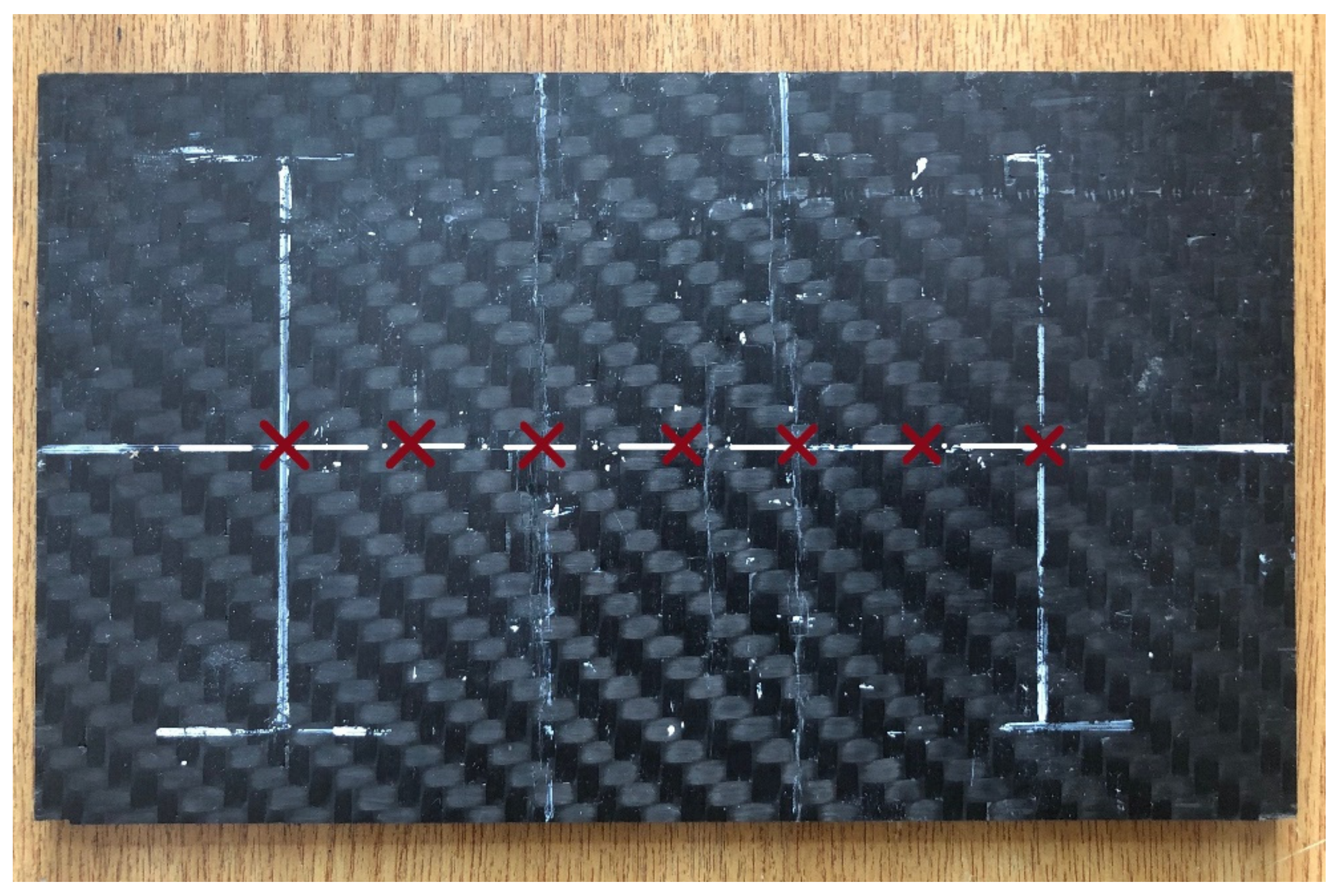
| X-Coordinate [mm] | ||
|---|---|---|
| 50 | 0.0283 | 32.8 |
| 75 | 0.0297 | 29.5 |
| 100 | 0.036 | 13.7 |
| 125 | 0.0308 | 26.6 |
| 150 | 0.036 | 13.7 |
| 175 | 0.0297 | 29.5 |
| 200 | 0.0283 | 32.8 |
© 2019 by the authors. Licensee MDPI, Basel, Switzerland. This article is an open access article distributed under the terms and conditions of the Creative Commons Attribution (CC BY) license (http://creativecommons.org/licenses/by/4.0/).
Share and Cite
Boursier Niutta, C.; Tridello, A.; Ciardiello, R.; Belingardi, G.; Paolino, D.S. Assessment of Residual Elastic Properties of a Damaged Composite Plate with Combined Damage Index and Finite Element Methods. Appl. Sci. 2019, 9, 2579. https://doi.org/10.3390/app9122579
Boursier Niutta C, Tridello A, Ciardiello R, Belingardi G, Paolino DS. Assessment of Residual Elastic Properties of a Damaged Composite Plate with Combined Damage Index and Finite Element Methods. Applied Sciences. 2019; 9(12):2579. https://doi.org/10.3390/app9122579
Chicago/Turabian StyleBoursier Niutta, Carlo, Andrea Tridello, Raffaele Ciardiello, Giovanni Belingardi, and Davide Salvatore Paolino. 2019. "Assessment of Residual Elastic Properties of a Damaged Composite Plate with Combined Damage Index and Finite Element Methods" Applied Sciences 9, no. 12: 2579. https://doi.org/10.3390/app9122579
APA StyleBoursier Niutta, C., Tridello, A., Ciardiello, R., Belingardi, G., & Paolino, D. S. (2019). Assessment of Residual Elastic Properties of a Damaged Composite Plate with Combined Damage Index and Finite Element Methods. Applied Sciences, 9(12), 2579. https://doi.org/10.3390/app9122579