Article

Auto-Generation System Based on Fractal Geometry for Batik Pattern Design

Key Laboratory of Advanced Manufacturing Technology (Guizhou University), Ministry of Education, Guiyang 550003, China
*
Author to whom correspondence should be addressed.
Appl. Sci. 2019, 9(11), 2383; https://doi.org/10.3390/app9112383
Submission received: 7 May 2019 / Revised: 29 May 2019 / Accepted: 6 June 2019 / Published: 11 June 2019

Abstract

:

Featured Application

This study proposes an auto-generation system for batik patterns design, which is conducive to the spread and promotion of intangible culture such as batik. Ordinary users can use this system to generate their favorite batik patterns for personalization. The system can assist in the creation of batik patterns to promote artistic creation.

Abstract

In order to obtain the automatic simulation generation of traditional handmade batik patterns in a computer, this paper proposes the automatic generation method of batik flower patterns based on fractal geometry. Firstly, we analyze the fractal characteristics of batik flowers and design an automatic flower generation algorithm based on a two-dimensional iterated function system (IFS) and a curve function. The algorithm forms a complete flower pattern. Secondly, a nonlinear function is defined and the flower pattern is introduced into the nonlinear function to iterate and change. On this basis, we present an automatic generation method of different distribution patterns for flower patterns which obtains the most effective range of each parameter value for each function. Finally, in order to verify the feasibility of the automatic generation method of batik flower patterns, we develop an automatic generation experiment system for batik patterns via an interactive way of working. The results show that the user or designer can quickly and automatically simulate a series of flower patterns by changing the relevant parameter values, realizing the digitization and innovative design of the pattern and enriching the batik pattern base.

1. Introduction

Batik is one of three printing techniques which were used in ancient China. It is a handicraft of traditional textile printing and dyeing performed by ethnic minorities in China and is part of the outstanding intangible cultural heritage of China. Batik patterns overwhelmingly have high artistic value and have recorded and expressed the development, changes, and spread of Chinese minority culture. Various elements are first combined to form a series of basic patterns which are then repeated and combined in order to produce a complete batik pattern, as shown in Figure 1. The layout map usually consists of a four-square layout and is obtained by the repeated transformation of a single pattern. Typically, the main pattern is selected, transformed, and then a dotted decorative pattern is added to create a final layout pattern. These basic patterns are obtained by depicting objects in the natural environment, and mainly include natural patterns and geometric patterns, with the natural patterns including animal patterns and plant patterns [1].
Plant patterns mainly include leaves, chrysanthemums, lotuses, peaches, sunflowers, cockscombs, and so on. Guizhou ethnic minorities live in a natural environment of beautiful mountains and rivers and the beautiful scenery inspires their creation. The patterns are painted with bold changes and exaggerated treatment without being limited by the real objects. The flowers and plants in the mountain stream become the objects of creation because they can draw out varieties of the subject matter by the sort of plants and flowers’ appearance with disparate style. Guizhou batik uses a large number of plants and flowers which can not only be seen everywhere in daily life but also contain good wishes and hopes [2]. Flowers are a common and popular plant pattern, because they represent the prosperous and propitious wishes of the family.
The traditional batik production method is purely manual. It is of extremely low production efficiency, which is not conducive to the spread, development, and promotion of intangible cultural heritage. It is a mode of work which is not conducive to the individualization of batik patterns in batik products nor the intelligent upgrade of China’s printing and dyeing industry. As a result, computer graphics have begun to be used in pattern design to convert traditional batik patterns into digital patterns. Intelligent design technology used to generate digital patterns is not only conducive to the digital protection of traditional batik and enriching the diversity of batik patterns but also can adapt to the intelligent upgrading of China’s printing and dyeing industry. The automatic generation system proposed in this paper can not only adapt to the intelligent upgrade of the printing and dyeing industry but also promote the development of the printing and dyeing industry, and is conducive to the dissemination and promotion of non-material culture such as batik. Ordinary users can use the system to generate favorite batik patterns for personalization. Designers can use the system to assist in the artistic creation of batik patterns to facilitate artistic creation.
Applying digital technology to the design of traditional batik patterns can significantly enrich the batik patterns. Zhang Xiaohong [3] has proposed combining fractal matrix iteration with the automatic evolution of cloud model cells and has generated a large number of fractal patterns by setting times of iteration and evolution. However, the details of the artistic pattern generated are uncertain. Cui Jia [4], based on the shape grammars method, has used a free B-spline curve in the Zhuang embroidery design to derive an initial design concept and a new difference algorithm. Its feature matrix, however, is specified by the expert or system designer and cannot be adjusted automatically. Li Shiguang [5] has proposed a specific method for simulating batik printing patterns according to the characteristics of cracks in batik printing patterns, which can only produce cracks related to batik patterns. In order to solve the shortcomings, as mentioned above, of the generated patterns, this paper proposes an automatic generation method of batik flower patterns based on a fractal geometry iterated function system (IFS). It can not only effectively simulate traditional hand-dyed batik flower patterns but also quickly and automatically simulate a series of flower patterns by changing the relevant parameter values to realize the digital design of the batik flower pattern.
The paper is organized as follows. In Section 2 we briefly introduce the current state of fractal geometry and fractal pattern generation. The fractal features of batik flower patterns and the fractal method of IFS are introduced in Section 3. The flow of the algorithm and the automatic generation process is presented in Section 4. After the experiment and analysis, the valid value of each parameter in the algorithm function is obtained in Section 5. The automatic generation system for batik patterns is introduced in Section 6. In Section 7 we analyze and compare the features of original batik patterns and generated patterns. Finally, conclusions and future work are given in Section 8.

2. Related Work

2.1. Fractal Geometry

Fractal geometry, also known as “nature’s geometry”, is a kind of geometry that studies irregular geometry. Irregular geometry refers to those seemingly chaotic rules with specific internal laws, such as meandering coastlines and rolling mountains. The research object of traditional geometry is the integer dimension, e.g., zero-dimensional points, one-dimensional lines, two-dimensional surfaces, and three-dimensional solids. The research object of fractal geometry is a non-negative real number dimension such as 0.63.
On that basis, fractals have the following characteristics [6].
  • Self-similarity, which may include precise self-similarity—the same at all scales; quasi-self-similarity—similar patterns on different scales, where small copies of the entire fractal may contain distorted and degenerate forms; statistical self-similarity—random repetition of a pattern so that a number or statistical measurement remains across scales [7]; qualitative self-similarity—such as time series [8]; or multifractal scaling [9,10,11,12]—represented by multiple fractal dimensions or scaling rules.
  • Fine or detailed structure on any small scale. The result of this structure is that fractals may have emergent properties [13].
  • Local and global irregularities are not easily described in traditional Euclidean geometric languages. For images of fractal patterns, this has been expressed by phrases such as “smoothly stacked surfaces” and “whirlpools on vortices” [14].
Fractals can be created by the following fractal generating technologies.
  • IFS—uses fixed geometric replacement rules; may be stochastic or deterministic [15,16].
  • Strange attractors—use iterations of a map or solutions of a system of initial-value differential or difference equations that exhibit chaos.
  • L-systems—use string rewriting; may resemble branching patterns or turtle graphics patterns [17,18].
  • Escape-time fractals—use a formula or recurrence relation at each point in a space (such as a complex plane); usually quasi-self-similar; also known as “orbit” fractals.
  • Random fractals—use stochastic rules.
  • Finite subdivision rules—use a recursive topological algorithm for refining tiling [19] and are similar to the process of cell division [20].
Hence, in this paper, fractal geometry can be used to generate flower patterns with self-similarity, self-affine, and scale-free characteristics.

2.2. Fractal Pattern Generation

At present in the reprinting and dyeing industry, pattern generation based on fractal geometry is a research hotspot.
Hariadi [21] has used the Fourier transform to directly generate as a batik master pattern a pattern with fractal features. Aswin [22] has proposed a fractal pattern generated by an L-system as a decorative pattern. In the literature [23,24,25], starting from the fractal characteristics of the batik pattern, the above fractal technique has been used to generate various fractal patterns similar to traditional batik patterns. The fractal pattern is similar to the traditional batik pattern in spirit but not in shape. Muhamad [26] and his team, the “Pixel People Project”, developed the software jBatik for the simulation of Indonesian-style digital wax patterns based on fractal algorithms; the software is not universal for printing and dyeing patterns in other areas such as China and Africa, however.
Zhang Dongya [27] has used Visual Basic language to study single-rule and multi-rule algorithms in a deterministic L-system and has obtained a rich and varied L-system graph by transforming the parameters in the algorithm. However, only a few pattern generation methods can be implemented, so it is necessary to study the generation characteristics and rules of other types of maps. Yuan Qingni [28] has proposed using an iterated function system to generate a bionic butterfly pattern as a batik pattern. However, this method can only generate butterfly patterns and is not universal. Zhang Xinwei [29] has improved the shape grammar and applied it to the formal expression of pattern configuration and at the same time has proposed the manual and automatic extraction of configuration based on this method. However, this method cannot extract fractal patterns, and the efficiency of the algorithm has room for improvement.
Yuan Huifen [30] has proposed a fractal pattern generation method based on the matrix Kronecker product and has applied it to the design of Wangjiang cross stitch. It is necessary, however, to establish a pattern Boolean matrix model and carry out multilevel fractal processing. Wang Shuhuan [31] has used the programming software Visual Basic6.0 to study the generation method of the Mandelbrot set and Julia set on a complex plane to realize its visualization. A series of varying fractal maps were obtained by changing the form of the iterative function and the fractal pattern was applied to the textile using printing techniques. However, the fractal image needed to be selected and processed with the help of Photoshop which is an image processing software. Lu Lisa [32] has used the C++ language to write a fractal pattern based on generator and escape time algorithms and has conducted a secondary design of the generated pattern in pattern design software. Finally, the designed pattern program was woven.
In this paper, fractal geometrics using a combination of an iterated function system and curve function can not only automatically generate batik flower patterns but also can automatically generate a series of different flower patterns merely by modifying the parameter values.

3. Fractal Characteristics of Batik Patterns and Fractal Algorithms

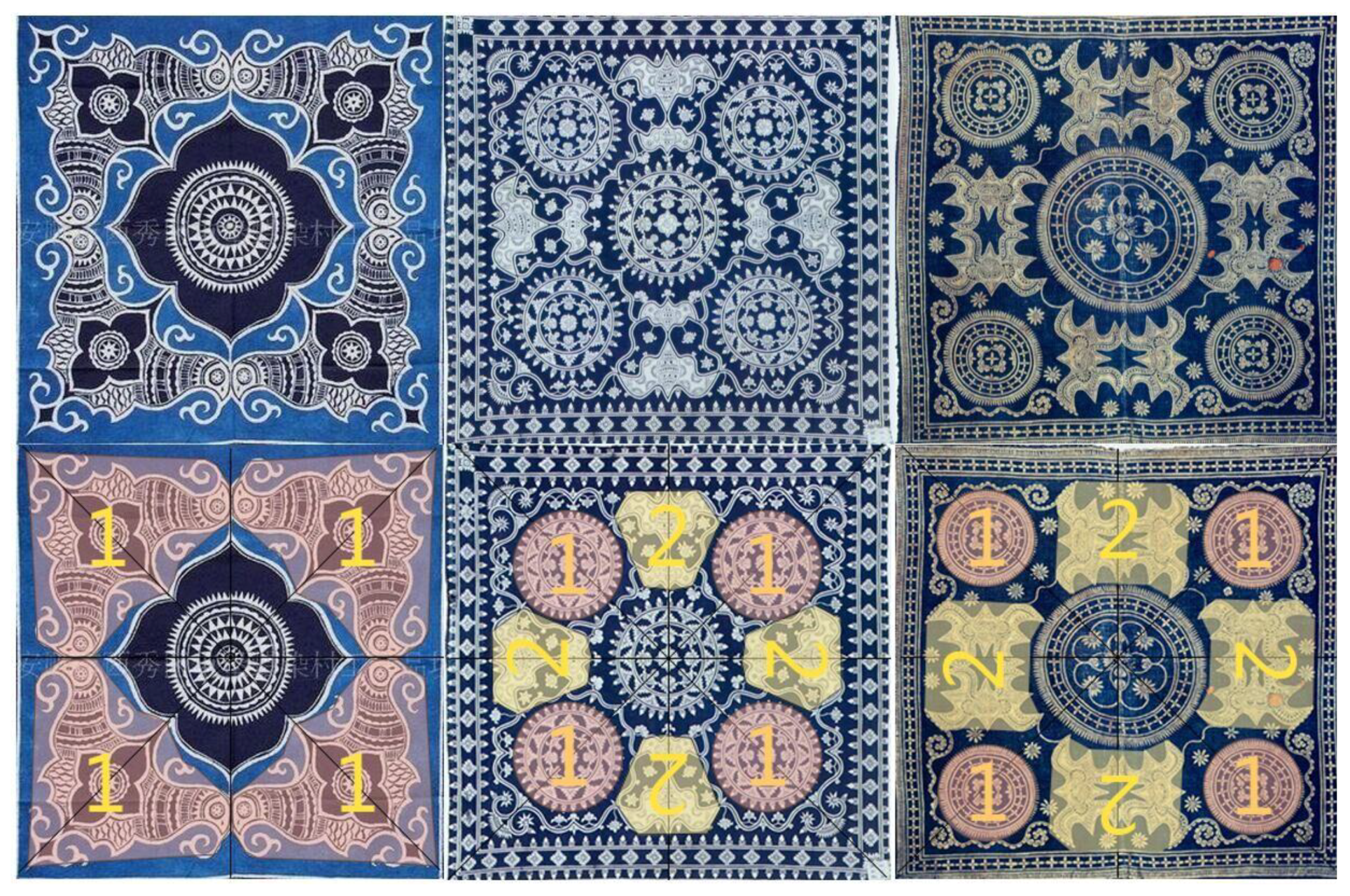
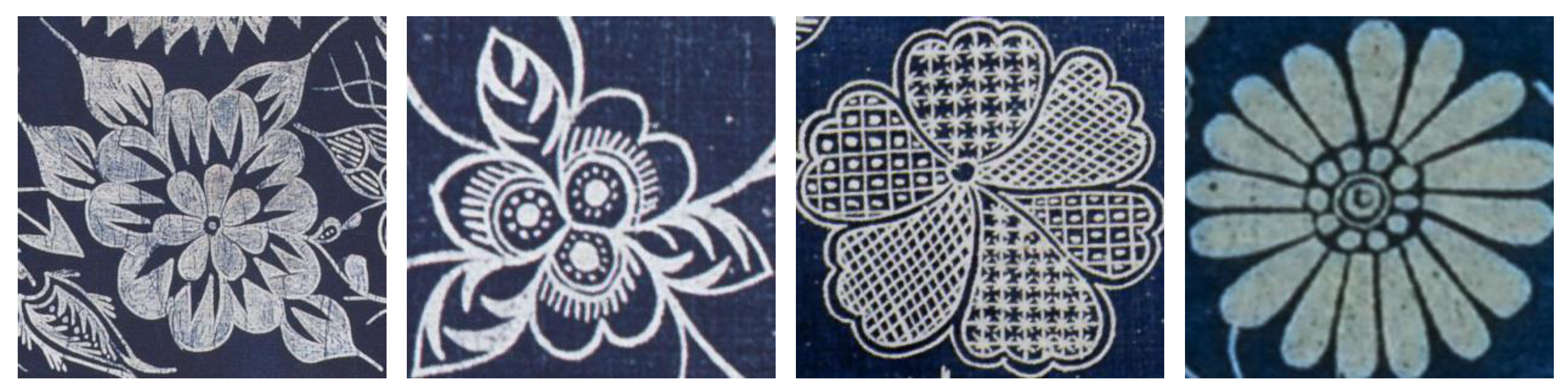
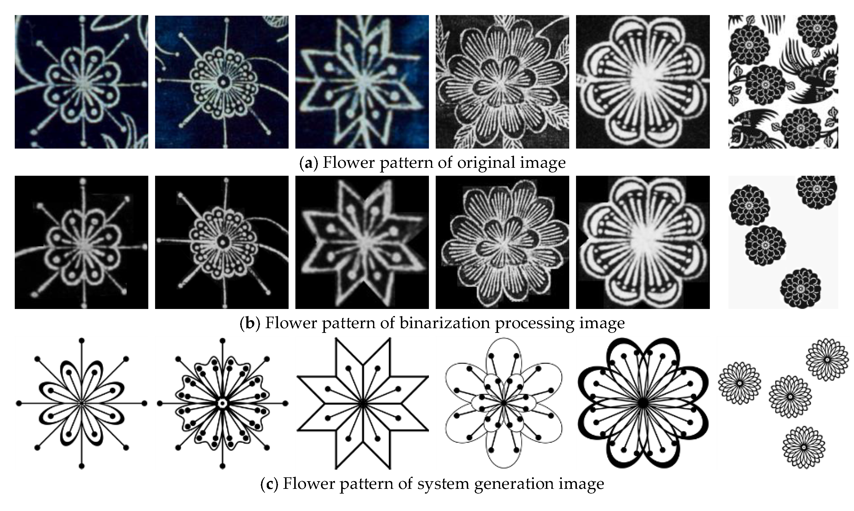
3.1. Fractal Characteristic of Batik Flower Patterns

The batik pattern is of symbolic significance. The flower pattern of traditional batik indicates the prosperous and propitious wealth of the family. In Figure 2, we can see that the batik flower pattern has a self-similar characteristic. In the first pattern, the inner and outer petals are quasi-self-similar. In the second pattern, the outer layer of the dotted pattern in the petals is self-similar to the central pattern. In the third and fourth patterns, with regard to the boundary contour of the petals, these are obtained by affine changes of an individual petal. That is to say, these patterns of the flower have same or similarly shaped features in different hierarchies. There is a relationship between the different hierarchies that governs enlargement, reduction, or affine change. It can be seen that this is a self-similar pattern because fractal patterns can be almost the same at different levels and fractal geometry can be applied to the design of batik flower patterns. It can be seen from Figure 1 that the overall layout of the batik pattern is mainly symmetrical, double-square, four-square, or circular. These layouts have the self-similarity, self-affine, and scale-free characteristics of fractals.

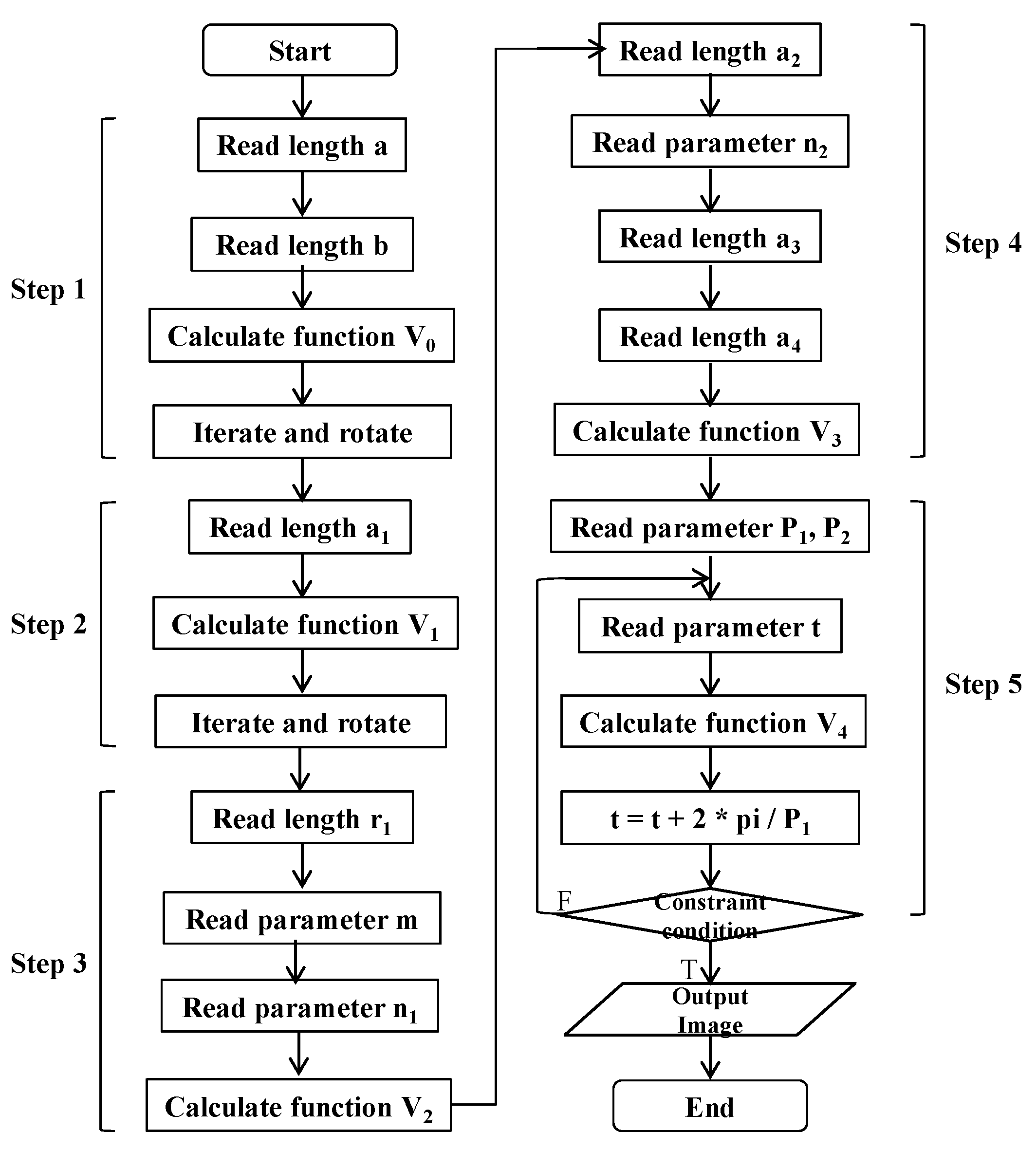
3.2. Iterated Function System

IFS is one of the most commonly used fractal methods. The graphics generated by this method are self-similar. Fractal geometry is dissimilar from traditional geometry. The fractal graph produced by the IFS is usually not an integer dimension and can be of an arbitrary dimension. The fractal graph is usually calculated and drawn in a two-dimensional plane space.
A two-dimensional IFS is a finite collection of n functions Fi from R2 to R2. The solution of the system is the set S in R2 (and hence an image) that is the fixed point of Hutchinson’s recursive set equation [33]:
S = i = 0 n 1 F i ( S ) ,
In Equation (1), as implemented and popularized by Barnsley [34], the functions Fi (see Equation (2)) are linear (technically they are affine as each is a two by three matrix capable of expressing scale, rotation, translation, and shear):
F i ( x , y ) = ( a i x + b i y + e i , c i x + d i y + f i ) ,
In order to facilitate the proofs and guarantee convergence of the algorithms, the functions are normally constrained to be contractive, that is, to bring points closer together.

4. Auto-Generation Algorithm Based on Fractal Geometry

In this work, an auto-generation algorithm based on fractal geometry was used to design batik flower patterns. Two-dimensional IFS implemented the algorithm in the fractal method. The algorithm mainly includes two parts: generation of essential flower patterns and generation of different flower layout patterns. In the first step, the essential elements of flower leaves are generated through a superellipse curve function and iterated repeatedly to create the flower leaves pattern. In the second step, the essential elements of petals are generated by the function of the rose curve and are repeatedly iterated to generate the pattern of the petals. In the third step, the pistil pattern is generated by the Hypocycloid function. In the fourth step, the function of the rose curve and circular curve is used to generate the pattern of the flower core and an entire flower pattern is generated by combining the above patterns. In the fifth step, the transformation function is used to iterate the entire flower pattern to generate various pattern layouts. According to the number of iterations, a flower pattern layout such as a symmetrical layout, double-square layout, or four-square layout can be generated. The algorithm flow is shown in Figure 3.

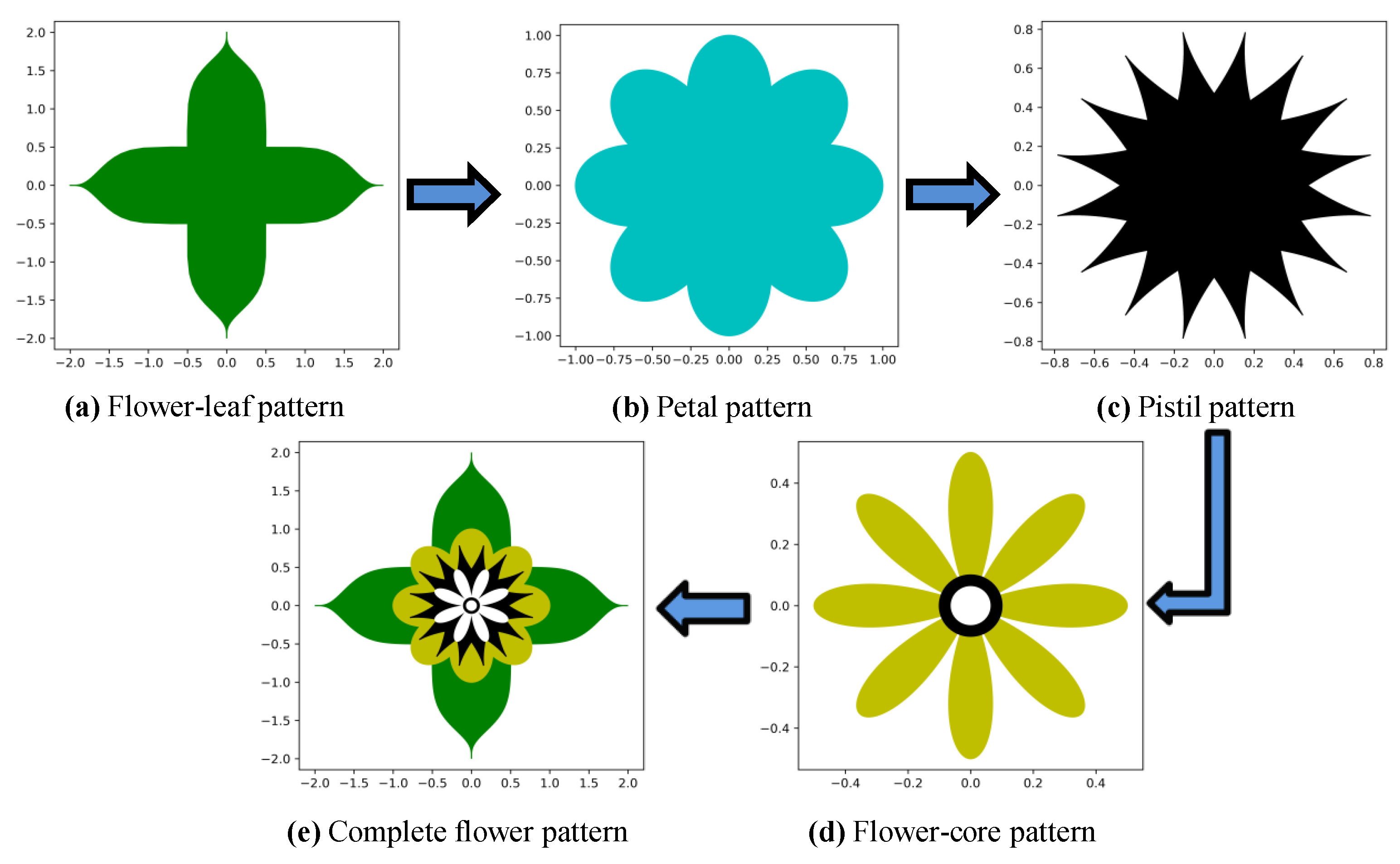
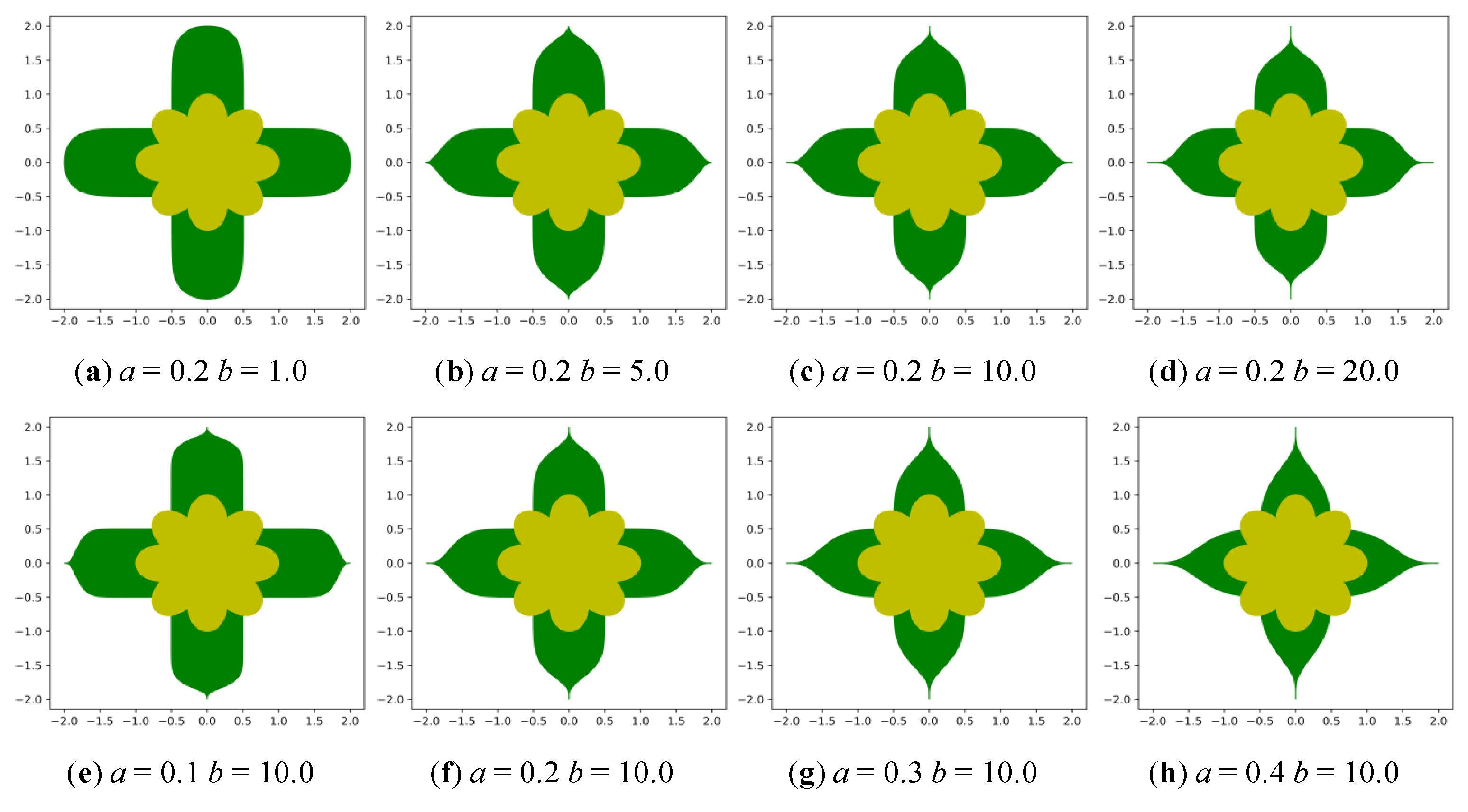
4.1. Generating the Flower-Leaves Pattern

The basic shape of the flower-leaves was based on a generalization of the Gabriel Lame curve or the superellipse curve, which is a closed curve similar to an ellipse which retains the geometric features of the semi-major axis and the semi-minor axis but has different overall shapes. In the Cartesian coordinate system, the curve equation may be given as
s g n ( x ) = {     1 ,    x > 0     0 ,    x = 0 1 ,    x < 0 ,
| x a | n + | y b | n = 1   o r   { x ( t ) = a × | cos ( t ) | 2 n × s g n ( cos ( t ) ) y ( t ) = b × | sin ( t ) | 2 n × s g n ( sin ( t ) ) ,
where n, a, and b are positive numbers. When n is a positive number p/q, each quadrant of the hyperelliptic curve is a pq-order planar algebraic curve [35]. In particular, when a = b = 1 and n is an even number, it is an n-order Fermat curve. In this case it is non-singular but in general it is singular. If the numerator is not even, the curves are stitched together from portions of the same algebraic curve in different directions.
Thus, after the proper transformation of form, the superellipse curve equation applicable to the Cartesian coordinate system is obtained, and may be written as
{ x ( t ) = r 1 × | cos ( t ) | a × s g n ( cos ( t ) ) y ( t ) = r 2 × | sin ( t ) | b × s g n ( sin ( t ) )   a , b > 0 , t [ 0 , π ] ,
where r1 represents the length of the semi-major axis and r2 represents the length of the semi-minor axis. Note that t is not a fixed angle of the figure but is just a parameter.
Hence, we can apply the nonlinear function V0 to generate the essential elements of the flower leaves.
V 0 : { x ( t ) = l × 2 × | cos ( t ) | a × s g n ( cos ( t ) ) , l [ 0 , 1 ] , t [ 0 , π ] y ( t ) = l × 0.5 × | sin ( t ) | b × s g n ( sin ( t ) ) , a > 0 , b > 0 ,
In Equation (6), the parameters a and b jointly control the shape of the flower-leaves pattern and the parameter l controls the size of the flower-leaves pattern.
Subsequently, repeated iterations are carried out based on function V0 and each iteration function is represented by V0j, but each iteration is only a repeated mapping of the graph. Then, a mixed vector coefficient Vij is introduced to change the pattern of repeated mapping. So
F 0 i ( x , y ) = j v i j V 0 j ( x , y ) ,
where the iteration parameter i is an integer that changes sequentially from 0 to n-1. Using this extension, we obtain the flower-leaves pattern function F0(x, y) based on Equation (7), as shown in Figure 4a.

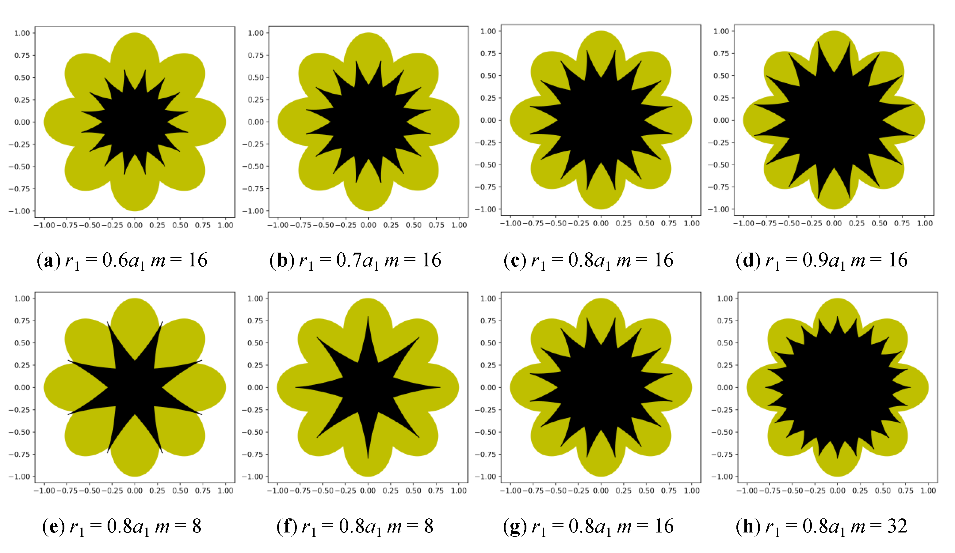
4.2. Generating the Petals Pattern

The basic shape of the petals was generated based on a rhodonea curve or a rose curve, which was plotted in the polar coordinate system as [36,37]
ρ = cos ( n θ )   or   ρ = sin ( n θ ) ,
where n is a positive integer. Where n is an even number, when the value of θ changes from 0 to 2π, the entire graph of the rose will be accurately drawn once. When n is an odd number, this will occur in the interval between 0 and π.
Thus, after the appropriate transformation of form, the rose curve equation applicable to the Cartesian coordinate system is obtained, and can be written as
{ x = a cos ( n t ) cos ( t ) y = a cos ( n t ) sin ( t ) ,
where a represents the length of the petals, the number of petals is n when n is odd, and the number of petals is 2n when n is even. The value of t ranges from 0 to 2π.
We can therefore apply the nonlinear function V1 to generate the basic elements of the petals, i.e.,
V 1 : { x = a 1 cos ( 2 t ) cos ( t ) y = a 1 cos ( 2 t ) sin ( t ) , t [ 0 , 2 π ] ,
where a1 represents the length of the petal, at which point n takes a value of 2, and the value of t ranges from 0 to 2π, meaning four petals can be generated for each iteration.
Subsequently, repeated iteration was carried out based on function V1. V1j represents each iteration function, but each iteration is only the repeated mapping of graphs. Then, a mixed vector coefficient Vij is introduced to change the pattern of repeated mapping. So
F 1 i ( x , y ) = j v i j V 1 j ( x , y ) ,
where the iteration parameter i is an integer that changes sequentially from 0 to n-1. Using this extension, we obtain the petal pattern function F1(x, y) based on Equation (11), as shown in Figure 4b.

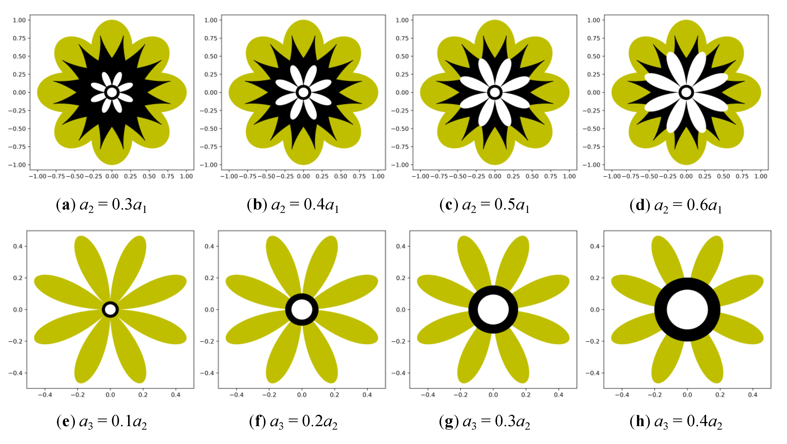
4.3. Generating the Pistils Pattern

A star shape which was generated based on the circular hypocycloid was used as the basic shape of the pistils. In geometry, the hypocycloid is a special planar curve produced by a trajectory fixed on a small circle that rolls within a larger circle. It is equivalent to a cycloid, but it is not a circle that scrolls along a line, rather, it scrolls within a circle. If the smaller circle has a radius r and the larger circle has a radius R = kr, the parametric equation of the curve can be given in any of the following ways:
{ x = ( R r ) cos ( θ ) + r   cos ( R r r θ ) y = ( R r ) sin ( θ ) r   sin ( R r r θ )   or   { x = r ( k r ) cos ( θ ) + r   cos ( ( k 1 ) θ ) y = r ( k r ) sin ( θ ) r   sin ( ( k 1 ) θ ) ,
In Equation (11), if k is a rational number, such as in the simplest terms k = p / q, then the curve has p cusps. If k is an irrational number, the curve never closes and fills the space between the larger circle and the circle of radius R − 2r.
Thus, after the proper transformation of form, the circular hypocycloid equation applicable to the Cartesian coordinate system is obtained, and can be written as
{ x = r q ( ( q 1 ) cos ( t ) + cos ( q t t ) ) y = r q ( ( q 1 ) sin ( t ) sin ( q t t ) ) q = m n , m [ 2 , 24 ] , n [ 1 , 6 ] ,
where r is the length of the pistil, m is the number of pistils, and n is used to control the shape of the cusps. We can therefore apply the nonlinear function V2 to generate the basic elements of the stamens, i.e.,
V 2 : { x = r 1 q ( ( q 1 ) cos ( t ) + cos ( q t t ) ) y = r 1 q ( ( q 1 ) sin ( t ) sin ( q t t ) ) q = m 5 , m [ 2 , 24 ] , t [ 0 , 20 π ] ,
where r1 represents the length of the pistil and m represents the number of pistils and further determines the value of n as 5.
Subsequently, repeated iteration was carried out based on function V2. V2j represents each iteration function but each iteration is only the repeated mapping of graphs. Then, a mixed vector coefficient Vij was introduced to change the pattern of repeated mapping. So
F 2 i ( x , y ) = j v i j V 2 j ( x , y ) ,
where the iteration parameter i is an integer that changes sequentially from 0 to n-1. Using this extension, the pistil pattern function F2(x, y), based on Equation (15), was able to be obtained, and is shown in Figure 4c.

4.4. Generating the Flower-Core Pattern

The basic shape of the flower-core was generated based on the rhodonea curve or the rose curve and was expressed by the curve equation in the Cartesian coordinate system as follows:
{ x = cos ( n t ) cos ( t ) y = cos ( n t ) sin ( t ) ,
Thus, after the appropriate transformation of form, the rose curve equation applicable to the Cartesian coordinate system is obtained, and can be written as
{ x = a cos ( n t ) cos ( t ) y = a cos ( n t ) sin ( t ) ,
where a represents the length of the petal and n controls the number of petals. When n is odd, the number of petals is n, and when n is even, the number of petals is 2n.
Then, the circular curve draws at the center of the flower, and Equation (18) in the Cartesian coordinate system is given as follows:
x 2 + y 2 = 1   or   { x = cos ( t ) y = sin ( t ) ,
Thus, after the proper transformation of form, the circular curve equation applicable to the Cartesian coordinate system is obtained, and may be written as
{ x = a cos ( t ) y = a sin ( t ) ,
where a is the radius of the circle and t is in the range 0 to 2π.
We can therefore apply the nonlinear function V3 to generate the basic elements of the flower-core:
V 3 : { x 31 = a 2 cos ( 4 t ) cos ( t ) y 31 = a 2 cos ( 4 t ) sin ( t ) x 32 = a 3 cos ( t ) y 32 = a 3 sin ( t ) , t [ 0 , 2 π ] ,
Subsequently, repeated iteration was carried out based on function V3. V3j represents each iteration function, but each iteration is only the repeated mapping of graphs. Then, a mixed vector coefficient Vij is introduced to change the pattern of repeated mapping. So
F 3 i ( x , y ) = j v i j V 3 j ( x , y ) ,
where the iteration parameter i is an integer that changes sequentially from 0 to n-1. Using this extension, the flower-core pattern function F3(x, y) based on Equation (21) was able to be obtained, as shown in Figure 4d.

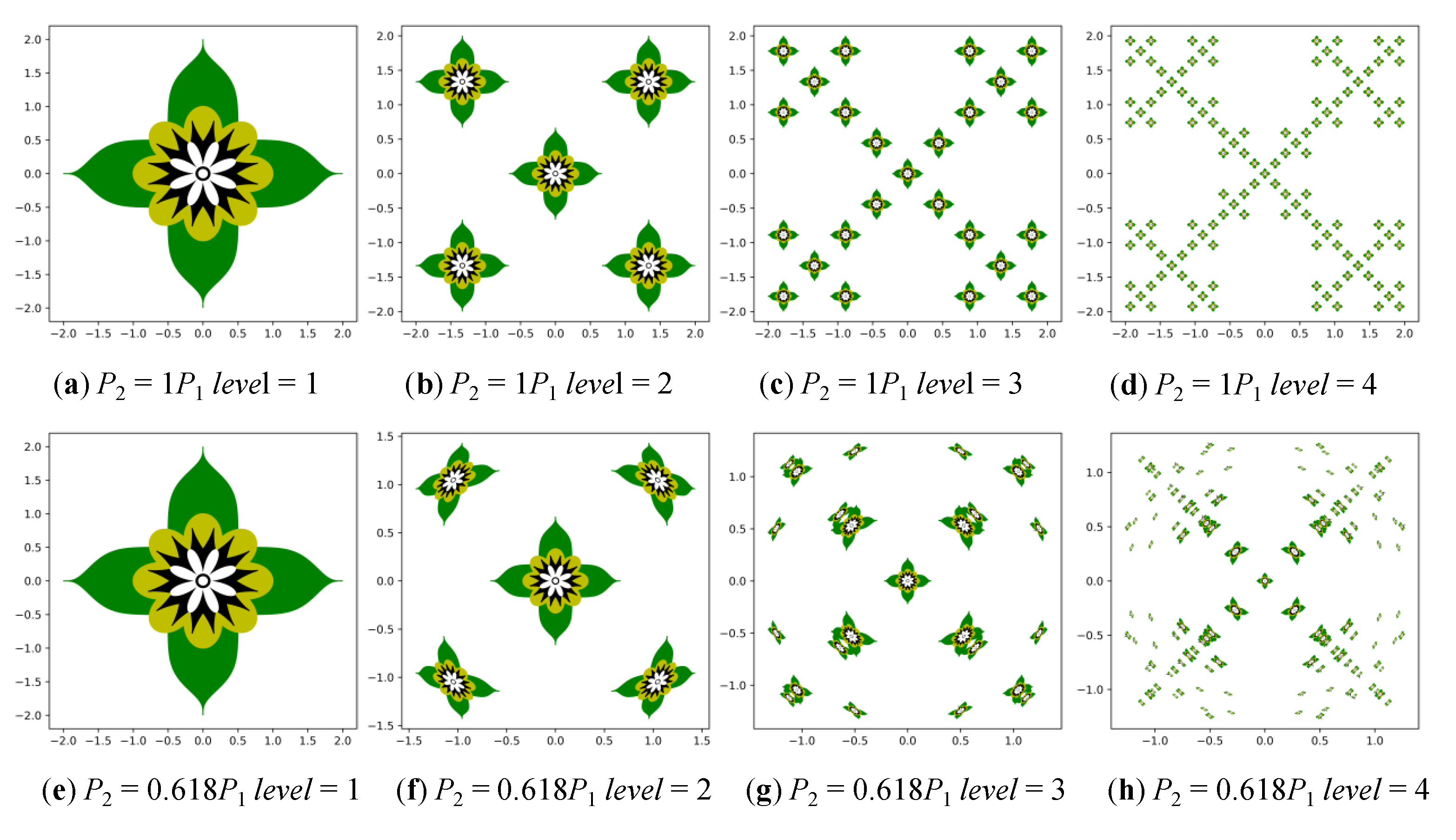
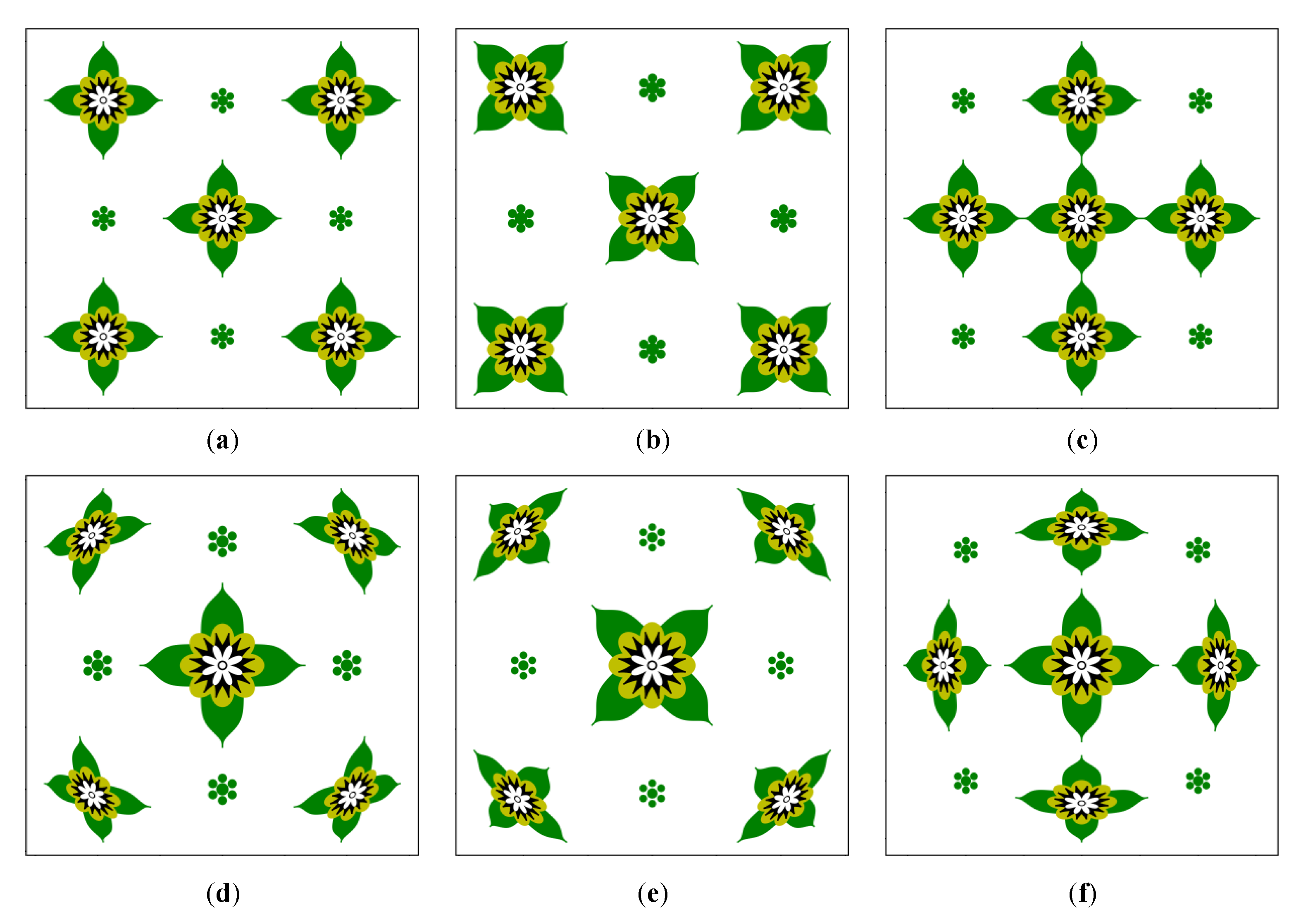
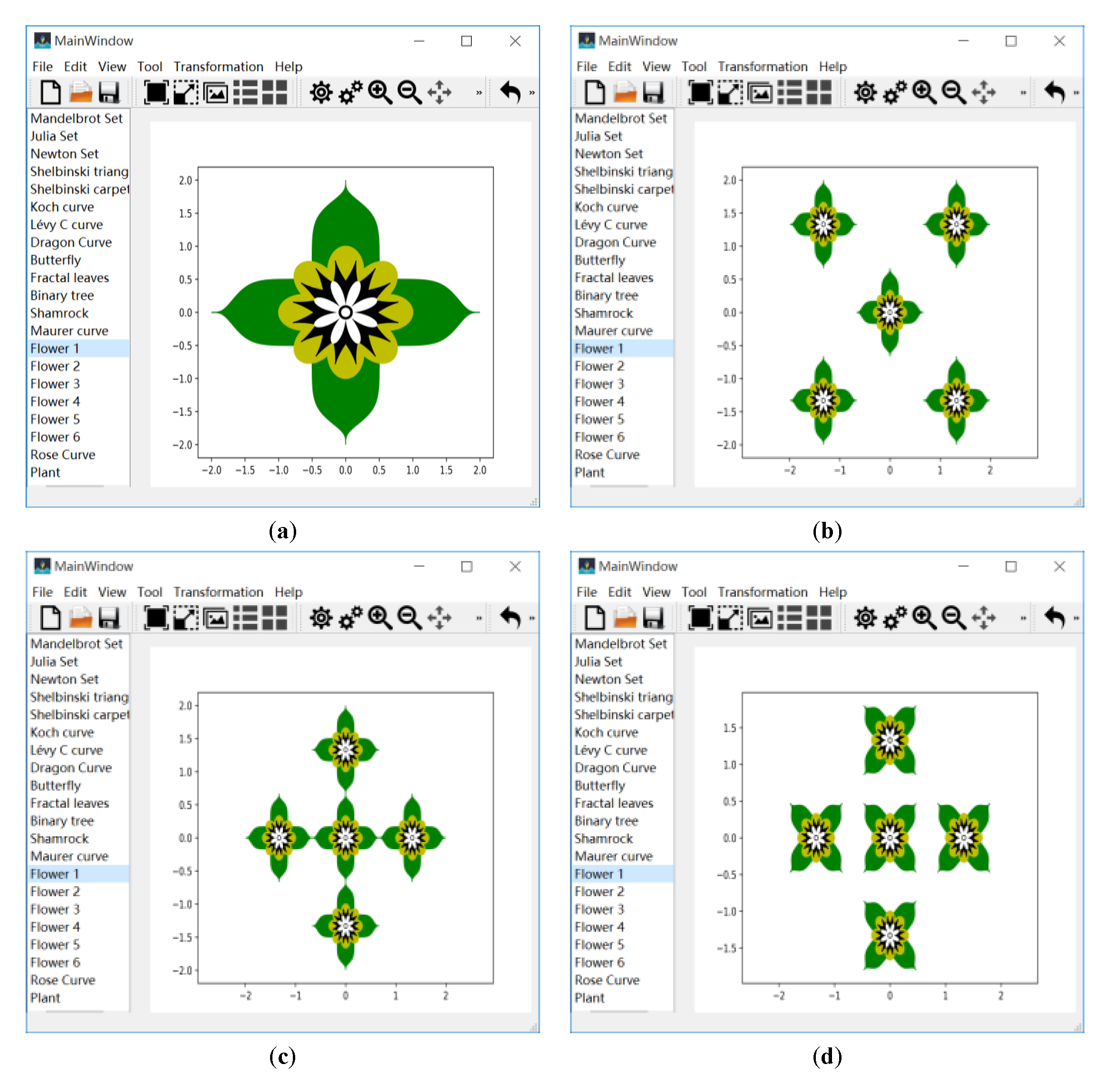
4.5. Generating the Flower Pattern Layout

Through the above process we were able to obtain the complete flower pattern. At this time, we defined a non-linear function V4, which we named JuliaN, and which contained the parameters P1 = JuliaN.Power and P2 = JuliaN.dis, where power affects the number of flower patterns and dis affects the distance from each point of the flower pattern to the origin.
V 4 : { x = r p 1 p 2 cos ( t 1 ) y = r p 1 p 2 sin ( t 2 ) ,
where t 1 = cos 1 x r + 2 π p 1 , t 2 = sin 1 y r + 2 π p 2 , r = x 2 + y 2 .
We therefore brought the complete flower pattern into function V4 and at the same time carried out iteration and change. At this time, function F4(x, y) is defined as follows:
F 4 i ( x , y ) = j v i j V 4 j ( x , y ) ,
In Equation (23), the parameter Vij is a mixed vector that causes the pattern of the repeated map to change, and the iterative parameter i is an integer that changes sequentially from 0 to n−1.
The final transformation is like a non-linear camera. The entire flower pattern can generate different layouts by change the function F4(x, y). According to the different number of i iterations, through the change of the iterative function F4j(x, y), are able go obtain the symmetric layout, the double-square layout, and the four-square layout.

5. Experiment and Analysis

Our automatic generation algorithm for batik flower patterns was implemented and completed in Python 3.6. In this experiment, several flower patterns and continuous layouts were generated by setting parameters in each function. By analyzing the experimental results, the most effective range of each parameter value in each function could be obtained.

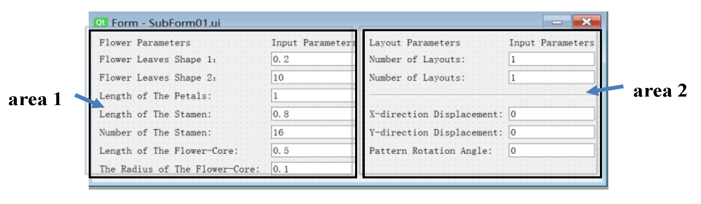
5.1. Setting Parameters to Generate Flower Patterns

In this experiment we used parameter settings to generate the basic elements that make up the flower and the entire flower pattern. Nonlinear functions based on Equation (6) and Equation (10) generated the basic elements of flower-leaves and petals. According to Equation (7) and Equation (11), the parameters a, b, and a1 affect the shapes of the flower-leaves, and petals. Among these, parameters a and b control the basic shape of the flower-leaves and parameter a1 controls the size of the basic shape of the petals. We fixed the size of the petals and set a1 = 1, that is, the length of the petals to 1. Figure 5 illustrates different basic shapes which were generated by setting the parameters as a = 0.2, b = 1.0, a = 0.2, b = 5.0, a = 0.2, b = 10.0, a = 0.2, b = 20.0, a = 0.1, b = 10.0, a = 0.2, b = 10.0, a = 0.3, b = 10.0, a = 0.4, and b = 10.0.
The nonlinear function based on Equation (14) generates the essential elements of pistils. According to Equation (15), the parameters r1 and m affect the shape of the pistil. Among these, parameter r1 controls the size of the basic shape of the pistil and parameter m controls the number of pistils, which are denoted by m.
The petal size and number of petals were fixed as a1 = 1, i.e., the petal’s length is 1, and n = 2, i.e., the number of petals is 8. Figure 6 illustrates the different basic shapes which were generated by setting parameters as r1 = 0.6a1, m = 16, r1 = 0.7a1, m = 16, r1 = 0.8a1, m = 16, r1 = 0.9a1, m = 16, r1 = 0.8a1, m = 8, r1 = 0.8a1, m = 8, r1 = 0.8a1, m = 16, r1 = 0.8a1, and m = 32.
The basic shape of the pistil is controlled by parameters r1 and m. Firstly, the value of parameter m was fixed to observe the influence of the change in parameter r1 on the pattern. It was found that when the parameter r1 = 0.8a1, the obtained pattern was closest to the original pattern. Secondly, the influence of the change in parameter m on the pattern was observed for r1 = 0.8a1. It was found that when parameter m = 16, the distribution of pistils was neither sparse nor dense, and the obtained pattern was closest to the original pattern. Next, we used the basic graphs with a = 0.2, b = 10, r1 = 0.8a1, and m = 16 to conduct subsequent experiments to generate flower patterns.
The basic elements of flower-cores were generated by a nonlinear function based on Equation (20). According to Equation (21), the parameters a2 and a3 affect the shape of the flower-core. Parameter a2 controls the size of the basic shape of the flower-core and parameter a3 controls the size of the round shape of the flower-core. Figure 7 indicates different basic shapes which were generated by setting parameters as a2 = 0.3a1, a2 = 0.4a1, a2 = 0.5a1, a2 = 0.6a1, a3 = 0.1a2, a3 = 0.2a2, a3 = 0.3a2, and a3 = 0.4a2.
Parameter a2 controls the basic shape of the flower-core. By observing Figure 7, we can see that the pattern obtained when a2 = 0.5a1 is closest to the original pattern. The parameter a3 controls the size of the central circle. By observing Figure 7, we can see that the ratio between the two patterns is the most harmonious when a3 = 0.2a2.
The parameters of the entire flower pattern have values of a = 0.2, b = 10.0, r1 = 0.8a1, m = 16, a2 = 0.5a1, and a3 = 0.2a2.

5.2. Setting Parameters to Generate Layout Patterns of Flowers

We then generated different layout patterns of flowers based on the above experimental results. According to a transformation function based on Equation (23), we were able to find that different pattern layouts are generated by changing the values of parameters P1 and P2, where P1 controls the number/density of flowers in the layout and P2 controls the shape of these flowers. Through the experiments it was found that the valid value range of parameter P1 was 2–6 and the valid value range of parameter P2 was 0.1–1P1.
Figure 8 shows the pattern layouts for P1 = 4, P2 = 1P1 and 0.618P1 and level = 1, 2, 3, and 4. In these pattern layouts a fractal was produced by Equation (21) in which the flower pattern had the basic shape parameters a = 0.2, b = 10.0, r1 = 0.8a1, m = 16, a2 = 0.5a1, and a3 = 0.2a2.
Figure 9 shows the pattern layouts for P1 = 4, P2 = 1, 0.618P1 and level = 1, 2, 3, and 4. In these pattern layouts we rotated the flower patterns of the above experiment by 45 degrees, after which a fractal was produced by Equation (23) in which the basic shape parameters of the flower pattern were a = 0.2, b = 10.0, r1 = 0.8 a1, m = 16, a2 = 0.5a1, and a3 = 0.2a2.
By observing Figure 8 and Figure 9 we can see that the value of parameter P1 represents the number of flowers and the layout characteristics. Parameter P1 = 2 gives two flowers and a symmetrical layout; parameter P1 = 3 gives three flowers and a three-circle layout; parameter P1 = 4 gives four flowers and a four-square layout; and parameter P1 = 5 gives five flowers and a five-circle layout. Further, the parameter P2 represents the shape change of each flower pattern.
Next we generated complete flower patterns based on basic flower patterns and constructed a basic batik flower frame based on a specific transformation of functions in where iterative calculations based on Equations (6), (10), (14), and (22) generated the flower patterns. Iterative calculations based on Equation (22) generated flower pattern layouts. Traditional batik flower patterns consist of a variety of decorative patterns, including geometric patterns. We were able to add some geometric patterns to our auto-generated flower patterns to produce beautiful batik patterns.
The essence of the L-system is that it is a rewrite system. Through the empirical generalization and abstraction of the plant object growth process, the state and description rules are initialized and a finite number of iterations are performed to generate a sequence of character which represents the topological construction of the plant. Geometric interpretation of the resulting string produces a very intricate fractal pattern.
Figure 10 shows the beautiful flower patterns which were generated with the geometric patterns added. By analyzing the layout characteristics of batik patterns it was able to be found that the layout characteristics are usually symmetrical or four-square. Therefore, in the final layout pattern, the four-square layout was used as an example. At this time level = 2 and the generation pattern can have both a four-square layout and a clear view of the internal structure of the flower. The application of an L-system automatically generates the geometric pattern in the figure. Each geometric pattern is a fractal pattern that is generated by iteration rules and is iterated using these rules.

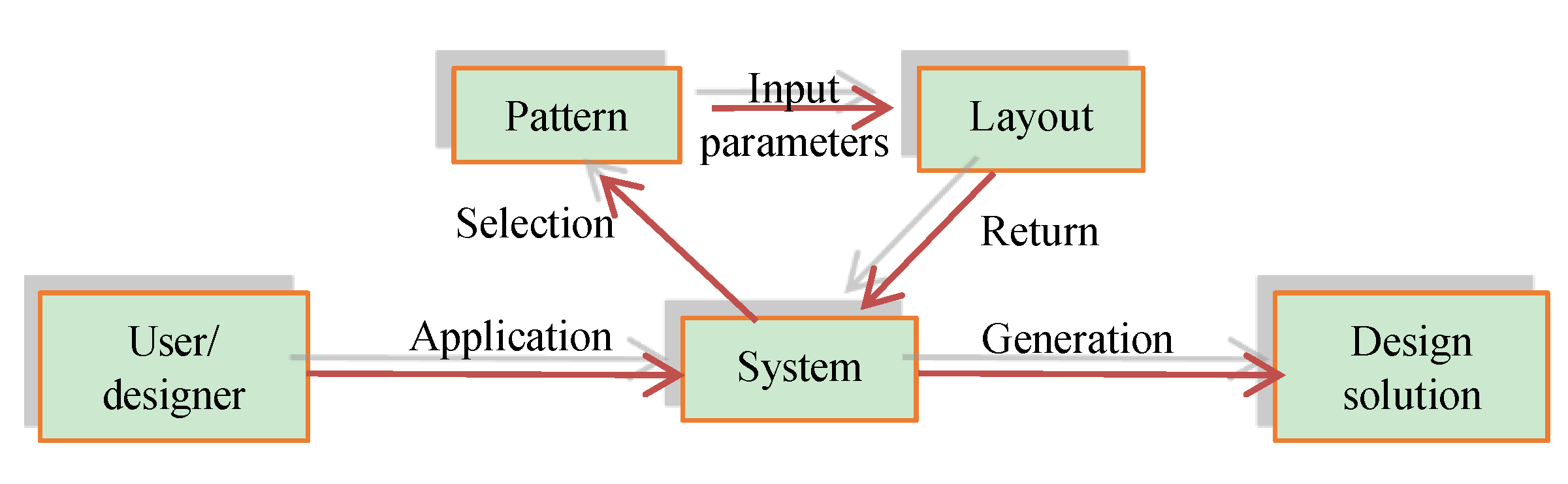
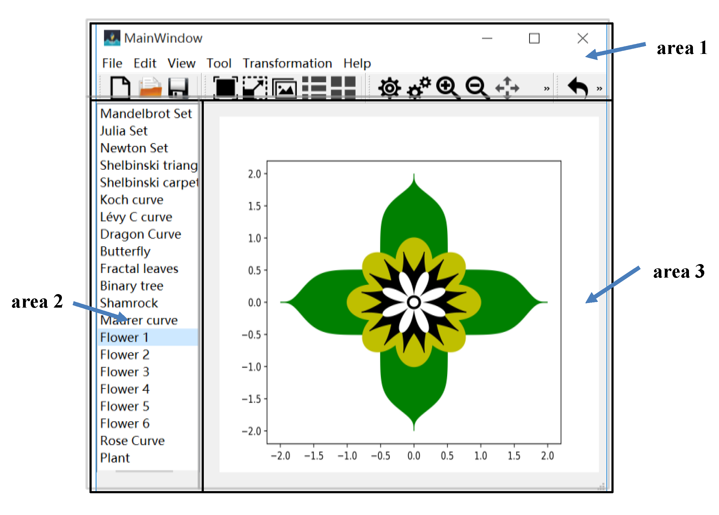
6. System Implementation
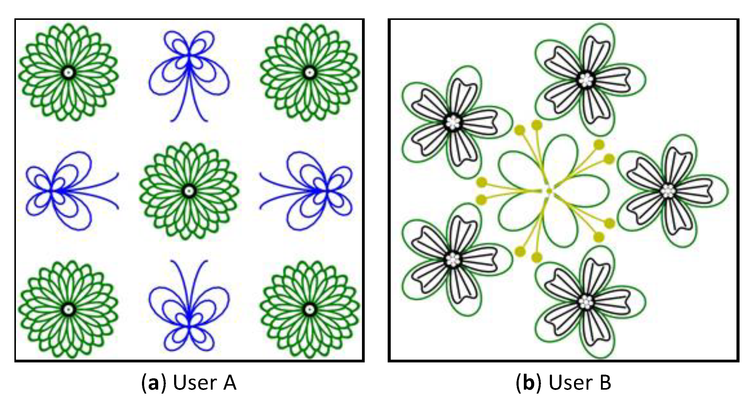
In order to verify the feasibility of the above method, an automatic batik pattern generation system was developed in the operating system Windows XP using Python and Qt. The system uses an interactive working method to parameterize the batik patterns and the user or designer automatically generates a series of different batik patterns by changing the parameter values of the batik pattern.
The digital batik pattern generation system is divided into three major modules: a system work module, a parameter setting module, and a pattern library module. In the process of generating a pattern, the batik pattern is parameterized and the initial value of the batik pattern parameter is assigned to generate an initial batik pattern which is stored in the pattern database. The user can use the initial pattern or modify the initialization parameters to generate the desired batik pattern, return the pattern, and display it in the system. The specific work implementation process of the system is shown in Figure 11.
The system work module is shown in Figure 12. Area 1 is a menu command area, which can perform the essential operations of the transformation of the pattern. Area 2 is a selection of the pattern area, and the pattern to be drawn can be selected from the pattern library. Area 3 is the pattern display area, which is used to display the initial pattern and the pattern which is constructed after modifying the parameters. In this system, the user or designer can select the batik pattern to be drawn in Area 2, while the selected initial batik pattern or modified pattern is displayed in Area 3.
The parameter setting module is shown in Figure 13. Area 1 contains the pattern variables, with the left side of the area being used to display the parameters of the pattern which can be changed and the right side being used to allow the input of the values of the parameters. Area 2 is the pattern layout area, the left side of which is used to display the parameters that control the pattern layout change and the right side to input the values of the parameters.
The user selects the pattern to be drawn in the system work module. At this time, the first pattern is generated in the drawing module and the parameter setting module is used to modify the parameters to generate different basic patterns. Taking the flower pattern as an example, several flower patterns may be generated by changing the value of the flower variable, different layout patterns may be generated by changing the values of the layout variables. The parameter value of the flower variable may be adjusted to generate the basic flower pattern. At this point in our experiments, the parameters for controlling the shape of the flower-leaves were set to 0.2 and 20, the parameter for controlling the length of the petal was set to 1, the parameter for controlling the length of the pistil was set to 0.8, and the parameter for controlling the number of petals was set to 16. The parameter to control the length of the flower-core was set to 0.5 and the parameter to control the radius of the flower circle was set to 0.1, with the resulting pattern shown in Figure 14a.
Next, on this basis, several flower layout patterns were generated by setting the values of the layout variables. The parameter value of the flower layout variable may be adjusted to generate a complete layout. At this point, the parameter for controlling the number of layouts was set to 4 and the parameter for controlling the number of iterations was set to 2. Moreover, the parameter for controlling the movement of the iteration pattern to move in the X-axis direction was set to 4/3, the parameter for controlling the movement of the iteration pattern in the Y-axis direction was set to 4/3. The resulting flower layout is shown in Figure 14b.
If the value of layouts and iterations are kept constant, the parameter for moving in the X-axis direction is set to 4/3, and the parameter for moving in the Y-axis direction is set to 0, the flower layout shown in Figure 14c is obtained.
Based on the introduction of rotational variables, the parameter for controlling the rotation of the base pattern was set to 45 and all the base patterns in layout map were rotated 45° clockwise, producing the pattern shown in Figure 14d.

7. Analysis

Through an automatic generation system based on fractal geometry, we were able to generate a large number of batik patterns with novel effects which retained the characteristics of original batik patterns. We have analyzed these batik patterns and extracted their basic features. “Elements number”, “Positional relationship”, and “Symmetry” have been extracted from the flower space structure. “Petals layers number”, “Petal shape”, “Petals number/layer”, and “Pistils number/petal” were extracted from the shape of the flower, as shown in Table 1. The “Elements number” refers to the essential element types that make up the flower and the “Positional relationship” refers to the relationship between the same elements.
Figure 15 shows the flower patterns generated by the system, the original batik pattern, and the original pattern binarization. Through comparing their basic features, it can be judged as to whether the generated patterns can effectively simulate traditional batik patterns. The primary features of the system-generated flower patterns the original flower patterns are shown in Table 2.
Comparing the original pattern features with general pattern features, it can be found that the generated flowers 1, 2, 3, and 5 are identical to the original pattern. The generated flower 4 is slightly different from the original pattern. Although there are two layers of petals, the number of petals in the second layer is different, and the number of stamens in the petals is also different. Flower 6 is also different from the original pattern. The flower layout of the original pattern is not a three-square layout in the strict sense, and the generated pattern is a rigid three-square layout; however, the characteristics of the single pattern in the layout map are relatively compatible. The user/designer can select the pattern to be drawn through the system interface and change the shape of the pattern by changing the initialization parameters. We invited design and non-design students to use the system in order to test whether our system can effectively simulate batik patterns during use.
User A was a design student who liked combining animal patterns and plant patterns to create a batik layout. Among these, the features of the flower were “2, rotation, 1/8, multi, curved, 10 or more, none”, and the butterfly layout was also a four-square layout. The user preferred a mirror-symmetric pattern with a four-square layout, as shown in Figure 16a.
User B was a non-design student who preferred to use plant patterns to create a batik layout. The layout of two different flowers generated a circle layout. The features of the two flowers are “2, rotation, 1/5, single, curved, 5, 2” and “multi, rotation, 1/5, double, curved and wavy, 5, none “. The user tended to use a point-symmetric with the circle layout, as shown in Figure 16b.

8. Conclusions

Based on the self-similarity, self-affine and scale-free fractal characteristics of traditional handmade batik flower patterns, this paper has proposed an automatic batik flower pattern generation method based on fractal geometry. Firstly, based on a two-dimensional iterated function system, an automatic flower pattern generation algorithm was proposed. A superellipse curve was introduced to achieve the generation of a flower-leaves pattern, a rose curve was introduced to achieve the generation of a petals pattern, a circular hypocycloid was introduced to achieve the generation of a pistil pattern, and a rose curve and a circular curve were introduced to achieve the generation of a flower-core pattern. Next a nonlinear function was defined, a generated flower pattern was introduced into the nonlinear function, and this function was iterated and changed to complete the pattern generation of different layouts. Finally, the variation law between the pattern shape and the parameter value was studied. Comparing the generated flower pattern features with the original flower pattern features, it could be found that most of the generated patterns’ features are consistent with the original pattern features. Although they differed when it came to some details, this did not affect the final result. A small part of the generated patterns differed in their features but the shape of the difference was still very similar to the original pattern, and no significant defects were produced. The batik patterns generated by the automatic generation system were therefore able to effectively simulate traditional batik patterns. Through experiments, the range of parameter values in each function were able to be obtained and the flower patterns of traditional hand-dyed batik were able to be effectively simulated to realize the automatic generation and digital design of the batik patterns. All the proposed methods were applied and tested and the results reached the expected goal.
Our future work will focus on extending the algorithm to other graphic designs, achieving full automatic simulation of batik patterns, enriching the diversity of batik patterns, and introducing color rendering based on patterns so that these patterns can adapt to the intelligent upgrade of China’s printing and dyeing industry.

Author Contributions

G.T. and Q.Y. proposed the generation algorithm of batik flower patterns and its layout; G.T., Q.Y., T.H., and Y.S. established the automatic generation system. Validation, T.H. and Y.S. All authors reviewed the manuscript.

Funding

This research was funded by the Guizhou Province Science and Technology Fund Project (Branch Support [2017]2870), the Guizhou Province Education Department Science and Technology Talents Support Project (Branch Support KY [2017]062), and the Guizhou Human Resources and Social Security Bureau (Hunan Project Fund [2016] 06).

Conflicts of Interest

The authors declare no conflict of interest.

References

  1. Wang, H.; Zhang, C.Y. Comparative study of ethnic groups’ batik patterns in Southwest China. J. Text. Res. 2016, 37, 101–106. [Google Scholar]
  2. Wang, T.F. Research on Miao Batik Art—Taking the Anshun Area of Guizhou as an Object. Master’s Thesis, Kunming University of Science and Technology, Kunming, China, November 2014. [Google Scholar]
  3. Zhang, X.H.; Li, H.Y. Production of art patterns based on fractal cloud model cellular automata. J. Tsinghua Univ. (Sci. Technol.) 2013, 53, 1098–1103. [Google Scholar]
  4. Cui, J.; Tang, M.X. Integrating shape grammars into a generative system for Zhuang ethnic embroidery design exploration. Comput. Aided Des. 2013, 45, 591–604. [Google Scholar] [CrossRef]
  5. Liu, S.G.; Chen, D. Computer simulation of batik printing patterns with cracks. Text. Res. J. 2015, 85, 1972–1984. [Google Scholar] [CrossRef]
  6. Falconer, K. Fractal Geometry: Mathematical Foundations and Applications; John Wiley & Sons Inc.: Hoboken, NJ, USA, 2004. [Google Scholar]
  7. Vicsek, T. Fractal Growth Phenomena; World Scientific Publishing Company: Singapore, 1992. [Google Scholar]
  8. Peters, E.E. Chaos and Order in the Capital Markets: A New View of Cycles, Prices, and Market Volatility; John Wiley & Sons Inc.: Hoboken, NJ, USA, 1996. [Google Scholar]
  9. Perrier, E.; Tarquis, A.M.; Dathe, A. A program for fractal and multifractal analysis of two-dimensional binary images: Computer algorithms versus mathematical theory. Geoderma 2006, 134, 284–294. [Google Scholar] [CrossRef] [Green Version]
  10. Ouahabi, A. Signal and Image Multiresolution Analysis; John Wiley & Sons Inc.: Hoboken, NJ, USA, 2012. [Google Scholar]
  11. Djeddi, M.; Ouahabi, A.; Batatia, H.; Basarab, A.; Kouamé, D. Discrete wavelet for multifractal texture classification: Application to medical ultrasound imaging. In Proceedings of the 17th IEEE International Conference on Image Processing, Hong Kong, China, 26–29 September 2010; pp. 637–640. [Google Scholar]
  12. Ouahabi, A. Multifractal analysis for texture characterization: A new approach based on DWT. In Proceedings of the 10th International Conference on Information Science, Signal Processing and their Applications, Kuala Lumpur, Malysia, 10–13 May 2010; pp. 698–703. [Google Scholar]
  13. Corbetta, D.; Spencer, J.P.; Thomas, M.; McClelland, J. Toward a Unified Theory of Development: Connectionism and Dynamic Systems Theory Re-Considered; Oxford University Press: Oxford, UK, 2009. [Google Scholar]
  14. Mandelbrot, B.B. A fractal set is one for which the fractal (Hausdorff-Besicovitch) dimension strictly exceeds the topological dimension. Fract. Chaos 2004, 978–1000. [Google Scholar]
  15. Pickover, C.A. Chaos and Fractals: A Computer Graphical Journey; Elsevier: Amsterdam, The Netherlands, 1998. [Google Scholar]
  16. Fisher, Y. Fractal Image Compression: Theory and Application; Springer Science & Business Media: Berlin, Germany, 2012. [Google Scholar]
  17. Jelinek, H.; Karperien, A.; Cornforth, D.; Cesar, R.M.J.; Leandro, J. MicroMod—An L-systems approach to neuron modelling. In Proceedings of the Sixth Australasia-Japan Joint Workshop on Intelligent and Evolutionary Systems, Canberra, Australia, 22–24 November 2002; pp. 156–163. [Google Scholar]
  18. Hahn, H.K.; Georg, M.; Peitgen, H.O. Fractal Aspects of Three-Dimensional Vascular Constructive Optimization. Fractals in Biology and Medicine; Birkhäuser Basel: Basel, Switzerland, 2005; pp. 55–66. [Google Scholar]
  19. Cannon, J.; Floyd, W.; Parry, W. Finite subdivision rules. Conform. Geom. Dynam. 2001, 5, 153–196. [Google Scholar] [CrossRef]
  20. Cannon, J.W.; Floyd, W.J.; Parry, W.R. Crystal Growth, Biological Cell Growth, and Geometry, Pattern Formation in Biology, Vision and Dynamics; Carbone, A., Gromov, M., Prusinkiewicz, P., Eds.; World Scientific Publishing Company: Singapore, 2000. [Google Scholar]
  21. Hariadi, Y.; Lukman, M.; Destiarmand, A.H. Batik fractal: Marriage of art and science. J. Vis. Art Des. 2013, 4, 84–93. [Google Scholar] [CrossRef]
  22. Indraprastha, A.; Sahputra, Z.; Suharjono, A. Preserving local ornament through algorithm. J. Ilmu Komput. Dan Inf. 2013, 6, 52–58. [Google Scholar]
  23. Riwansia, R.R. Pengembangan Desain Batik melalui Penggunaan Geometri Fraktal Koch Snowflake. Pros. Semin. Jember Univ. Jember 2016. [Google Scholar]
  24. Purnomo, K.D. Pembangkitan Segitiga Sierpinski dengan Transformasi Affine Berbasis Beberapa Benda Geometris. Prosiding Seminar Nasional Matematika. pp. 41–48. Available online: https://jurnal.unej.ac.id/index.php/psmp/article/view/977 (accessed on 19 December 2014).
  25. Romadiastri, Y. Batik Fraktal: Perkembangan Aplikasi Geometri Fraktal. Delta: J. Ilm. Pendidik. Matematika 2017, 1, 158–164. [Google Scholar]
  26. Muhamad, L.; Nancy, M.; Yun, H.P. Pixel People Project. Available online: http: //jbatik.com (accessed on 18 February 2019).
  27. Zhang, D.Y.; Chen, L.; Wang, H.J. Application of deterministic L-systems in knitting pattern design. J. Text. Res. 2015, 36, 35–38. [Google Scholar]
  28. Yuan, Q.N.; Lv, J.; Huang, H.S. Auto-Generation Method of Butterfly Pattern of Batik Based on Fractal Geometry. Int. J. Signal Process. Image Process. Pattern Recognit. 2016, 9, 369–392. [Google Scholar] [CrossRef]
  29. Zhang, X.W.; Wang, J.; Lu, G.D.; Fei, S.M.; Zhang, D.L. Extraction and reuse of pattern configuration based on ontology and shape grammar. J. ZheJiang Univ. (Eng. Sci.) 2018, 52, 461–472. [Google Scholar]
  30. Yuan, H.F.; Cheng, W.Y.; Wang, X.; Liu, X.H. Fractal pattern design based on Kronecker product and the application in Wangjiang cross stitch. J. Donghua Univ. (Nat. Sci.) 2017, 43, 651–654. [Google Scholar]
  31. Wang, S.H.; Yang, X.H. Generation of fractal image on complex plane and its application in textiles. J. Silk 2017, 54, 56–61. [Google Scholar]
  32. Lu, L.S.; Song, X.X. Application of fractal pattern in computer jacquard knitted fabric. J. Silk 2017, 54, 25–29. [Google Scholar]
  33. Falconer, K.J. Techniques in Fractal Geometry; Wiley: Hoboken, NJ, USA, 1997. [Google Scholar]
  34. Barnsley, M.F. Fractals Everywhere; Academic Press: New York, NY, USA, 2014. [Google Scholar]
  35. Dura, E.; Bell, J.; Lane, D. Superellipse Fitting for the Recovery and Classification of Mine-Like Shapes in Sidescan Sonar Images. IEEE J. Oceanic Eng. 2008, 33, 434–444. [Google Scholar] [CrossRef]
  36. Basieux, P. Abenteuer Mathematik: Brücken zwischen Wirklichkeit und Fiktion; Springer: Berlin, Germany, 2012. [Google Scholar]
  37. Wußing, H. 6000 Jahre Mathematik: Von den Anfängen bis Leibniz und Newton; Springer Spektrum: Berlin, Deutschland, 2013. [Google Scholar]
Figure 1. Traditional batik.
Applsci 09 02383 g001
Figure 2. Batik flower patterns.
Applsci 09 02383 g002
Figure 3. Flower-generation algorithm flow. Where parameters a and b control the basic shape of the flower-leaves; parameter a1 controls the size of the petals; parameter r1 controls the size of the pistil and parameter m controls the number of pistils; parameter a2 controls the size of the flower-core and parameter a3 controls the size of the round shape of the flower-core.
Applsci 09 02383 g003
Figure 4. Flower pattern generation process.
Applsci 09 02383 g004
Figure 5. Different basic flower patterns generated by setting parameters a and b.
Applsci 09 02383 g005
Figure 6. Different basic flower patterns generated by setting parameters a1 and m.
Applsci 09 02383 g006
Figure 7. Different flower patterns generated by setting parameters a2 and a3.
Applsci 09 02383 g007
Figure 8. Layout patterns generated by setting parameters P2 = 1P1 and 0.618P1 and level = 1, 2, 3, and 4.
Applsci 09 02383 g008
Figure 9. Layout patterns generated by setting parameters P2 = 1P1 and 0.618P1 and level = 1, 2, 3, and 4.
Applsci 09 02383 g009
Figure 10. The final flower pattern layouts.
Applsci 09 02383 g010
Figure 11. System implementation process.
Applsci 09 02383 g011
Figure 12. System work module.
Applsci 09 02383 g012
Figure 13. Parameter setting module.
Applsci 09 02383 g013
Figure 14. Basic flower pattern and flower layout patterns. (a) Basic flower pattern; (b) flower layout pattern with X-axis displacement of 4/3 and X-axis displacement of 4/3; (c) flower layout pattern with X-axis displacement of 4/3; (d) flower layout pattern with X-axis displacement of 4/3 and rotation of 45°.
Applsci 09 02383 g014
Figure 15. Batik flower patterns.
Applsci 09 02383 g015
Figure 16. User-generated patterns.
Applsci 09 02383 g016
Table 1. Basic features of flower patterns.
Basic FeaturesEvaluation Parameter
Elements number1, 2, 3, multi
Positional relationshipRotation, translation
SymmetryNone, 1/2, 1/3, 1/4, …, rotation
Petals layers numberSingle, double, multi
Petal shapeRhombus, curved, wavy
Petals number/layer6, 7, 8, 9, 10, or more
Pistils number/petalNone, 1, 2, multi
Table 2. Basic features of generated patterns and original patterns.
Flower PatternGenerationOriginal
Flower 12, rotation, 1/8, single, curved, 8, 12, rotation, 1/8, single, curved, 8, 1
Flower 23, rotation, 1/8, single, wavy, 8, 23, rotation, 1/8, single, wavy, 8, 2
Flower 32, rotation, 1/8, single, rhombus, 8, 22, rotation, 1/8, single, rhombus, 8, 2
Flower 42, rotation, 1/6, double, curved, 6, 2,2, rotation, 1/6, double, curved, 6 and 12, 4 and 5
Flower 52, rotation, 1/8, single, curved, 8, multi2, rotation, 1/8, single, curved, 8, multi
Flower 62, rotation, none, multi, curved,
10 or more, none
2, rotation, 1/3, multi, curved,
10 or more, none

